1
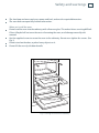
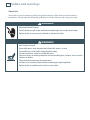
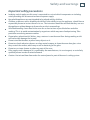
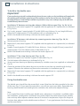
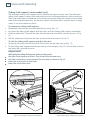
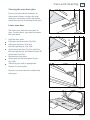
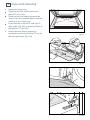
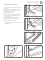
Built-in oven
OB60 double oven
under bench models
Installation instructions
and User guide
GB IE
Contents
Safety and warnings
Installation instructions
Using your oven for the first time
Clock and timer
Using the multifunction lower oven
Lower oven cooking functions
Automatic cooking
Using the upper oven for the first time
Upper oven cooking functions
Care and cleaning
Warranty and service
Important!
SAVE THESE INSTRUCTIONS
The models shown in this user guide may not be available in all markets and are
subject to change at any time. For current details about model and specification
availability in your country, please visit our local website listed on the back cover
or contact your local Fisher & Paykel dealer.
1
2
6
14
15
16
17
18
19
20
21
31
2
Safety and warnings
Installation
WARNING!
Electrical Shock Hazard
Always disconnect the oven from the mains electricity supply before
carrying out any maintenance operations or repairs.
Failure to do so may result in death or electrical shock.
WARNING!
Cut Hazard
Take care - panel edges are sharp.
Failure to use caution could result in injury or cuts.
Important safety precautions
To avoid hazard, follow these instructions carefully before installing or using this product.
Please make this information available to the person installing the product as it could reduce
your installation costs.
This oven is to be installed and connected to the electricity supply only by an authorised person.
If the installation requires alterations to the domestic electrical system call a qualified electrician.
The electrician should also check that the socket cable section is suitable for the electricity drawn
by the oven.
The oven must be earthed.
To connect the oven to the mains, do not use adapters, reducers or branching devices as they can
cause overheating and burning.
Installation must comply with your local building and electricity regulations.
Failure to install the oven correctly could invalidate any warranty or liability claims.
Before you install the oven, please make sure that
The cabinetry surrounding the oven is made of heat resistant material. It must be capable of
resisting temperatures of 75 oC above room temperature.
The adhesive which bonds the plastic laminate to the cavity can withstand at least 150 oC. This is
to avoid delamination.
A suitable disconnection switch is incorporated in the permanent wiring, mounted and positioned
to comply with the local wiring rules and regulations. The switch must be of an approved
type installed in the fixed wiring and provide a 3 mm air gap contact separation in all poles in
accordance with the local wiring rules.
The electrician allows at least 1.5 m (and not more than 2 m) free length of connection cable
within the cavity for ease of installation and servicing of the product. The mains cable should not
touch any hot metal parts.
Safety and warnings
3
The benchtop and oven cavity are square and level, and are the required dimensions.
The oven door can open fully without obstruction.
When you install the oven
Do not seal the oven into the cabinetry with silicone or glue. This makes future servicing difficult.
Fisher & Paykel will not cover the costs of removing the oven, or of damage caused by this
removal.
Use the supplied screws to secure the oven to the cabinetry. Do not over-tighten the screws. (See
Fig. 1)
Do not stand on the door, or place heavy objects on it.
Do not lift the oven by the door handle.
Fig. 1 Securing the oven to the cabinetry
4
Safety and warnings
Operation
Your built-in oven has been carefully designed to operate safely during normal cooking
procedures. Please keep the following guidelines in mind when you are using your oven:
WARNING!
Electrical Shock Hazard
Switch the oven off at the wall before replacing fuses or the oven lamp.
Failure to do so may result in death or electrical shock.
WARNING!
Hot Surface Hazard
Accessible parts may become hot when this oven is in use.
To avoid burns and scalds keep children away.
Do not touch hot surfaces inside the oven.
Use oven mitts or other protection when handling hot surfaces such as oven
shelves or dishes.
Take care when opening the oven door.
Let hot air or steam escape before removing or replacing food.
Failure to do so could result in burns and scalds.
Safety and warnings
5
Important safety precautions
Isolating switch: make sure this oven is connected to a circuit which incorporates an isolating
switch providing full disconnection from the power supply.
Household appliances are not intended to be played with by children.
Children, or persons with a disability which limits their ability to use the appliance, should have a
responsible person to instruct them in its use. The instructor should be satisfied that they can use
the appliance without danger to themselves or their surroundings.
Safe food handling: leave food in the oven for as short a time as possible before and after
cooking. This is to avoid contamination by organisms which may cause food poisoning. Take
particular care during warmer weather.
Do not place aluminium foil, dishes, trays, water or ice on the oven floor during cooking as this
will irreversibly damage the enamel.
Do not stand on the door, or place heavy objects on it.
Do not use harsh abrasive cleaners or sharp metal scrapers to clean the oven door glass since
they scratch the surface, which may result in shattering of the glass.
Do not use a steam cleaner to clean any part of the oven.
If the supply cord is damaged, it is replaced by the manufacturer, its service agent, or a similarly
qualified person in order to avoid a hazard.
Caution. Hot air can blow from under the control panel as part of the oven's cooling system.
6
Installation instructions
To build in the double oven
Important!
If you are planning to install a cooktop directly above the oven, make sure the installation will comply with
the cabinetry and ventilation requirements of the cooktop as well as those of the oven. Bench heights,
benchtop thicknesses and cooktop installation requirements vary: some cooktops may not be able to be
installed directly above the oven.
Installation “A” between existing side cabinets (560 or 600 mm gap) (Figs. 2a, 2b, 3a, 3c)
Mount the 2 (two) metal supports “B” (supplied with the appliance in a separate kit) as indicated
in Fig. 2b, 3c).
Fig. 3c only, prepare 2 wood uprights “A” (width 20-50 mm, thickness 18 mm, length 650 mm);
mount the 2 wood uprights “A” to the cabinet walls as indicated in Fig. 3c.
Build in the double oven making it slide on the metal supports “B”.
Installation “B” between side cabinets by removing previous housing (Figs. 3b, 3c)
Remove previous housing.
Mount the 2 (two) metal supports “B” (supplied with the appliance in a separate kit) as indicated
in Fig. 3c).
Prepare 2 wood uprights “A” (width 20-50 mm, thickness 18 mm, length 650 mm); mount the 2
wood uprights “A” to the cabinet walls as indicated in Fig. 3c.
Build in the double oven making it slide on the metal supports “B”.
Installation “C” by using housing unit (Figs. 4a, 4b)
Remove the upper cross member support as indicated in Fig. 4a.
Cut the bottom of the housing as indicated in Fig. 4a.
Screw oven base housing to adjoining cabinetry by suitable screws (not supplied) as indicated in
Fig. 4b.
Check the position of the cabinet legs to ensure the cut-out does not interfere with the legs’
support. Otherwise the cabinet may have to be removed as in installation type "B".
Mount the 2 (two) metal supports “B” (supplied with the appliance in a separate kit) as indicated
in Figs. 4b).
Build in the double oven making it slide on the metal supports “B”.
Fixing the double oven
The double oven should then be secured by 6 screws fitted into the holes provided at the sides
of the oven (Fig. 5). If you open the oven doors, you will see some screw holes. Remember the
housing should not be free standing but be secured to the wall and/or adjacent fittings.
Note:
It is essential that when installing your double oven, adequate air circulation is available within
the installation. Inadequate air circulation may greatly impair the performance of your double
oven and may affect adjacent cabinets due to an increase in temperature. Adjust the hinges of
furniture door adjacent to the double oven to allow a 5 - 7 mm gap between the furniture door
and the oven frame.
Installation instructions
INSTALLATION “A”
Fig. 2a
(*)Measure calculated from the
underneath of the benchtop to the top
support base of the “B” supports.
570
min
Important!
720 min (*)
WARNING
The
underside!of the cabinet
VERY
shall
be IMPORTANT
opened to allow
The underside of the
correct
air
circulation.
cabinet shall
be
opened to allow
correct air circulation.
538
718
B
560
4
54
59
5
20
42
B
Support
base
Support base
Fig. 2b
7
8
Installation instructions
INSTALLATION
“B”
INSTALLATION “B”
Pre existing
600 mm cabinetry
Fig. 3a
Fig. 3b
(*)Measure calculated from the underneath
570
(*of
)Measure
calculated
the underneath
of
the worktop
to the from
top support
base of the
the worktop to the top support base of the
“B”
“B”supports.
supports.
min
Important!
WARNING !
The
underside
of the cabinet
VERY
IMPORTANT
shall
be
opened
to allow
The underside
of the
correct
air circulation.
cabinet
shall be
opened to allow
correct air circulation.
720 min (*)
650
A
538
718
B
600
20
0
-5
18
A
4
5
20
15
54
59
22
20
Fig. 3c
B
Support base
Support
base
Installation instructions
(*)Measure calculated from the underneath
of the benchtop to the top support base of
the “B” supports.
INSTALLATION “C”
720 min (*)
600
30
Cabinet for
installing the
oven
Remove single
oven shelf,
if fitted.
B
40
Fig. 4a
40
Support
Support
base
base
30
15
36
15
18
18
42
B
25
30
538
718
B
4
Fig. 6.1b
54
59
5
20
Fig. 4b
9
Installation instructions
10
10
200
Fitting the 6 fixing screws to the kitchen
base unit.
Important!
If installing a base panel leave a space as
indicated in Fig. 5 to allow air circulation.
2 mm
Fig. 5
10 mm
Important!
Hot air can blow from under the control panel as
part of the oven's cooling system.
Air circulation
11
OVEN DOOR
LOWER TRIM
AIR FLOW
Fig. 6 Correct and incorrect placement of trim
Important!
Please take extra care not to damage the lower trim of the oven.
The space between the bottom of the door and the lower trim is important for the correct air
circulation into the oven.
Ensure the oven sits on wooden blocks or similar supports when it is removed from the carton as
shown in Fig. 6. This will prevent any damage to the lower trim.
After installation check the lower trim is still undamaged. Open the oven door slowly to its fully
open position ensuring there is adequate clearance between the bottom of the door and the
lower trim.
Should the lower trim become damaged, straighten the trim and ensure the oven door opens
fully without obstruction from the lower trim.
Note: ensure that the oven does not sit on the lower trim.
The manufacturer does not accept responsibility for any damage to the oven resulting from
incorrect installation.
12
Connecting the power supply cable
Feeder cable section type H05RR-F or H05VV-F
230- 240 V
3 x 2.5 mm2
4060-4400 W
Unscrew the screws “A” securing the cover plate “B” behind the oven (Fig. 7).
Remove the cover plate “B”.
Remove the screws “C” from the cable clamp (Fig. 8).
Insert the mains cable (type H05RR-F or H05VV-F) into the cable protector “P”.
Connect the phase and earth cables to the mains terminal connection block “D”.
The wires of this appliance must be coloured in accordance with the following code:
GREEN AND YELLOW - EARTH
BLUE - NEUTRAL “N”
BROWN - LIVE “L”
The wire which is coloured GREEN AND YELLOW must be connected to the terminal which is
marked with the letter “E” or by the Earth
symbol or coloured GREEN or GREEN AND YELLOW.
The wire which is coloured BLUE must be connected to the terminal which is marked with the
letter “N” or coloured BLACK.
The wire which is coloured BROWN must be connected to the terminal which is marked with the
letter “L” or coloured RED.
Refit the cable clamp so that it clamps the outer sleeving of the cable, and screw the screws “C”.
Refit the cover plate “B” and fix it with the screws “A”.
DD
AA
BB
Brown
Brown(Live)
(Live)
Blue
Blue(Neutral)
(Neutral)
Green &
Yellow
&
(Earth)
Yellow
(Earth)
P
P
C
C
Important:
This appliance must be earthed.
Fig. 7
Fig. 8
13
14
Using your oven for the first time
8
1
2
3
4
5
6
7
8
7
1
2
Control panel
Control buttons (for main oven only)
Upper oven function knob
Upper oven temperature knob
Main (lower) oven function knob
Main (lower) oven temperature knob
Main (lower) oven temperature indicator light
Upper oven temperature indicator light
Clock display
6
4
3
5
Fig. 9 Control panel
Using the multifunction lower oven for the first time
1
2
3
4
Before using your new oven, please:
Read this user guide, taking special note of the ‘Safety and warnings’ section.
Remove all accessories and packaging.
Set the clock. The oven will not work until the clock has been set.
Condition the oven:
Put in the shelves and trays. If you are not using
the sliding shelf supports, then slide in the shelves
and grill pan as shown in Fig. 10. Fit them between
the metal runners, with the safety stop notch down
and at the back. (If the shelf supports and catalytic
panels are not already fitted, see ‘Care and cleaning’
for how to do this).
Heat the oven on maximum for:
60 minutes in the
position
15 minutes in the
position
Fig. 10 Correct position of shelves and pan
5
Wipe out the oven with a damp cloth and mild detergent,
and dry thoroughly.
Note: the oven cooling fan comes on automatically at different stages of the cooking cycle. It
blows out warm air above the door. When the oven is turned off, the cooling fan may stay on
until the oven cools down.
Clock and timer
15
Buttons:
Timer
Cooking time
End of cooking time
Decreases the number shown on the display or
changes the volume of the beeps
Increases the number shown on the display
Fig. 11 Clock display and control buttons
Illuminated symbols:
A
A
- flashing - oven in automatic position but not set
- steady illumination - oven set for automatic cooking
Cooking taking place
Timer in operation
Setting the clock
When first connected, or after a power failure, ‘0.00’ will flash on the display.
To set the clock, press the
and
buttons together and then the
and
Note: changing the time will delete any automatic program.
Using the timer
The timer can be set for up to 23 hours and 59 minutes.
To set the timer, press the
button, then the
and
buttons.
To check the remaining time press the
button.
When the time is up, the timer will beep. Put ‘Press the
button to turn it off.
Note: if ‘A’ is flashing on the display, press the
and
buttons together.
Setting the timer volume
You can select from three volume levels by pressing the
button.
buttons.
16
Using the multifunction lower oven
Fig. 12 Function knob
1
2
3
Fig. 13 Temperature knob
Select the function using the function control knob. The oven lights will come on.
Select the temperature using the temperature control knob. The oven temperature indicator
light, above the temperature knob on the control panel, will glow until the oven has reached the
set temperature, and then it will go out.
When you have finished cooking, turn the function and temperature control knobs to the off O
position.
Note: if ‘A’ is flashing or steadily illuminated on the display, press the
together.
and
buttons
Lower oven cooking functions
17
OVEN LAMP
Only the oven light comes on. It remains on in all the cooking functions.
DEFROST
Only the oven fan comes on. Use with the temperature knob set to O. The fan circulates air
around the oven, speeding up the defrosting process by approximately 30%.
Note: this function is not for cooking food.
FAN FORCED
The circular heating element and the fan come on. The oven set on FAN FORCED can cook
several different foods together. Use FAN FORCED for multi-shelf cooking.
GRILL
The grill at the top of the oven comes on. Preheat for five minutes. Use with the oven door
closed and the temperature knob between 50 °C and 225 °C max. Do not grill for longer than 30
minutes at any one time. For best results, use the topmost shelf position when you want quick
browning (eg toast).
Important!
Safe food handling: leave food in the oven for as short a time as possible before and after cooking or
defrosting. This is to avoid contamination by organisms which may cause food poisoning. Take particular
care during warmer weather.
Notes on baking and roasting:
Only use the fat filter for roasting. Remove before baking. Always clean the filter after
cooking.
Preheat the oven before baking.
Do not place anything, including water
or ice, on the oven floor.
Fig. 14 Fat filter
18
Automatic cooking
Use automatic cooking to automatically turn the lower oven on, cook, and then turn the lower
oven off.
1
2
3
4
5
Check the clock shows the correct time.
Select the function and temperature. The oven will come on.
Decide how long the food will take to cook, allowing time for preheating if necessary.
Press the
button. 0.00 will show. Using the
buttons, set the cooking time.
Select the time you would like the oven to turn off by pressing the
button, and then using
the
buttons.
If there is time to wait before cooking starts, the current time of day and A will show in the clock
display. The oven temperature and function lights will go out and the oven will switch off but is
now set for automatic cooking. Note: the cooling fan may remain on.
If you are already at home to turn the oven on and only want the oven to turn off automatically,
start cooking as normal, then follow step 4 or step 5 to set a time to stop the oven.
When automatic cooking starts,
will be displayed and the oven will turn on.
To see the remaining cook time, press the
button.
To see the set stop time, press the
button.
To cancel automatic cooking at any time, press the
and
and function knobs to the off O position.
button and turn the temperature
When the stop time is reached, the oven will turn off, the timer will beep and A will flash:
To stop the beeping and return the oven to manual mode, press the
and
buttons
together.
Turn the temperature and function knobs to the off O position.
Important!
Safe food handling: leave food in the oven for as short a time as possible before and after
cooking. This is to avoid contamination by organisms which may cause food poisoning. Take
particular care during warmer weather.
Using the upper oven for the first time
19
Upper oven
1
2
3
4
Before using your new oven, please:
Read this user guide, taking special note of the ‘Safety and warnings’ section.
Remove all accessories and packaging.
Condition the oven:
Put in the shelves and trays. If you are not using
the sliding shelf supports, then slide in the shelves
and grill pan as shown in Fig. 15. Fit them between
the metal runners, with the safety stop notch down
and at the back. (If the shelf supports and catalytic
panels are not already fitted, see ‘Care and cleaning’
for how to do this).
Heat the oven on maximum for:
60 minutes in the
position
15 minutes in the
position
Wipe out the oven with a damp cloth and mild detergent,
and dry thoroughly.
Note: the oven cooling fan comes on automatically
at different stages of the cooking cycle. It blows out
warm air above the door. When the oven is turned off,
the cooling fan may stay on until the oven cools down.
Fig. 15 Correct position of shelves and pan
20
Upper oven cooking functions
Fig. 16 Upper oven function and temperature knobs
OVEN LAMP
Only the oven light comes on. It remains on in all the cooking functions.
BAKE
The upper and lower heating elements come on. BAKE is the traditional method of cooking. It is
best to cook on only one shelf at a time in this function.
GRILL
The grill at the top of the oven comes on. Preheat for five minutes. Use with the oven door
closed and the temperature knob between 50 °C and 225 °C max. Do not grill for longer than 30
minutes at any one time. For best results, use the topmost shelf position when you want quick
browning (eg toast).
Notes on baking:
Preheat the oven before baking.
Do not place anything, including water or ice, on the oven floor.
Care and cleaning
21
Important!
Before you start cleaning your oven, please:
Read these cleaning instructions and the ‘Safety and warnings’ section at the start of this user
guide.
Turn the oven off at the wall.
Make sure the oven is a safe temperature to touch.
Do not use a steam cleaner.
Do not keep flammable substances in the oven.
General advice
Wipe out the oven after every use.
Wipe up spills. Avoid leaving alkaline or acidic substances (such as lemon juice or vinegar) on
the oven surfaces.
Do not use cleaning products with a chlorine or acidic base.
Cleaning the outside of the oven
Important!
Do not use abrasive cleaners, cloths or pads on the outside surfaces of the oven.
Immediately wipe off any caustic cleaners if they are spilled onto the oven door handle.
Wipe the oven’s outside surfaces often, using warm water and a mild household detergent. The
stainless steel may also be cleaned with a suitable cleaner and polish.
Note: if you choose to use a commercial stainless steel cleaner, please read the label to make
sure it does not contain chlorine compounds as these are corrosive and may damage the
appearance of your oven.
22
Care and cleaning
Cleaning the inside of your ovens
Do not use abrasive cleaners, cloths or pads to clean the enamel.
Do not use any oven cleaners, abrasive cleaners, ammonia-based cleaners, products containing
acids or alkalis, or detergents on the catalytic panels (not supplied with all models).
Fig.17 Removing the lower oven side racks and
catalytic panels (some models only)
To make cleaning easier, you can remove the side racks, the oven door, and the fat filter. The grill
element is self-cleaning.
Cleaning the upper oven
Do not use abrasive cleaners, cloths or pads to clean the enamel.
To make cleaning easier, you can remove the side racks.
Fig.18
Fig.19 Removing the upper oven side racks
Care and cleaning
23
Cleaning the enamel cavity
Clean the enamel on the inside of the oven when it has cooled down, using household
detergents or an ammonia-based cleaner. You may use ‘off the shelf’ oven cleaners, if you
carefully follow the manufacturers’ instructions.
Caring for the catalytic panels (some models only)
The catalytic panels are covered with a special microporous enamel which absorbs and does
away with oil and fat splashes during normal cooking over 200 °C. If, after cooking very fatty
foods, the panels remain dirty, heat the oven on maximum for an hour to an hour and a half,
and they will self-clean. The side panels are reversible. Make sure that you replace them with the
arrow up, and on the correct side. To remove the side catalytic panels you first need to unscrew
the side racks. See Fig. 17.
When you replace the panels, make sure that the arrows are pointing upwards.
Then screw the side racks back onto the oven wall. Ensure they are the right way up (Fig. 17).
Note: in some models, the back panel of the oven is also a catalytic liner, but this is not
reversible and should not be removed.
Cleaning the fat filter (lower oven)
Clean the fat filter after every use. If the filter is not cleaned, it will block and shorten the life of
the fan element. If it is lightly soiled, place the filter in a dishwasher on normal wash. If the filter
is very dirty, place in a saucepan with either two tablespoons of clothes washing powder, or one
tablespoon of dishwashing powder. Bring to the boil and leave to soak for at least 30 minutes.
Rinse the filter in clean water and dry.
Fig.20 Fat filter
24
Care and cleaning
Sliding shelf supports (some models only)
The telescopic sliding shelf supports can be fitted in the upper or lower oven. The telescopic
sliding shelf supports make it safer and easier to insert and remove the oven shelves and trays.
They stop when they are pulled out to the maximum position. Wipe the supports with a damp
cloth and a mild detergent only. Do not wash them in the dishwasher, immerse them in soapy
water, or use oven cleaner on them.
1
2
3
4
1
2
To remove the sliding shelf supports:
Remove the side racks by unscrewing the fixing screws (Fig. 17).
Lay down the sliding shelf support and side racks, with the sliding shelf support underneath.
Find the safety locks. These are the tabs that clip over the wire of the side rack (arrow 1 in Fig.
21).
Pull the safety locks away from the wire to release the wire (arrow 2 in Fig. 21).
To refit the sliding shelf support onto the side racks:
Screw the side racks onto the oven wall. Ensure they are the right way up (Fig. 17).
Fit the sliding shelf support onto the top wire of a rack and press (Fig. 22). You will hear a click as
the safety locks clip over the wire.
Important!
When fitting the sliding shelf supports, make sure that you fit:
the slides to the top wire of a rack. They do not fit on the lower wire.
the slides so that they run out towards the oven door, as shown in Fig. 22.
both sides of each pair of shelf slides.
both sides on the same level.
1
2
1
Fig.21 Removing the sliding shelf supports
Fig.22 Refitting the sliding shelf supports
Care and cleaning
25
Cleaning the oven door glass
Do not use harsh abrasive cleaners or
sharp metal scrapers to clean the oven
door glass since they scratch the surface,
which may result in shattering of the glass.
Lower oven door
The lower oven door has two panes of
glass. To clean these, you need to remove
the inner pane.
1
2
Lock the door open:
Fully open the oven door (Fig. 23b).
Fully open the lever “A” on the
left and right hinges, (Fig. 23b).
Gently close the door (Fig. 23c) until the
left and right hinges are hooked to part “B”
of the door (Fig. 23b).
Fig.23a
A
B
Remove the inner pane:
Gently pull out the inner pane of glass
(Fig. 23d).
Clean the glass with an appropriate
cleaner. Dry thoroughly.
Fig.23b
Fig.27
Now you can also clean the inside of the
outer glass.
Fig.23c
Fig.23d
26
3
4
Care and cleaning
Replace the inner pane:
Check that the four rubber pads are in
place (“D” in Fig. 24a).
Check that you are holding the pane the
correct way. You should be able to read the
wording on it as it faces you.
Insert the pane in the left “E” and right “F”
slide guides (Fig. 24b), and gently slide it to
the retainers “H” (Fig. 24c).
D
Unlock the oven door by opening it
completely and closing the lever “A” on the
left and right hinges (Fig. 24d).
Fig.24a
E
F
Fig.24b
H
Fig.24c
A
Fig.24d
Care and cleaning
27
Upper oven door
The upper oven door has two panes of
glass. To clean these, you need to remove
the inner pane.
1
2
Lock the door open:
Fully open the oven door (Fig. 25b).
Fully open the lever “A” on the
left and right hinges, (Fig. 25b).
Gently close the door (Fig. 25c) until the
left and right hinges are hooked to part “B”
of the door (Fig. 25b).
Remove the inner pane:
Remove the seal “G” by unhooking the two
fixing hooks (Fig. 25d).
Gently pull out the inner pane of glass
(Fig. 25e).
Clean the glass with an appropriate
cleaner. Dry thoroughly.
Fig.25a
A
B
Fig.25b
Now you can also clean the inside of the
outer glass.
Fig.25c
G
Fig.25e
Fig.25d
28
3
4
Care and cleaning
Replace the inner pane:
Check that the four rubber pads are in
place (“D” in Fig. 26a).
Check that you are holding the pane the
correct way. You should be able to read the
wording on it as it faces you.
Insert the pane in the left “E” and right “F”
slide guides (Fig. 26b), and gently slide it to
the retainers “H” (Fig. 26c).
Replace the seal “G” by hooking in the two
fixing hooks. Make sure that you put it in
the correct way. (Fig. 26d).
Note: the gap between the top edge of
the inner glass and the sealed gasket is to
allow air circulation (Fig. 26f ).
D
Fig.26a
E
F
Unlock the oven door by opening it
completely and closing the lever “A” on the
left and right hinges.
Fig.26b
H
Fig.26c
Fig.26f
G
A
Fig.26e
Fig.26d
Care and cleaning
29
Removing the oven door(s)
The oven door(s) can easily be removed as
follows:
Open the door to its full extent (Fig. 27a).
Open the lever “A” completely on the left
and right hinges (Fig. 27b).
Hold the door (Fig.27c).
Gently close the door until left and right
hinge levers “A” are hooked to part “B” of
the door (Fig. 27d).
Withdraw the hinge hooks from their
location following arrow “C” (Fig. 27e).
Rest the door on a soft surface.
Fig.27a
A
To replace the door, repeat the above steps
in reverse order.
B
Fig.27b
Fig.27c
C
Fig.27e
Fig.27d
30
Care and cleaning
Replacing the oven lamp
Let the oven cavity and the heating elements cool down.
Remove the protective cover “B”.
Unscrew and replace the bulb “A” with a new one suitable for high temperatures (300°C) with the
specifications: 230-240V 50 Hz, 15W, E14
Refit the protective cover.
Note: oven bulb replacement is not covered by your warranty.
A
B
Fig.28 Removing the oven lamp
Warranty and service
31
Before you call for service or assistance ...
Check the things you can do yourself. Refer to the installation instructions and your user guide
and check that:
1
2
Your product is correctly installed.
You are familiar with its normal operation.
If after checking these points you still need assistance, please refer to the Service & Warranty
book for warranty details and your nearest Authorised Service Centre, or contact us through our
local website listed on the back cover.
This oven has been designed and constructed in accordance with the following
codes and specifications:
In New Zealand and Australia:
AS/NZS 60335-1 General Requirements for Domestic electrical appliances
AS/NZS 60335-2-6 Particular Requirements for Domestic electrical cooking appliances
AS/NZS 1044 Electromagnetic Compatibility Requirements.
In Europe:
Safety requirements of EEC Directive “Low voltage” 2006/95:
- EN 60335-1 General Requirements for Domestic electrical appliances
- EN 60335-2-6 Particular Requirements for Domestic electrical cooking appliances
Safety requirements of EEC Directive “EMC” 89/336:
- EN 55014-1, EN 55014-2, EN 61000-3-2, EN 61000-3-3 Electromagnetic Compatibility
Requirements
Requirements of EEC Directive 93/68.
European directive 2002/96/EC on Waste Electrical and Electronic Equipment (WEEE)
(for European Union countries only)
GB This appliance is marked according to the European directive 2002/96/EC on Waste Electrical
and Electronic Equipment (WEEE). By ensuring this product is disposed of correctly, you will help
prevent potential negative consequences for the environment and human health, which could
otherwise be caused by inappropriate waste handling of this product.
The symbol
on the product, or on the documents accompanying the product, indicates that
this appliance may not be treated as household waste. Instead it shall be handed over to the
applicable collection point for the recycling of electrical and electronic equipment. Disposal
must be carried out in accordance with local environmental regulations for waste disposal.
For more detailed information about treatment, recovery and recycling of this product, please
contact your local city office, your household waste disposal service or the shop where you
purchased the product.
www.fisherpaykel.co.uk
www.fisherpaykel.ie
Copyright © Fisher & Paykel 2010. All rights reserved.
The product specifications in this booklet apply to the specific products
and models described at the date of issue. Under our policy of continuous
product improvement, these specifications may change at any time. You
should therefore check with your Dealer to ensure this booklet correctly
describes the product currently available.
GB IE
F&P PN - 599381 C
F&P ITALY PN - 1102984-ß3
07.2010