1
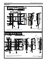
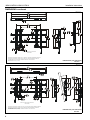
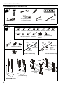
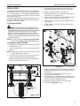
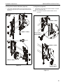
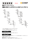
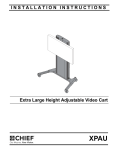
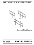
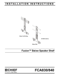
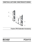
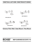
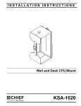
INSTALLATION INSTRUCTIONS
MTM1U
MSM1U
LSM1U
LTM1U
FUSION HEIGHT ADJUST
FLAT PANEL MOUNTS
MSM1U/MTM1U/LSM1U/LTM1U
MSM1U/MTM1U/LSM1U/LTM1U
Installation Instructions
DISCLAIMER
Milestone AV Technologies, and its affiliated corporations and
subsidiaries (collectively "Milestone"), intend to make this
manual accurate and complete. However, Milestone makes no
claim that the information contained herein covers all details,
conditions or variations, nor does it provide for every possible
contingency in connection with the installation or use of this
product. The information contained in this document is subject
to change without notice or obligation of any kind. Milestone
makes no representation of warranty, expressed or implied,
regarding the information contained herein. Milestone assumes
no responsibility for accuracy, completeness or sufficiency of
the information contained in this document.
Chief® is a registered trademark of Milestone AV Technologies.
All rights reserved.
WARNING: Never operate this mounting system if it is
damaged. Return the mounting system to a service center for
examination and repair.
WARNING: Do not use this product outdoors.
IMPORTANT ! : The MSM1U/MTM1U/LSM1U/LTM1U mounts
are designed to be mounted to:
•
•
a bare 8" concrete or 8"x8"x16" concrete block wall, or
a 2" x 4" wood studs wall covered by drywall with
maximum thickness of 5/8":
•
MSM1U/MTM1U: Wood studs must be 16" on
center;
•
LSM1U/LTM1U: Wood studs may be 16" or 24" on
center.
--SAVE THESE INSTRUCTIONS-IMPORTANT SAFETY INSTRUCTIONS
WARNING: A WARNING alerts you to the possibility of
serious injury or death if you do not follow the instructions.
CAUTION: A CAUTION alerts you to the possibility of
damage or destruction of equipment if you do not follow the
corresponding instructions.
WARNING: Failure to read, thoroughly understand, and
follow all instructions can result in serious personal injury,
damage to equipment, or voiding of factory warranty! It is the
installer’s responsibility to make sure all components are
properly assembled and installed using the instructions
provided.
WARNING: Failure to provide adequate structural strength
for this component can result in serious personal injury or
damage to equipment! It is the installer’s responsibility to
make sure the structure to which this component is attached
can support five times the combined weight of all equipment.
Reinforce the structure as required before installing the
component.
WARNING: Exceeding the weight capacity can result in
serious personal injury or damage to equipment! It is the
installer’s responsibility to make sure the combined weight of
all components located on the MSM1U/MTM1U does not
exceed 125 lbs (56.7 kg); OR 200 lbs (90.7 kg) for the LSM1U/
LTM1U.
WARNING: Use this mounting system only for its intended
use as described in these instructions. Do not use
attachments not recommended by the manufacturer.
2
Installation Instructions
MSM1U/MTM1U/LSM1U/LTM1U
DIMENSIONS
MSM1U
6.00
152.4
1.
2.
3.
RAILS CAN BE SLID LEFT OR RIGHT
FOR OFFSET
MAXIMUM MOUNTING PATTERN IS 22.7" (576 mm) WITHOUT REVERSING UPRIGHTS
MAXIMUM MOUNTING PATTERN IS 25.3" (642 mm) WITH REVERSING UPRIGHTS
FOR RECESSED APPLICATIONS, MINIMUM VERTICAL LIFT FOR HOOK
ENGAGEMENT IS .75" (19) mm)
DIMENSIONS: [MILLIMETERS]
INCHES
MTM1U
6.00
152.4
RAILS CAN BE SLID LEFT OR RIGHT
FOR OFFSET
1.
2.
3.
MAXIMUM MOUNTING PATTERN IS 22.25" (565 mm) WITHOUT REVERSING UPRIGHTS
MAXIMUM MOUNTING PATTERN IS 25.6" (650 mm) WITH REVERSING UPRIGHTS
FOR RECESSED APPLICATIONS, MINIMUM VERTICAL LIFT FOR HOOK
ENGAGEMENT IS .75" (19 mm)
DIMENSIONS: [MILLIMETERS]
INCHES
3
MSM1U/MTM1U/LSM1U/LTM1U
Installation Instructions
DIMENSIONS--continued
LSM1U
16.00
406.4
MINIMUM WALL UPRIGHT SPACING
6.00
152.4
RAILS CAN BE SLID LEFT OR RIGHT
FOR OFFSET
1.
2.
3.
MAXIMUM MOUNTING PATTERN IS 31.7" (805 mm) WITHOUT REVERSING UPRIGHTS
MAXIMUM MOUNTING PATTERN IS 34.3" (871 mm) WITH REVERSING UPRIGHTS
FOR RECESSED APPLICATIONS, MINIMUM VERTICAL LIFT FOR HOOK
ENGAGEMENT IS .75" (19 mm)
DIMENSIONS: [MILLIMETERS]
INCHES
LTM1U
16.00
406.4
MINIMUM WALL UPRIGHT SPACING
6.00
152.4
RAILS CAN BE SLID LEFT OR RIGHT
FOR OFFSET
1.
2.
3.
4
MAXIMUM MOUNTING PATTERN IS 31.25" (793 mm) WITHOUT REVERSING UPRIGHTS
MAXIMUM MOUNTING PATTERN IS 34.6" (878 mm) WITH REVERSING UPRIGHTS
FOR RECESSED APPLICATIONS, MINIMUM VERTICAL LIFT FOR HOOK
ENGAGEMENT IS .75" (19 mm)
DIMENSIONS: [MILLIMETERS]
INCHES
Installation Instructions
MSM1U/MTM1U/LSM1U/LTM1U
LEGEND
Tighten Fastener
Pencil Mark
Apretar elemento de fijación
Marcar con lápiz
Befestigungsteil festziehen
Stiftmarkierung
Apertar fixador
Marcar com lápis
Serrare il fissaggio
Segno a matita
Bevestiging vastdraaien
Potloodmerkteken
Serrez les fixations
Marquage au crayon
Loosen Fastener
Drill Hole
Aflojar elemento de fijación
Perforar
Befestigungsteil lösen
Bohrloch
Desapertar fixador
Fazer furo
Allentare il fissaggio
Praticare un foro
Bevestiging losdraaien
Gat boren
Desserrez les fixations
Percez un trou
Phillips Screwdriver
Adjust
Destornillador Phillips
Ajustar
Kreuzschlitzschraubendreher
Einstellen
Chave de fendas Phillips
Ajustar
Cacciavite a stella
Regolare
Kruiskopschroevendraaier
Afstellen
Tournevis à pointe cruciforme
Ajuster
Open-Ended Wrench
Remove
Llave de boca
Quitar
Gabelschlüssel
Entfernen
Chave de bocas
Remover
Chiave a punte aperte
Rimuovere
Steeksleutel
Verwijderen
Clé à fourche
Retirez
By Hand
Optional
A mano
Opcional
Von Hand
Optional
Com a mão
Opcional
A mano
Opzionale
Met de hand
Optie
À la main
En option
Hex-Head Wrench
Security Wrench
Llave de cabeza hexagonal
Llave de seguridad
Sechskantschlüssel
Sicherheitsschlüssel
Chave de cabeça sextavada
Chave de segurança
Chiave esagonale
Chiave di sicurezza
Zeskantsleutel
Veiligheidssleutel
Clé à tête hexagonale
Clé de sécurité
5
MSM1U/MTM1U/LSM1U/LTM1U
Installation Instructions
TOOLS REQUIRED FOR INSTALLATION
3/16" x 10"
(included)
1/8"
(included)
7/32" (5.5mm) Wood Stud
3/8" (9.5mm) Concrete
#2
PARTS
Universal Hardware Kit
G (4)
F (4)
E (4)
C (4)
D (4)
B (4)
H (4)
M4x20mm M4x25mm M5x12mm M5x20mm M5x25mm M6x12mm M6x20mm
A (4)
M4x12mm
I (4)
M6x25mm
J (4)
K (4)
M8x12mm M8x20mm
L (4)
M8x30mm
[Included in hardware box]
Wall Mounting Hardware Kit
N (4)
5/16 x 2-1/2"
P (4)
UX10x60mm
MTM1/LTM1 Mount Hardware Kit
MSM1/LSM1 Mount Hardware Kit
S (1)
3/16"
R (1)
1/8"
Q (4)
[Slotted
washer]
R (1)
1/8"
S (1)
3/16"
U (2)
3/8-16 x 3/4"
U (2)
3/8-16 x 3/4"
W (2)
1/4-20
T (4)
1/4-20 x 3/4"
T (4)
1/4-20 x 3/4"
V (2)
1/4-20 x 1"
[Included in hardware box]
X (4)
[Wall cover]
MB (4)
[Universal washer]
MA (8)
[Nesting
spacer]
[Included in hardware box]
OR
Y (1)
[left]
AA (1)
[left]
Z (1)
[right]
[Interface brackets]
(MSM1U/LSM1U Only)
6
BB (1)
[right]
[Interface brackets]
(MTM1U/LTM1U Only)
CC (1)
[MSM1U/MTM1U
mount]
CC (1)
[LSM1U/LTM1U
mount]
Installation Instructions
MSM1U/MTM1U/LSM1U/LTM1U
INSTALLATION
The MSM1U/MTM1U/LSM1U/LTM1U mounts are designed to
be mounted to a bare 8" concrete, 8"x8"x16" concrete block; or
2" x 4" wood studs (16" on center for MSM1U/MTM1U, and 16"
or 24" on center for LSM1U/LTM1U) wall covered by drywall of
5/8" maximum thickness.
The MTM1U and LTM1U have brackets which allow the TV to
be tilted. The MSM1U and LSM1U have static brackets which
keep the TV in an upright position.
Locate Mounting Site
5.
Using a level, mark the wall on each stud to attach the
mount through the upper mounting slots. (See Figure 2)
6.
Drill one 7/32" (5.5mm) pilot hole in each stud.
7.
Partially install two 5/16 x 2-1/2" flanged lag bolts (N) into
pilot holes but do not tighten to wall.
8.
Hang mount (CC), aligning upper mounting slots over lag
bolts and adjust side-to-side for proper location.
9.
Place one slotted washer (Q) over each flanged lag bolt.
(See Figure 2)
10. Tighten lag bolts to secure mount (CC) to wall at upper
mounting slots.
WARNING: IMPROPER INSTALLATION CAN LEAD TO
MOUNT FALLING CAUSING SEVERE PERSONAL INJURY
OR DAMAGE TO EQUIPMENT! It is the installers responsibility
to make certain the structure to which the mount is being
attached is capable of supporting five times the combined
weight of all components located on the mount, not to exceed
125 lbs (56.7 kg) for the MSM1U/MTM1U OR 200 lbs (90.7 kg)
for the LSM1U/LTM1U.
7
9 (Q) x 2
(N) x 2
10
5
6
NOTE: Proceed to either the Installing to a Wood Stud Wall
section or the Installing to a Concrete Wall section.
Installing to a Wood Stud Wall
1.
Determine the center of the TV screen, and where it should
be located on the wall.
2.
Locate the closest stud to the left and right of the selected
location.
(CC)
13 (Q) x 2
11
12
NOTE: If the screen area lies over a stud, use that stud and the
stud to either the left or right of it.
3.
Line up the notches on mount (CC) with center of screen
marking to determine vertical center. (See Figure 1)
4.
Measure up 8" (203.2mm) from the center point to mark
location of the upper mounting slots.
13
(N) x 2
(MSM1U shown)
Center of screen
Figure 2
8"
(203.2mm)
11. Mark the attachment points for the lower mounting slots,
making sure the attachment points are located on the studs.
(See Figure 2)
12. Drill 7/32" (5.5mm) pilot holes at markings for lower
mounting holes. (See Figure 2)
13. Use two 5/16 x 2-1/2" flanged lag bolts (N) and two 5/16"
slotted washers (Q) to attach the mount to the wall through
the lower mounting holes. (See Figure 2)
14. Slide rails to approximate center of screen location.
15. Proceed to Locking Rails section.
Vertical center
of mount
(MSM1U shown)
Figure 1
7
MSM1U/MTM1U/LSM1U/LTM1U
Installation Instructions
Installing to a Concrete Wall
1.
Determine the center of the TV screen, and where it should
be located on the wall.
2.
Line up the notches on mount (CC) with center of screen
marking to determine vertical center. (See Figure 1)
3.
Measure up 8" (203.2mm) from the center point to mark
location of the upper mounting slots. (See Figure 1)
4.
Using a level, mark the wall through both upper mounting
slots. (See Figure 3)
12. Drill 3/8" x 3-1/2" (9.5mm x 88.9mm) pilot holes at markings
for lower mounting holes. (See Figure 3)
13. Use two 5/16 x 2-1/2" flanged lag bolts (N) and two 5/16"
slotted washers (Q) to attach the mount to the wall through
the lower mounting holes. (See Figure 3)
14. Slide rails to approximate center of screen location.
Locking Rails (Optional)
1.
Lock rails into place using two 1/4-20 x 3/4" set screws (T) on
mount upright (CC) and the 1/8" hex key (R). (See Figure 4)
2.
Repeat for remaining mount upright.
NOTE: To easily install upper set screw against upper rail,
6 10
place set screw (T) onto hex key (R), and feed up into
hole while turning to tighten.
(P) x 4
(N) x 2
7 10
1
9 (Q) x 2
(T) x 4
4 11
x4
5 12
(R)
(R)
13 (Q) x 2
13
(N) x 2
(MSM1U shown)
Figure 3
Figure 4
CAUTION: MINIMUM HORIZONTAL DISTANCE
BETWEEN WALL BRACKETS IS 16" (406.4mm). Do not
place mounting brackets closer together than 16" (406.4mm).
5.
Drill one 3/8" x 3-1/2" (9.5mm x 88.9mm) pilot hole at each
marking.
6.
Install an anchor (P) into each pilot hole using a hammer,
making sure that the anchor is flush with the wall.
7.
Partially install two 5/16 x 2-1/2" flanged lag bolts (N) into
pilot holes but do not tighten to wall.
8.
Hang mount (CC), aligning upper mounting slots over lag
bolts and adjust side-to-side for proper location.
9.
Place one slotted washer (Q) over each flanged lag bolt.
(See Figure 3)
10. Tighten lag bolts to secure mount (CC) to wall at upper
mounting slots.
11. Mark the attachment points for the lower mounting slots,
making sure the attachment points are located on the studs.
(See Figure 3)
8
Installation Instructions
MSM1U/MTM1U/LSM1U/LTM1U
NOTE: The nesting spacers (MA) may be used separately, or
Attaching Interface Brackets to Screen
1.
put two together in different configurations to create
different size spacers. (See Figure 6)
Align the center of the bracket (Y and Z or AA and BB) with
center of screen. (See Figure 5)
NOTE: The diamond-shape holes in the bracket correspond to
the center of the mount.
(A-L)
(Stacked)
(Nested)
(Single)
(MA)
(MB)
.563"
.391"
.750"
Figure 6
Switching Interface Brackets (Optional)
If an installation situation makes adjusting the location of
interface brackets necessary, there are several options.
Pull cord
1.
The wall brackets may be adjusted side to side at the point
of attachment. (See Figure 7)
2.
The location of the left and right interface brackets (Y and Z
or AA and BB) may be switched, with the knobs on the
MTM1U/LTM1U interface brackets (AA and BB) facing the
inside of the mount. (See Figure 7)
Center of bracket
[Brackets Y and Z shown]
[Brackets AA
and BB shown]
1
Figure 5
WARNING: IMPROPER INSTALLATION CAN LEAD TO
DISPLAY FALLING CAUSING SERIOUS PERSONAL
INJURY OR DAMAGE TO EQUIPMENT! Using screws of
improper size may damage your display. Properly sized
screws will easily and completely thread into display
mounting holes. If spacers are required, be sure to use longer
screws of the same diameter.
2.
Knobs
Select correct screws, nesting spacers (if necessary) and
universal washers from the hardware bag (A-M) and attach
brackets to back of screen. (See Figure 5)
IMPORTANT ! : (LSM1U/LTM1U Only) If M4 fasteners
are used to attach brackets to back of screen, the weight
of the screen may NOT exceed 150 lbs (68.0 kg).
2
Figure 7
9
MSM1U/MTM1U/LSM1U/LTM1U
3.
Installation Instructions
If necessary, the tilt interface bracket knobs may be
switched to allow the interface brackets (AA and BB) to be
reversed. (See Figure 8)
a. Remove display from mount.
b. Remove interface brackets from display.
c. Hold the right interface bracket horizontally, tightly
gripping it so that spacers do not move.
d. Remove the knob and screw.
e. Replace the knob and screw in the opposite order, with
the knob on the inside of the bracket.
f. Switch the right interface bracket to the left side of the
wall mount.
g. Repeat Steps 3c through 3f with the left interface
bracket.
NOTE: NEVER place both interface brackets (Y and Z or AA
and BB) to one side of the wall mount center line! (See
Figure 10)
NOTE: Do NOT allow both interface brackets (Y and Z or AA
and BB) to be located on same side of wall bracket.
(See Figure 10)
Center Line (CL)
3d
3e
NEVER place both interface brackets to one
side of the wall mount center line (CL)!
Knobs to outside
of brackets
[Brackets AA and BB shown]
Figure 8
Attaching Screen to Wall Mount
1.
Attach wall covers (X) to top and bottom of both wall
brackets. (See Figure 9)
Both interface brackets must NEVER be located
to one side of the wall brackets!
[Brackets Y and Z shown]
Figure 10
(X) x 4
Figure 9
10
Installation Instructions
2.
MSM1U/MTM1U/LSM1U/LTM1U
Hang screen onto the top rail of the mount (CC). (See
Figure 11)
•
MSM1U / LSM1U: Hang top hook of interface
brackets (Y and Z) onto the top rail of the mount (CC).
(See Figure 11)
•
MTM1U / LTM1U: Move latch on top of interface
bracket to OPEN position and hang top hook of
interface brackets (AA and BB) onto the top rail of the
mount (CC). (See Figure 11)
NOTE: The screen initially installs into the "service mode" to
allow easy cable access.
3.
Adjust screen and rails to desired viewing position.
4.
Route cables between wall and rails.
CAUTION: PINCH POINTS! Keep fingers, hands and
cables out of pinch point areas.
5.
Pull downward on the pull cords and swing inward toward
wall, latching interface brackets to lower rail and fastening
bottom of screen to the mount. (See Figure 11)
6.
Attach end of pull cord (a magnet) to mount so it does not
extend beyond bottom of screen. (See Figure 11)
MTM1U / LTM1U
MSM1U / LSM1U
2
Top
Hook
2
Latch in
OPEN
position
6 Pull
cords
6 Pull
cords
5
5
5
5
Figure 11
11
MSM1U/MTM1U/LSM1U/LTM1U
Installation Instructions
Adjustments
Tilt (MTM1U / LTM1U Only)
Horizontal Adjustment
The interface brackets (AA and BB) allow from -2° to 12° tilt,
and can be locked at 0°, 6° and 12°.
1.
The mount wall brackets may be adjusted side to side at the
point of attachment. (See Figure 12)
1
3" horizontal
adjustment possible
1.
Loosen the interface bracket knob.
2.
Adjust tilt as required. (See Figure 14)
3.
The tilt may be locked at 0°, 6° or 12° using one 1/4-20 x 1"
round head carriage bolt (V) and one 1/4-20 hex nut (W) per
interface bracket. (See Figure 14)
4.
Tighten interface bracket knob as necessary.
3
(W)
Figure 12
2.
Latch in
CLOSED
position
The screen may be adjusted along rails side to side.
NOTE: NEVER place both interface brackets (Y and Z or AA
and BB) to one side of the wall mount center line! (See
Figure 10)
NOTE: Do NOT allow both interface brackets (Y and Z or AA
and BB) to be located on same side of wall bracket.
(See Figure 10)
3.
(V)
2
(MTM1U / LTM1U only) Move latch on top of interface
brackets to CLOSED position. (See Figure 14)
Interface
bracket
knob
Roll/Height Adjustment of Wall Brackets
NOTE: The height adjust wall brackets allow adjustment of
+ 1/2".
1.
Turn to right (tighten) to raise side of screen. (See Figure 13)
2.
Turn to left (loosen) to lower side of the screen.
1
Raises screen
2
Lowers screen
Lock at 6° tilt
(S)
Lock at 12° tilt
Lock at 0° tilt
(Screen not shown for clarity)
Figure 13
Figure 14
12
Installation Instructions
MSM1U/MTM1U/LSM1U/LTM1U
Locking Screen Interface Brackets (Optional)
Locking Mount (Optional)
1.
1.
Lock screen interface brackets onto mount rails using one
3/8-16 x 3/4" set screw (U) on each interface bracket. (See
Figure 15)
Add padlock (not included) to interface bracket to complete
security. (See Figure 16)
NOTE: The padlock maximum shackle diameter is 5/16"
(7.9 mm).
1
(U) x 2
(MTM1U / LTM1U)
(MSM1U / LSM1U)
Padlock shackle
maximum diameter:
- 5/16" (7.9mm)
1
1
(U) x 2
(MSM1U / LSM1U)
1
(MTM1U / LTM1U)
Padlock shackle
maximum diameter:
- 5/16" (7.9mm)
Figure 15
Figure 16
13
MSM1U/MTM1U/LSM1U/LTM1U
14
Installation Instructions
Installation Instructions
MSM1U/MTM1U/LSM1U/LTM1U
15
MSM1U/MTM1U/LSM1U/LTM1U
Installation Instructions
USA/International
Europe
Chief, a products division of
Milestone AV Technologies
8800-002623 Rev02
2015 Milestone AV Technologies
www.chiefmfg.com
01/15
Asia Pacific
A
P
F
A
P
F
A
6436 City West Parkway, Eden Prairie, MN 55344
800.582.6480 / 952.225.6000
877.894.6918 / 952.894.6918
Franklinstraat 14, 6003 DK Weert, Netherlands
+31 (0) 495 580 852
+31 (0) 495 580 845
Office No. 918 on 9/F, Shatin Galleria
18-24 Shan Mei Street
Fotan, Shatin, Hong Kong
P 852 2145 4099
F 852 2145 4477