1
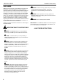
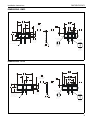
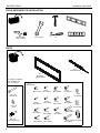
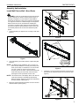
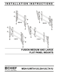
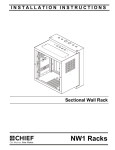
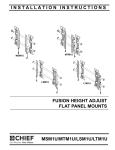
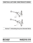
INSTALLATION INSTRUCTIONS
Istruzioni di installazione
Installatie-instructies
Instructions d´installation
Instrucciones de instalación
Installationsanleitung
Instruções de Instalação
RMF2
RLF2
RXF2
Universal Fixed Mounts
Spanish Product Description
German Product Description
Portuguese Product Description
Italian Product Description
Dutch Product Description
French Product Description
RMF2/RLF2/RXF2
RMF2/RLF2/RXF2
Installation Instructions
DISCLAIMER
Milestone AV Technologies and its affiliated corporations and
subsidiaries (collectively "Milestone"), intend to make this
manual accurate and complete. However, Milestone makes no
claim that the information contained herein covers all details,
conditions or variations, nor does it provide for every possible
contingency in connection with the installation or use of this
product. The information contained in this document is subject
to change without notice or obligation of any kind. Milestone
makes no representation of warranty, expressed or implied,
regarding the information contained herein. Milestone assumes
no responsibility for accuracy, completeness or sufficiency of
the information contained in this document.
WARNING: Use this mounting system only for its intended
Chief® is a registered trademark of Milestone AV Technologies.
All rights reserved.
IMPORTANT ! : The RMF2/RLF2/RXF2 mounts are designed
IMPORTANT SAFETY INSTRUCTIONS!
WARNING: A WARNING alerts you to the possibility of
serious injury or death if you do not follow the instructions.
CAUTION: A CAUTION alerts you to the possibility of
damage or destruction of equipment if you do not follow the
corresponding instructions.
WARNING: Failure to read, thoroughly understand, and
follow all instructions can result in serious personal injury,
damage to equipment, or voiding of factory warranty! It is the
installer’s responsibility to make sure all components are
properly assembled and installed using the instructions
provided.
WARNING: Failure to provide adequate structural strength
for this component can result in serious personal injury or
damage to equipment! It is the installer’s responsibility to
make sure the structure to which this component is attached
can support five times the combined weight of all equipment.
Reinforce the structure as required before installing the
component. The wall to which the mount is being attached
may have a maximum drywall thickness of 5/8" (1.6cm). Do
not install drywall anchors into the seam between drywall
pieces.
WARNING: Exceeding the weight capacity can result in
serious personal injury or damage to equipment! It is the
installer’s responsibility to make sure the combined weight of
all components attached does not exceed 125 lbs (56.7 kg)
for the RMF2 and RLF2 or 175 lbs (79.4 kg) for the RXF2.
Use with products heavier than the maximum weight
indicated may result in collapse of the mount and its
accessories causing possible injury.
2
use as described in these instructions. Do not use
attachments not recommended by the manufacturer.
WARNING: Never operate this mounting system if it is
damaged. Return the mounting system to a service center for
examination and repair.
WARNING: Do not use this product outdoors.
to be mounted to an 8" concrete, 8"x8"x16" concrete block, or
2" x 4" wood studs (16" on center) wall.
--SAVE THESE INSTRUCTIONS--
Installation Instructions
RMF2/RLF2/RXF2
DIMENSIONS - RMF2
558.8
22.00
[449]
17.68
MAX
279.4
11.00
200
7.87
TOP MOUNTING
HOLE TO CENTERLINE
ARROW ON THE
WALL PLATE
WALL PLATE
OPENING
8.7
.34
20.1
.79
(UP TO 1.54
USING SPACERS)
177.8
7.00
WALL PLATE
OPENING
419.1
16.50
25.4
1.00
212.7
8.38
400
15.75
MAX
ORIENTATION
AND CENTERLINE
NOTCHES
63.5
2.50
CENTERLINE
TO BOTTOM OF
WALL PLATE
OPENING
-KICKSTAND LANYARDS
-WHEN KICKSTAND
IS ACTIVATED, THE
DISPLAY TILTS BACK 5
7.1
.28
HOLE SIZE
FOR LOCK
CENTERLINE
DIAMOND
DETAIL A
SCALE 1 : 2
DETAIL B
SCALE 1 : 2
DIMENSIONS - RLF2
WALL PLATE
OPENING
781.1
30.75
[670]
26.38
MAX
390.5
15.38
419.1
16.50
200
7.87
TOP MOUNTING
HOLE TO CENTERLINE
ARROW ON THE
WALL PLATE
8.7
.34
20.1
.79
(UP TO 1.54
USING SPACERS)
177.8
7.00
WALL PLATE
OPENING
25.4
1.00
212.7
8.38
400
15.75
MAX
-KICKSTAND LANYARDS
-WHEN KICKSTAND
IS ACTIVATED, THE
DISPLAY TILTS BACK 5
63.5
2.50
CENTERLINE
TO BOTTOM OF
WALL PLATE
OPENING
ORIENTATION
AND CENTERLINE
NOTCHES
7.1
.28
HOLE SIZE
FOR LOCK
CENTERLINE
DIAMOND
DETAIL A
SCALE 1 : 2
DETAIL B
SCALE 1 : 2
3
RMF2/RLF2/RXF2
Installation Instructions
DIMENSIONS - RXF2
WALL PLATE
OPENING
965.2
38.00
[965.2]
38.00
MAX
482.6
19.00
200
7.87
TOP MOUNTING
HOLE TO CENTERLINE
ARROW ON THE
WALL PLATE
20.1
.79
(UP TO 1.54
USING SPACERS)
177.8
7.00
WALL PLATE
OPENING
8.7
.34
25.4
1.00
212.7
8.38
500
19.69
MAX
ORIENTATION
AND CENTERLINE
NOTCHES
63.5
2.50
CENTERLINE
TO BOTTOM OF
WALL PLATE
OPENING
-KICKSTAND LANYARDS
-WHEN KICKSTAND
IS ACTIVATED, THE
DISPLAY TILTS BACK 5
7.1
.28
HOLE SIZE
FOR LOCK
CENTERLINE
DIAMOND
DETAIL A
SCALE 1 : 2
DETAIL B
SCALE 1 : 2
4
Installation Instructions
RMF2/RLF2/RXF2
LEGEND
Tighten Fastener
Pencil Mark
Apretar elemento de fijación
Marcar con lápiz
Befestigungsteil festziehen
Stiftmarkierung
Apertar fixador
Marcar com lápis
Serrare il fissaggio
Segno a matita
Bevestiging vastdraaien
Potloodmerkteken
Serrez les fixations
Marquage au crayon
Loosen Fastener
Drill Hole
Aflojar elemento de fijación
Perforar
Befestigungsteil lösen
Bohrloch
Desapertar fixador
Fazer furo
Allentare il fissaggio
Praticare un foro
Bevestiging losdraaien
Gat boren
Desserrez les fixations
Percez un trou
Phillips Screwdriver
Adjust
Destornillador Phillips
Ajustar
Kreuzschlitzschraubendreher
Einstellen
Chave de fendas Phillips
Ajustar
Cacciavite a stella
Regolare
Kruiskopschroevendraaier
Afstellen
Tournevis à pointe cruciforme
Ajuster
Open-Ended Wrench
Remove
Llave de boca
Quitar
Gabelschlüssel
Entfernen
Chave de bocas
Remover
Chiave a punte aperte
Rimuovere
Steeksleutel
Verwijderen
Clé à fourche
Retirez
By Hand
Optional
A mano
Opcional
Von Hand
Optional
Com a mão
Opcional
A mano
Opzionale
Met de hand
Optie
À la main
En option
Hex-Head Wrench
Security Wrench
Llave de cabeza hexagonal
Llave de seguridad
Sechskantschlüssel
Sicherheitsschlüssel
Chave de cabeça sextavada
Chave de segurança
Chiave esagonale
Chiave di sicurezza
Zeskantsleutel
Veiligheidssleutel
Clé à tête hexagonale
Clé de sécurité
5
RMF2/RLF2/RXF2
Installation Instructions
TOOLS REQUIRED FOR INSTALLATION
7/32" (5.5mm)
5/16" (7.9mm)
1/2" (12.7mm)
#2
PARTS
B(2)
[vertical bracket]
A(1)
[wall plate]
[RLF2 shown]
For below kit, quantities
are 4 for RMF2 and
RLF2, 6 for RXF2
F (1)
Hardware Bag
FA(8)
M4 x 16mm
FE(6)
M5 x 16mm
FI(6)
M6 x 16mm
FL(6)
M8 x 20mm
FP(8)
1/4"(6.4mm)
C(4 or 6)
5/16 x 2 1/2"
FB(6)
M4 x 20mm
FF(6)
M5 x 20mm
FJ(6)
M6 x 25mm
FQ(8)
1/2"(12.7mm)
D(4 or 6)
5/16"
FC(6)
M4 x 25mm
E(4 or 6)
[concrete anchor]
6
FD(6)
M4 x 35mm
FM(6)
M8 x 30mm
FG(6)
M5 x 25mm
FH(6)
M5 x 35mm
FK(6)
M6 x 35mm
FN(6)
M8 x 40mm
FS(8)
FO(6) [universal washer]
M8 x 50mm
Installation Instructions
RMF2/RLF2/RXF2
Assembly And Installation
Install Wall Plate to Wall - Wood Studs
2
x 4 or 6
WARNING: Failure to provide adequate structural strength
for this component can result in serious personal injury or
damage to equipment! It is the installer’s responsibility to
make sure the structure to which this component is attached
can support five times the combined weight of all equipment.
Reinforce the structure as required before installing the
component. The wall to which the mount is being attached
may have a maximum drywall thickness of 5/8" (1.6cm). Do
not install drywall anchors into the seam between drywall
pieces.
1.
3
Unfold wall plate (A) to prepare it for mounting to wall. (See
Figure 1)
Figure 2
2 x 24"
1
(A)
2 x 16"
1
Figure 1
2.
3 x 16"
Level wall plate (A) and mark locations of pilot holes.(See
Figure 2)
CENTER
LINE
NOTE: The RMF2 must be installed on two 16" studs. The
RLF2 can be installed on 16" studs (inner holes) or 24"
studs (outer holes). For the RXF2, it can be mounted
over two or three 16" studs or two 24" studs. If
mounting to three 16" studs, it must be mounted to all
three studs using the outer holes and center holes.
(See Figures 2 and 3) All studs must be 2"x4".
Figure 3
4.
Install 5/16 x 2 1/2" hex head cap screws (C) through four
flat washers (D), wall plate (A) and into wood studs. (See
Figure 4)
NOTE: The vertical center of the display will be even with the
center line indicated on the labels located directly
below each hinge. Keep this in mind when determining
mounting location. (See Figure 3)
3.
(D) x 4 or 6
Drill 7/32" (5.5mm) diameter pilot holes into wood studs at
marked locations. (See Figure 2)
4
(C) x 4 or 6
(A)
Figure 4
7
RMF2/RLF2/RXF2
Installation Instructions
Install Wall Plate to Wall - Concrete or
Concrete Block
WARNING: Failure to provide adequate structural strength
for this component can result in serious personal injury or
damage to equipment! It is the installer’s responsibility to
make sure the structure to which this component is attached
can support five times the combined weight of all equipment.
Reinforce the structure as required before installing the
component. The wall to which the mount is being attached
may have a maximum drywall thickness of 5/8" (1.6cm).
3.
Drill 5/16" (8mm) diameter pilot holes into wall at marked
locations. Holes must be drilled at least 3 1/4 inches deep.
(See Figure 5)
4.
Install four or six concrete anchors (E) into drilled holes. Use
a hammer to tap anchors into holes. (See Figures 6 and 7)
IMPORTANT ! : The anchors must be installed through
any wall covering until flush with the concrete wall. (See
Figure 6)
concrete
wall
Pilot Hole 5/16 x 3 1/4"
(M8 x 82.5mm)
(D)
WARNING: ELECTRICAL SHOCK HAZARD! CUTTING
OR DRILLING INTO ELECTRICAL CORDS OR CABLES
CAN CAUSE DEATH OR SERIOUS PERSONAL INJURY!
ALWAYS make certain area behind mounting surface is free
of electrical wires and cables before drilling or installing
fasteners.
(C)
Anchor (E)
WARNING: EXPLOSION AND FIRE HAZARD! CUTTING
OR DRILLING INTO GAS PLUMBING CAN CAUSE DEATH
OR SERIOUS PERSONAL INJURY! ALWAYS make certain
area behind mounting surface is free of gas, water, waste, or
any other plumbing before cutting, drilling, or installing
fasteners.
1.
Unfold wall plate (A) to prepare it for mounting to wall. (See
Figure 1)
2.
Level wall plate (A) and mark locations of pilot holes at
desired mounting location. (See Figure 5)
IMPORTANT ! : The RMF2-RLF2-RXF2 mounts are
designed to be mounted to 8" concrete or 8"x8"x16"
concrete block.
Anchor
flush with
concrete
wall
(A)
wall covering
Figure 6
5.
Using 1/2" (12.7mm) wrench, install screws (C) through flat
washers (D), wall plate (A) and into concrete anchors (E).
(See Figure 7)
NOTE: For the RLF2, either the inner or outer four holes may
be used.
4
(E) x 4 or 6
NOTE: For the RXF2, use the outer four holes and the two
middle holes on wall plate for installation.
(D) x 4 or 6
NOTE: The vertical center of the display will be even with the
center line indicated on the labels located directly
below each hinge. Keep this in mind when determining
mounting location. (See Figure 5)
2
x 4 or 6
3
CENTER
LINE
5
Figure 5
8
(C) x 4 or 6
(A)
Figure 7
Installation Instructions
RMF2/RLF2/RXF2
Install Brackets to Display
(non-recessed holes)
WARNING: The minimum hole pattern size is 100mm x
100mm for the RMF2 and 200mm x 200mm for the RLF2 and
the RXF2.
1.
(FA-FO) x4,x6,x8
6
(FS) x4,x6,x8
Lay display face down on protective surface.
2
4
CAUTION: Using screws of improper diameter may
damage your display! Proper screws will easily thread into
display mounting holes.
2.
Select screw diameter by examining hardware (FA-FO)
(8mm, 6mm, 5mm, or 4mm) and comparing with mounting
holes on display. (See Figure 8)
3.
Select spacers: (See Figure 8)
•
•
•
If mounting holes are not recessed and both
brackets (B) can lay flat against display, then no
spacers are required.
If mounting holes are recessed, or if protrusions
prevent brackets (B) from laying flat, then spacers
(FP or FQ) must be used.
If additional depth is needed behind display,
spacers (FP and FQ) can be stacked on top of
each other.
CAUTION: Using screws of improper length may damage
your display! Proper screws will have adequate thread
engagement without contacting bottom of display mounting
holes.
4.
(B) x 2
(recessed holes or
extra depth needed)
(FA-FO) x4,x6,x8
(FS) x4,x6,x8
6
2
4
3 (FP or FQ)*
Select screw length: (See Figure 8)
•
•
5.
5
Using your hand, insert SHORTEST length screw
of selected diameter (FA, FE, FI or FL) through
bracket (B), universal washer (FS), selected
spacer (FP or FQ, if required), into display
mounting hole. Do NOT thread screw into hole at
this time.
Proper screw length requires base of screw head
to protrude above flat washer a distance equal to
or greater than the screw diameter. If screw
length is inadequate, select longer screw. Select
shortest screw which will protrude the required
distance.
5
(B) x 2
Place brackets (B) on display, ensuring: (See Figure 8)
•
•
Upper hooks are towards top of display.
Center of brackets (B) are as close to the center
of the back of display as possible after being
installed. Center of bracket is indicated by the
diamond-shaped hole.
6.
Using Phillips screwdriver, carefully install selected screws
through universal washers (FS), brackets (B), and spacers
(FP or FQ, if required), into display. (See Figure 8)
7.
Tighten all screws. Ensure all applicable display mounting
holes (4, 6, or 8) are used.
*If additional depth is needed,
spacers (FP or FQ) can be
stacked on top of each other
Figure 8
9
RMF2/RLF2/RXF2
Installation Instructions
Install Display to Wall Plate
(view from left side)
WARNING: Exceeding the weight capacity can result in
serious personal injury or damage to equipment! It is the
installer’s responsibility to make sure the combined weight of
all components attached does not exceed 125 lbs (56.7 kg)
for the RMF2 and RLF2 or 175 lbs (79.4 kg) for the RXF2.
Use with products heavier than the maximum weight
indicated may result in collapse of the mount and its
accessories causing possible injury.
2
WARNING: Display may be very heavy! Ensure display
can be safely lifted and maneuvered as required to install on
wall plate. Failure to take adequate precautions can result in
serious personal injury or damage to equipment!
kickstand engaged
WARNING: Interface brackets must be hung on opposite
sides of the center tab on wall plate! (See Figure 9)
center tab
1
5
interface brackets
must be hung on opposite
sides of center tab
Figure 10
NOTE: Any cable management or rear display adjustments
should be made when the display is resting on the
kickstand.
Figure 9
1.
Make sure interface brackets are in the kickstand position
by pulling down on handles as far as possible. (See Figure
10)
2.
Hang display with brackets (B) on upper rail of wall plate (A).
Kickstand should be engaged with lower portion of wall
plate. (See Figure 10)
10
Installation Instructions
RMF2/RLF2/RXF2
(views from left side)
kickstand
against wall
locked
position
3
4
6
Figure 11
3.
Unlock kickstand by pushing up on interface brackets until
kickstand rests against the wall. (See Figure 11)
4.
Push up on the interface brackets further in order to lock
display into position against wall. (See Figure 11)
5.
Straps can be tucked behind display on notch on interface
brackets (B) after installation is complete so that they will
not be visable to the viewer. (See Figure 9)
6.
(Optional) Route padlock or cable lock (not included)
through bottom holes on interface bracket to provide
additional security. (See Figure 11)
11
RMF2/RLF2/RXF2
Installation Instructions
USA/International
Europe
Chief Manufacturing, a products division
of Milestone AV Technologies
8800-002426 Rev00
2013 Milestone AV Technologies, a
Duchossois Group Company
www.chiefmfg.com
11/13
Asia Pacific
A
P
F
A
P
F
A
6436 City West Parkway, Eden Prairie, MN 55344
800.582.6480 / 952.225.6000
877.894.6918 / 952.894.6918
Franklinstraat 14, 6003 DK Weert, Netherlands
+31 (0) 495 580 852
+31 (0) 495 580 845
Office No. 1 on 12/F, Shatin Galleria
18-24 Shan Mei Street
Fotan, Shatin, Hong Kong
P 852 2145 4099
F 852 2145 4477