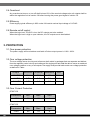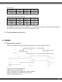
1
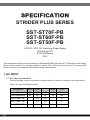
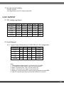
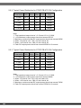
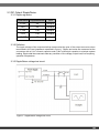
STRIDER PLUS SERIES
ST50F-PB
ST60F-PB
ST70F-PB
Unparalleled combination of power,
efficiency and flexibility
High efficiency with 80 PLUS Bronze certification
24/7 continuous power output with 40 C operating temperature
100% modular cables
Class-leading single +12V rail
Strict ±3% voltage regulation and low ripple & noise
PCI-E 8/6pin connectors support
Silent running 120mm fan with 18dBA
o
Installation and system optimization guide:
The following manual and guides were carefully prepared by the SilverStone engineering team to
help you maximize the potential of your SilverStone product. Please keep this manual for future
reference when upgrading or performing maintenance on your system. A copy of this manual can also
be downloaded from our website at:
Specification
P.1
AC INPUT
P.1
DC OUTPUT
P.2
Protection
P.5
Timing
P.6
Environment
P.8
Safety
P.8
Electromagnetic Compatibility (EMC)
P.9
MTBF
P.9
Mechanical Requirements
P.9
SPECIFICATION
STRIDER PLUS SERIES
SST-ST70F-PB
SST-ST60F-PB
SST-ST50F-PB
ATX12V / EPS 12V Switching Power Supply
With Active PFC
80 PLUS Bronze
PS/2
This specification describes the requirements of 500W/600W/700W with active P.F.C Switching Power Supply
with an ATX form-factor,+5V standby voltage, fan control, ATX 12V Power supply version 2.3, remote on/off
control, dual line input capability and forced air cooling characteristics.
1. AC INPUT
1.1 AC input requirements
The input voltage, current, and frequency requirements for continuous operation are stated below.
Table 1 AC Input Line Requirements
01
Parameter
Min
Nom
Max
Unit
Vin
90
100
240
264
VACrms
Vin Frequency
47
60
50
63
Hz
Iin(ST50F-PB)
-
8.0
4.0
-
A
Iin(ST60F-PB)
-
9.0
4.5
-
A
Iin(ST70F-PB)
-
10
5.0
-
A
1.2 Inrush current limiting
50 A @ 115Vrms
100 A @ 230Vrms (at 25 C ambient cold start)
o
2. DC OUTPUT
2.1 DC voltage regulation
Parameter Range
+3.3V
+/-3%
Min
Nom
Max
Unit
+3.14
+3.3
+3.47
Volts
+5.0
+5V
+/-3%
+4.75
+5.25
Volts
+12V
+/-3%
+11.40
+12.0 +12.6
Volts
-12V
+/-10%
-10.80
-12.0
-13.2
Volts
+5VSB
+/-5%
+4.75
+5.0
+5.25
Volts
2.2 Load Ranges
2.2.1 Typical Power Distribution for ST50F-PB ATX12V Configuration
Parameter Min Nom. Max Peak
Unit
+3.3V
0.1
-
18
-
Amps
+5V
0.2
-
16
-
Amps
+12V
0.5
-
38
-
Amps
-12V
0.0
-
0.3
-
Amps
+5VSB
0.0
-
2.5
-
Amps
Note:
1. Total combined output load of +3.3V and +5V is ≦110W.
2. +12V Maximum output power should not exceed 456W.
3. When +5V load is over 15A,+12V min load is 2A.
4. When +12V load is over 30A,+5V min load is 4A.
5. Maximum continuous total DC output power should not exceed 500W.
6. Peak DC output power should not exceed 550W for 12 second.
02
2.2.2 Typical Power Distribution for ST60F-PB ATX12V Configuration
Parameter Min Nom
Max Peak
Unit
+3.3V
0.1
-
20
-
Amps
+5V
0.2
-
17
-
Amps
+12V
0.5
-
46
-
Amps
-12V
0.0
-
0.3
-
Amps
+5VSB
0.0
-
2.5
-
Amps
Note:
1. Total combined output load of +3.3V and +5V is ≦120W.
2. +12V Maximum output power should not exceed 552 W.
3. Maximum continuous total DC output power should not exceed 600W.
4. When +5V load is over 15A,+12V min load is 2A.
5. When +12V load is over 30A,+5V min load is 4A.
6. Peak DC output power should not exceed 650W for 12 second.
2.2.3 Typical Power Distribution for ST70F-PB ATX12V Configuration
Parameter Min Nom
Max Peak
Unit
+3.3V
0.1
-
22
-
Amps
+5V
0.2
-
18
-
Amps
+12V
0.5
-
54
-
Amps
-12V
0.0
-
0.3
-
Amps
+5VSB
0.0
-
2.5
-
Amps
Note:
1. Total combined output load of +3.3V and +5V is ≦130W.
2. +12V Maximum output power should not exceed 648W.
3. When +5V load is over 15A,+12V min load is 2A.
4. When +12V load is over 30A,+5V min load is 4A.
5. Maximum continuous total DC output power should not exceed 700W.
6. Peak DC output power should not exceed 750W for 12 second.
03
2.3 DC Output Ripple/Noise.
2.3.1 Ripple regulation
Parameter Ripple&Noise
Unit
+3.3V
50
mVp-p
+5V
50
mVp-p
+12V
120
mVp-p
-12V
120
mVp-p
+5VSB
50
mVp-p
2.3.2 Definition
The ripple voltage of the outputs shall be measured at the pins of the output connector when
terminated in the load impedance specified in figure 1. Ripple and noise are measured at the
connectors with a 0.1uF ceramic capacitor and a 10uF electrolytic capacitor to simulate system
loading. Ripple shall be measured under any condition of line voltage, output load, line frequency,
operation temperature.
2.3.3 Ripple/Noise voltage test circuit
Figure 3. Ripple/Noise voltage test circuit
04
2.4 Overshoot
Any overshoot at turn on or turn off shall be less 10% of the nominal voltage value, all outputs shall be
within the regulation limit of section 2.0 before issuing the power good signal of section 5.0.
2.5 Efficiency
Power supply typical efficiency is 82% under full Load at nominal input voltage of 115VAC.
2.6 Remote on/off control
When the logic level "PS-ON" is low, the DC outputs are to be enabled.
When the logic level is high or open collector, the DC outputs are to be disabled.
3. PROTECTION
3.1 Over-power protection
The power supply will be shutdown and latch off when output power is 110%~160%.
3.2 Over voltage protection
The over voltage sense circuitry and reference shall reside in packages that are separate and distinct
from the regulator control circuity and reference.No single point fault shall be able to cause a sustained
over voltage condition on any or all outputs.The supply shall provide latch-mode over voltage protection
as defined in Table.
Output
Minimum
Nominal
+12 VDC
13.4
+5 VDC
5.74
+3.3 VDC
3.76
Maximum
Unit
15.0
17
Volts
6.3
7.5
Volts
4.2
4.8
Volts
3.3 Over Current Protection
ST50F-PB
Parameter
Min.
Max.
Unit
+12V
52
65
A
Parameter
Min.
Max.
Unit
+12V
55
70
A
ST60F-PB
05
ST70F-PB
Parameter
Min.
Max.
Unit
+12V
60
80
A
ST50F-PB, ST60F-PB, ST70F-PB
Parameter
Min.
Max.
Unit
+3.3V
24
40
A
+5V
24
40
A
No damage or hazardous condition should occur with all the DC output connectors disconnected from
the load. The power supply may latch into the shutdown state.
3.4 Over temperature protection
4. TIMING
4.1 Signal timing drawing
Figure 4 is a reference for signal timing for main power connector signals and rails.
Figure 4. PS-OK Timing Sequence
(1)T2: Rise time (0.1ms~20ms)
(2)T3: Power good turn on delay time (100ms~500ms)
(3)T4: Power good turn off delay time (1ms min)
(4)T5: Rise time (10ms max)
06
4.2 .Output Transient Response
Table 13. summarizes the expected output transient step sizes for each output.
The transient load slew rate is =1.0A/us.
DC Output Transient Step Sizes
Max.step size
Max.step size
Output
(% of rated output amps per Sec 3.2.3)*
(amps)
+12 VDC
40%
-
+5 VDC
30%
-
+3.3 VDC
30%
-
-12 VDC
-
0.1A
+5 VSB
-
0.5A
* For example, for a rated +5 VDC output of 18A,the transient step would be 30% x 18A=5.4A
Output voltages should remin within the remain within the regulation limits of Section 2.1,and the power
supply should stable when subjected to load transients per Table 13. from any steady state load,
including any or all of the following conditions:
Simultaneous load steps on the +12 VDC,+5 VDC,and +3.3 VDC outputs
(all steps occurring in the same direction)
Load-changing repetition rate of 50 Hz to 10 kHz
AC input range per Section 1.0
+5Vsb Loading min 0.1A
+12V loading min 0.6A
4.3 Hold up time (T6 of figure 4.)
When the power loss its input power, The output shall maintain 12ms in regulation ranges Tested at
80% of maximum load and AC:115V/60Hz or 230V/50Hz.
4.4 Capacitive Load-REQUIRED
The power supply should be able to power up and operate with the regulation limits defined in Table
15,With the following capacitances simultaneously present on the DC outputs.
Output Capacitive Loads
07
Output
Capacitive Load(uF)
+12VDC
10000
+5VDC
10000
+3.3VDC
10000
+5VSB
6000
-12VDC
330
5. ENVIRONMENT
5.1 Operation
o
Temperature
Relative Humidity
o
0 C to 40 C
at AC 100V full Load
20 to 85%, non-condensing
5.2 Shipping and Storage
o
Temperature
-10 TO 50 C
Relative Humidity
5 to 90%, non-condensing
5.3 Altitude
Temperature
3,000FT max.
Relative Humidity
15,000FT max.
6. SAFETY
6.1 Underwriters Laboratory (UL) recognition.
The power supply designed to meet UL 60950.
6.2 The power supply must be certified to EN 60950-1.
6.3 The power supply must bear the German Bauart Mark from Nemko.
6.4 NEMKO certified by any NORDIC .
08
7. ELECTROMAGNETIC COMPATIBILITY (EMC)
7.1 ELECTROSTATIC DISCHARGE (ESD) - EN 61000 – 4 - 2:2008
7.2 ELECTRICAL FAST TRANSIENT / BURST ( EFT/B) – EN 61000 – 4 - 4:2010
7.3 SURGE – EN 61000 – 4 - 5:2005
7.4 POWER FREQUENCY MAGNETIC FIELD – EN 61000 – 4 - 8:2009
7.5 VOLTAGE DIPS – RN 61000 – 4 - 11:2004
7.6 RADIATED SUSCEPTIBILTY – EN 61000 – 4 – 3 :2006
7.7 CONDUCTED SUSCEPTIBILTY – EN 61000 – 4 - 6:2008
7.8 VOLTAGE FLUCTATION - EN 61000 – 3 – 3 :2008
7.9 EN61000-3-2 harmonic current emissions.
If applicable to sales in Europe, the power supply shall meet the requirements ofEN 61000-3-2 Class D
and the Guidelines for the Suppression of Harmonics in Appliances and General Use Equipment Class D
for harmonic line current content at full-rated power.
7.10 EN55022 Class B Radio interference (CISPR 22).
7.11 FCC Part 15, Subpart J class B 115VAC operation.
8. MTBF
8.1 MTBF (MEAN TIME BETWEEN FAILURES) CALCULATION
The demonstrated MTBF shall be 100,000 hours of continuous operation at 25oC,full load, 80% confidence
limit and nominal line. The MTBF of the power supply shall be calculated in accordance with MIL-STD-217D/E.
The DC FAN is not included.
9. MECHANICAL REQUIREMENTS
150 mm (W) × 86 mm (H) × 140mm (D)
09
G11222620