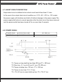
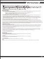
1
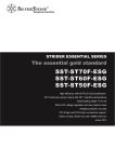
SST-ST30SF
The reference SFX power supply
Support standard SFX form factor and ATX via included bracket
300W continuous power output at 50℃ operating temperature rated for 24/7 operation
80 PLUS Bronze level efficiency (82%~85% efficiency at 20%~100% loading)
Class-leading single +12V rail with 22A
Intelligent semi-fanless operation
Silent running 80mm fan with 18dBA minimum
Single PCI-E 6pin connectors support
Active PFC
SFX Form Factor
SST-ST30SF
300W Switching Power Supply
Active PFC Circuit
Full Range Input
1. GENERAL DESCRIPTION AND SCOPE
This is the specification of Model SST-ST30SF; AC-line powered switching power
supply with active PFC (Power Factor Correction) circuit, meet EN61000-3-2. Also,
5Vsb power is less than 0.5Winput at power off mode (PS_ON input at high state)
which is comply with ErP Lot 6 year 2013 requirement.
The specification below is intended to describe as detailedly as possible the functions and performance of the subject power supply. Any comment or additional
requirements to this specification from our customers will be highly appreciated and
treated as a new target for us to approach.
2. REFERENCE DOCUMENTS
The subject power supply will meet the EMI requirements and obtain main safety
approvals as following:
2.1. EMI REGULATORY
FCC: FCC Part 15, Subpart B, Class B
-CISPR 22: 1997, Class B
-ICES-003: 2004, Class B
-ANSI C63.4-2003
EMC: EN55022: 2006+AI: 2007, Class B
EN 61000-3-2: 2007, Class D
EN 61000-3-3: 2008
CISPR 22: 2005+A1: 2005, Class B
AS/NZS CISPR 22: 2006, Class B
2.2. SAFETY
CB: IEC 60950~1:2005(2nd Edition) and/or EN 60950~1:2006 +A11:2009
UL: UL 60951-1 , 2nd Edition, 2007-03-27
TUV: EN 60950-1:2006+All
3. INPUT ELECTRICAL SPECIFICATIONS
3.1. AC INPUT
Parameter
(1)
Mi n.
Nom.
Max.
Unit
Vin (115VAC)
90
115
132
VAC rms
Vin (230VAC)
180
230
264
VAC rms
Vin Frequency
47
--
63
HZ
◆ Nominal voltages for test purposes are considered to be within ±1.0V of nominal.
3.2. INRUSH CURRENT
Maximum inrush current from power-on (with power on at any point on the AC sine)
and including, but not limited to, three line cycles, shall be limited to a level below
the surge rating of the input line cord, AC switch if present, bridge rectifier, fuse, and
EMI filter components. Repetitive ON/OFF cycling of the AC input voltage should not
damage the power supply or cause the input fuse to blow.
3.3. INPUT LINE CURRENT & POWER FACTOR (P.F.)
(At Full load)
AC input
Input line current
P.F.@ Full Load
P.F.@ Pin=75W
115V
< 3.5 Amps – rms
> 0.95
> 0.8
230V
< 2.0 Amps – rms
> 0.9
> 0.65
3.4. EFFICIENCY
3.4.1 General
Under the load conditions defined in Table 1. and Table 2. The loading condition for
testing efficiency shown in Table 1 represents a fully loaded system. ~ 50% (typical)
loaded system. and ~ 20% (light) loaded system.
Table 1. Loading Table for Efficiency
Measurements
300W(loading shown in Amps)
Loading
+12V
+5V
+3.3V
-12V
+5Vsb
Full
18.7
7.58
7.96
0.31
1.56
Typical
9.3
3.79
3.98
0.16
0.78
Light
3.7
1.52
1.59
0.06
0.31
Table 2. Minimum Efficiency Vs Load
Loading
Voltage
Full load
Typical load
Light load
Required Minimum Efficiency
115V
>82%
>85%
>82%
Required Minimum Efficiency
230V
>85%
>87%
>85%
◆ Minimum Efficiency for test purposes are considered to be within ±1.0% of nominal.
3.4.2 Standby Power Consumption (+5Vsb):
Input Power < 0.5W @+ 5Vsb/45mA & 230Vac input
PS_ON input signal @ High State
4 . OUTPUT ELECTRICAL REQUIREMENTS
4.1. OUTPUT VOLTAGE AND CURRENT RATING
Output
MINIMUM
NORMAL
MAXIMUM
PEAK
LOAD
LINE
LOAD
LOAD
LOAD
LOAD
REG
REG
RIPPLE & NOISE
+3.3V
0.1A
10.5A
21A
±5%
±1%
50mV P-P
+5V
0.2A
10A
20A
±5%
±1%
50mV P-P
+12V
0.5A
8A
22A
±5%
±1%
120mV P-P
-12V
0A
0.25A
0.5A
±10%
±1%
120mV P-P
+5VSB
0A
1.25A
2.5A
±5%
±1%
50mV P-P
3A
( 1 ) +3.3V & 5V total output not exceed 103W.
( 2 ) Total output continuous shall not exceed 300W watts.
( 3 )+5Vsb peak current is 3A(less then 500m sec.) , minimum voltage during peak is > 4.5Vdc.
( 4 )Voltages and ripple are measured at the load side of mating connectors with a 0.1 uF
monolithic ceramic capacitor paralleled by a 10 uF electrolytic capacitor across the measuring terminals.
4.2. LOAD CAPACITY SPECIFICATIONS
The cross regulation defined as follows, the voltage regulation limits DC include
DC Output ripple & noise.
LOAD
+3.3V
+5V
+12V
-12V
+5VSB
condition_1
X
X
X
X
2.5A
condition_2
0.1A
1.5A
0.6A
0A
0A
condition_3
1.5A
0.2A
0.6A
0.5A
0A
condition_4
1A
10A
16A
0.1A
0.1A
condition_5
1A
14A
4A
0.1A
0.1A
condition_6
0.9A
20A
15.7A
0.3A
1A
condition_7
18A
2A
2A
0A
0.1A
condition_8
21A
6.74A
15.7A
0.3A
1A
CL-Test-1
12.4A
12.4A
1A
0.1A
0.1A
CL-Test-2
12.4A
12A
0.8A
0.1A
0.1A
CL-Test-3
1A
1A
22A
0.1A
0.1A
CL-Test-4
0.6A
0.6A
22A
0.1A
0.1A
4.3. HOLD-UP TIME (@Typical load of Table 1.)
115V / 60Hz : 17 m sec. minimum.
230V / 50Hz : 17 m sec. minimum.
The output voltage will remain within specification, in the event that the input
power is removed or interrupted, for the duration of one cycle of the input
frequency. The interruption may occur at any point in the AC voltage cycle.
The power good signal shall remain high during this test.
4.4. OUTPUT RISE TIME
(10% TO 95% OF FINAL OUTPUT VALUE, @FULL LOAD)
115V-rms or 230V-rms
+ 3.3Vdc : 20ms Maximum
+ 5Vdc : 20ms Maximum
+ 12Vdc : 20ms Maximum
+ 5Vsb : 20ms Maximum
- 12Vdc : 20ms Maximum
4.5. OVER VOLTAGE PROTECTION
Voltage Source
Protection Point
+3.3V
3.76V-4.8V
+5V
5.6V-7.0V
+12V
13.0V-16.5V
4.6. OVER CURRENT PROTECTION
OUTPUT VOLTAGE
Max. over current limit
+3.3V
60A
+5V
48A
+12V
30A
4.7. SHORT CIRCUIT PROTECTION
Output short circuit is defined to be a short circuit load of less than 0.1 ohm.
In the event of an output short circuit condition on +3.3V, +5V, +12V or –12V output,
the power supply will shutdown and latch off without damage to the power supply.The
power supply shall return to normal operation after the short circuit has been removed
and the power switch has been turned off for no more than 2 seconds.
4.8. POWER SIGNAL
POWER GOOD
@115/230V,FULL LOAD
100 –500m sec.
POWER FAIL
@115/230V,FULL LOAD
1m sec. minimum
Figure:
T1: Power-on time shall be less than 500 ms (T1 < 500 ms).
T2: Rise time : 0.1 ms to 20 ms (0.1 ms ≤T2 ≤20 ms).
T3: Power-ok delay time: 100 ms < T3 < 500 ms
T4: Power-ok rise time: T4 ≦ 10 ms
T5 + T6: AC loss to output hold-up time :T5 + T6 ≥17 ms
4.9. The main power supply shall be off when the PS_ON pin is floating
(open collector). The ON/STBY pin of P1 must remain off state for 5 Sec
(maximum) prior to switching to the ON state
5. FAN NOISE REQUIREMENTS
5.1.The subject power supply is cooled by a self-contained, 80mm×15mm,
12VDC fan.
6. ENVIRONMENTAL REQUIREMENTS
The power supply will be compliant with each item in this specification for the
following Environmental conditions.
6.1. TEMPERATURE RANGE
Operating
+10 to +50 deg. C
Storage
-20 to +80 deg. C
6.2. HUMIDITY
Operating
5 –95% RH, Non-condensing
Storage
5 –95% RH, Non-condensing
6.3. VIBRATION
The subject power supply will withstand the following imposed conditions
without experiencing non-recoverable failure or deviation from specified output
characteristics.
Vibration Operating – Sine wave excited, 0.25 G maximum acceleration, 10-250
Hz swept at one octave / min. Fifteen minute dwell at all resonant points, where
resonance is defined as those exciting frequencies at which the device under
test experiences excursions two times large than non-resonant excursions.
Plane of vibration to be along three mutually perpendicular axes.
6.4. GROUND LEAKAGE CURRENT
The power supply ground leakage current shall be less than 3.5 mA.
6.5. RELIABILITY
The power supply reliability, when calculated by MIL-HDBK-217;latest revision,
are exceed 100,000 hours with all output at Typical load and an ambient
temperature of 25℃.
6.6. DIELECTRIC STRENGTH
Primary to Frame Ground : 1800 Vac for 1 sec.
Primary to Secondary : 1800Vac for 1 sec
6.7. INSULATION RESISTANCE
Primary to Frame Ground : 20 Meg.ohms Minimum
Primary to Secondary : 20 Meg.ohms Minimum
7. MECHANICAL REQUIREMENTS
7.1 Physical Dimension
125 mm (W) × 63.5 mm (H) × 100mm (D)
7.2 Connectors
M/B 24PIN connector
Orange
Blue
Black
Green
Black
Black
Black
White
Red
Red
Red
Black
Signal
Pin
Pin
Signal
+3.3V
-12VDC
COM
PS-ON
COM
COM
COM
N/C
+5VDC
+5VDC
+5VDC
COM
13
14
15
16
17
18
19
20
21
22
23
24
1
2
3
4
5
6
7
8
9
10
11
12
+3.3V
+3.3V
COM
+5VDC
COM
+5VDC
COM
PWRGOOD
+5Vsb
+12V
+12V
+3.3V
Orange
Orange
Black
Red
Black
Red
Black
Grey
Purple
Yellow
Yellow
Black
EPS 12V 8PIN connector
Yellow
Yellow
Yellow
Yellow
Signal
Pin
Pin
Signal
+12V
+12V
+12V
+12V
5
6
7
8
1
2
3
4
COM
COM
COM
COM
Black
Black
Black
Black
ATX 12V 4PIN (4+4PIN EPS 12V in split mode)
Signal
GND
GND
Black
Black
Pin
1
2
4PIN peripheral connector (HDD)
Signal
+12V
+12V
Yellow
Yellow
4PIN floppy connector (FDD)
Signal
+12V
COM
COM
+5VDC
Pin
1
2
3
4
SATA connector
Signal
Orange
+3.3V
Black
COM
Red
+5V
COM
Black
+12V
Yellow
Pin
5
4
3
2
1
Yellow
Black
Black
Red
Pin
3
4
Pin
1
2
3
4
Signal
+5VDC
COM
COM
+12V
Red
Black
Black
Yellow
6PIN PCI Express connector
Yellow
Yellow
Yellow
Signal
Pin
Pin
Signal
+12V
+12V
+12V
1
2
3
4
5
6
COM
COM
COM
Black
Black
Black
Warranty Information
Warranty terms & conditions
1.Product component defects or damages resulted from defective production is covered under warranty. Defects or damages with the following conditions will be fixed
or replaced under SilverStone Technology’s jurisdiction.
a)Usage in accordance with instructions provided in this manual, with no misuse, overuse, or other inappropriate actions.
b)Damage not caused by natural disaster (thunder, fire, earthquake, flood, salt, wind, insect, animals, etc…)
c)Product is not disassembled, modified, or fixed. Components not disassembled or replaced.
d)Warranty mark/stickers are not removed or broken.
Loss or damages resulted from conditions other than ones listed above are not covered under warranty.
2.Under warranty, SilverStone Technology’s maximum liability is limited to the current market value for the product (depreciated value, excluding shipping,handling, and
other fees). SilverStone Technology is not responsible for other damages or loss associated with the use of product.
3.Under warranty, SilverStone Technology is obligated to repair or replace its defective products. Under no circumstances will SilverStone Technology be liable for
damages in connection with the sale, purchase, or use including but not limited to loss of data, loss of business, loss of profits, loss of use of the product or incidental or
consequential damage whether or not foreseeable and whether or not based on breach of warranty, contract or negligence, even if SilverStone Technology has been
advised of the possibility of such damages.
4.Warranty covers only the original purchaser through authorized SilverStone distributors and resellers and is not transferable to a second hand purchaser
5.You must provide sales receipt or invoice with clear indication of purchase date to determine warranty eligibility.
6.If a problem develops during the warranty period, please contact your retailer/reseller/SilverStone authorized distributors or SilverStone http://www.silverstonetek.com
Please note that: (i) You must provide proof of original purchase of the product by a dated itemized receipt; (ii) You shall bear the cost of shipping (or otherwise transporting)
the product to SilverStone authorized distributors. SilverStone authorized distributors will bear the cost of shipping (or otherwise transporting) the product back to you after
completing the warranty service; (iii) Before you send the product, you must be issued a Return Merchandise Authorization (“RMA”) number from SilverStone. Updated warranty
information will be posted on SilverStone’s official website. Please visit http://www.silverstonetek.com for the latest updates.
Additional info & contacts
For North America ([email protected])
SilverStone Technology in North America may repair or replace defective product with refurbished product that is not new but has been functionally tested. Replacement
product will be warranted for remainder of the warranty period or thirty days, whichever is longer. All power supplies should be sent back to the place of purchase if it is
within 30 days of purchase, after 30 days, customers need to initiate RMA procedure with SilverStone Technology in USA by first downloading the “USA RMA form for
end-users” form from the below link and follow its instructions.
For Australia only ([email protected])
Our goods come with guarantees that cannot be excluded under the Australian Consumer Law. You are entitled to a replacement or refund for a major failure and for
compensation for any other reasonably foreseeable loss or damage. You are also entitled to have the goods repaired or replaced if the goods fail to be of acceptable
quality and the failure does not amount to a major failure. Please refer to above “Warranty terms & conditions” for further warranty details.
For Europe ([email protected])
For all other regions ([email protected])
Warranty length
For North America and Australia
All SilverStone retail PSU have from the date of purchase, 3 years limited warranty (some PSU carry a 1 or 5 year warranty)
For further information please visit: http://www.silverstonetek.com
For Europe
All SilverStone retail PSU have from the date of purchase, 3 years limited warranty (some PSU carry a 2 or 5 year warranty)
For further information please visit: http://www.silverstonetek.com
For all other regions
Please contact your local SilverStone authorized dealer or distributors for more information.
Note
SilverStone reserve the right to alter the above warranty information. Please visit http://www.silverstonetek.com for the latest update of the warranty information
April, 2013
G11219230