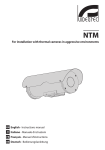
1
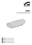
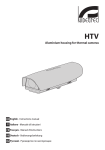
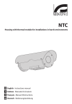
HTV
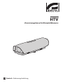
Aluminium housing for thermal cameras
EN English - Instructions manual
IT Italiano - Manuale di istruzioni
FR Francais - Manuel d'instructions
DE Deutsch - Bedienungslanleitung
HTV
Aluminium housing for thermal cameras
EN English - Instructions manual
Contents
EN - English - Instructions manual
ENGLISH
1 About this manual......................................................................................................... 3
1.1 Typographical conventions................................................................................................................................. 3
2 Notes on copyright and information on trademarks................................................. 3
3 Safety rules.................................................................................................................... 3
4 Identification................................................................................................................. 3
4.1 Product description and type designation.................................................................................................... 3
4.2 Product markings.................................................................................................................................................... 3
5 Preparing the product for use...................................................................................... 4
5.1 Contents and unpacking...................................................................................................................................... 4
5.2 Safely disposing of packaging material.......................................................................................................... 4
6 Installing and assembling............................................................................................. 4
6.1 Installation................................................................................................................................................................. 4
6.1.1 How to open the housing.................................................................................................................................................... 4
6.1.2 Camera installation................................................................................................................................................................. 4
6.1.3 Heater installation................................................................................................................................................................... 5
6.1.4 Camera power supply installation.................................................................................................................................... 5
6.1.5 Changing the germanium glass........................................................................................................................................ 6
6.1.5.1 Limits to use................................................................................................................................................................................................... 6
7 Maintaining and cleaning............................................................................................. 7
7.1 Cleaning IR glass and plastic parts.................................................................................................................... 7
8 Disposal of waste materials.......................................................................................... 7
9 Technical specifications................................................................................................ 7
9.1 General........................................................................................................................................................................ 7
9.2 Mechanical................................................................................................................................................................. 7
9.3 Electrical..................................................................................................................................................................... 7
9.4 Environment.............................................................................................................................................................. 7
9.5 Compliance to.......................................................................................................................................................... 7
10 Technical drawings...................................................................................................... 8
2
1 About this manual
1.1 Typographical conventions
DANGER!
High level hazard.
Risk of electric shock; disconnect the
power supply before proceeding with any
operation, unless indicated otherwise.
gg
WARNING!
Medium level hazard.
This operation is very important for
the system to function properly. Please
read the procedure described very
carefully and carry it out as instructed.
hh
INFO
Description of system specifications.
We recommend reading this part
carefully in order to understand
the subsequent stages.
jj
2 Notes on copyright and
information on trademarks
The quoted names of products or companies
are trademarks or registered trademarks.
3 Safety rules
The manufacturer declines all responsibility
for any damage caused by an improper use
of the appliances mentioned in this manual.
Furthermore, the manufacturer reserves
the right to modify its contents without
any prior notice. The documentation
contained in this manual has been
collected with great care, the manufacturer,
however, cannot take any liability for
its use. The same thing can be said for
any person or company involved in the
creation and production of this manual.
hh
• Use only original spare parts. Not original
spare parts could cause fire, electrical
discharge or other hazards.
• Before proceeding with installation check the
supplied material to make sure it corresponds
to the order specification by examining the
identification labels ("4.2 Product markings", page 3).
4 Identification
4.1 Product description
and type designation
The HTV housing, equipped with a Germanium
window glass has been designed for thermal
imaging cameras installations and ensures total
protection against all environmental conditions.
The clear Germanium glass composition
covers transmission from 7.5 to 14μm IR range
with the best optical quality. The window
dimension allows the installation of thermal
imaging cameras with 9.2mm/45° lens.
Thanks to the side opening, the accessibility
to the camera, to the lens and to all its
connections is made far easier.
Its weatherproof feature is ensured by
neoprene-rubber gasket and 3 cable glands.
The body is constructed from aluminium
and the sunshield of ABS material.
The HTV offers various mountings modes:
wall or ceiling brackets, standard or full cable
management brackets, or Pan & Tilt heads.
Wide range of accessories available:
sunshield, heater, camera power supply,
wiper and alarm tamper switch.
The accessories are supplied as a simple plug-in
kit for easy installation or factory-installed.
4.2 Product markings
See the label attached to the outside of the package.
• The device must be installed only and
exclusively by qualified technical personnel.
• Before any technical work on the appliance,
disconnect the power supply.
• Do not use power supply cables
that seem worn or old.
3
EN - English - Instructions manual
Before installing and using this unit,
please read this manual carefully. Be sure
to keep it handy for later reference.
• Never, under any circumstances, make any
changes or connections that are not shown in
this handbook: improper use of the appliance
can cause serious hazards, risking the safety
of personnel and of the installation.
EN - English - Instructions manual
5 Preparing the
product for use
Any change that is not expressly
approved by the manufacturer
will invalidate the guarantee.
hh
5.1 Contents and unpacking
When the product is delivered, make sure that
the package is intact and that there are no
signs that it has been dropped or scratched.
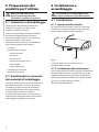
6 Installing and assembling
Only specialised personnel should be
allowed to install and assemble the device.
hh
6.1 Installation
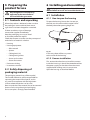
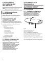
6.1.1 How to open the housing
To open the housing, loosen the 2 screws on
the side, turn the cover and the upper half of
the body about the opening hinge axis.
If there are obvious signs of damage,
contact the supplier immediately.
Keep the packaging in case you need
to send the product for repairs.
Check the contents to make sure they correspond
with the list of materials as below:
• Housing
• Housing equipment:
• Allen wrench
• Spacers
Fig. 01
• Cable glands (x3)
• Cable glands gaskets
In this way there will be easy access
to the inside of the housing.
• Screws and washers
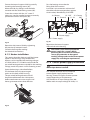
6.1.2 Camera installation
• Screws for camera
This section describes how to install the camera
inside the housing. It should be remembered that
the power supply can be taken from the circuit
supplied after making sure it is correct one.
• Desiccant salt bag
• Instructions manual
5.2 Safely disposing of
packaging material
The packaging material can all be recycled.
The installer technician will be responsible for
separating the material for disposal, and in
any case for compliance with the legislation
in force where the device is to be used.
Bear in mind that if the material has to be returned
due to a fault, using the original packaging
for its transport is strongly recommended.
4
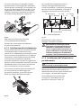
Open the housing as described before.
Pass the heating wire under the
fixing slide of the camera.
Move the slide, by sliding it until the holes
coincide with the slide locking screws (02).
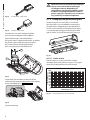
Insert the 2-pin connector at the end of
the cable into the correspondent support
circuit socket, identified by J3 HEATER.
Fasten the camera with the 1/4" screw. If
necessary, use the supplied spacers to correctly
position the camera and optics (03).
01
03
EN - English - Instructions manual
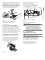
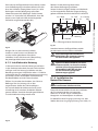
Extract the internal support slide by partially
loosening the fastening screws (01).
J2 - OUT J5 - Camera
J8 - Blower
OUT
J2 - Terminal
J1 - IN
02
J3 - Heater
J7 - Power supply
SW1 - Power supply
Fig. 02
Reposition the internal slide by tightening
the previously loosened screws.
Close the housing after making
the electrical connections.
6.1.3 Heater installation
This section describes how to install the heater
option in the housings not provided with.
Heaters can be supplied with working voltages
of 12Vdc/24Vac or 115/230Vac and include the
pre-wired heating element suitable for the working
voltage, metal dissipators and kit fastening screws.
Open the housing as described before.
Fix the heater kit to the prearranged
points on the body of the housing.
The pre-wired heating element should
be positioned between the 2 dissipators
before attachment to ensure contact and
hence guarantee correct heat diffusion.
Fig. 04
Reposition the internal support
slide and close the housing.
The circuit is also able to provide the
power supply for a camera. While
powering the circuit from an external
source, pay attention to the type of
working voltage and use the correct power
supply kit, according to requirements.
hh
6.1.4 Camera power supply installation
Not usable in housings with
wiper device installed.
hh
This chapter describes how to install the
camera power supply option into the
housing. There are 2 types of camera power
supply depending on requirements.
One model has an input voltage from 100240Vac with an output voltage of 12Vdc, 1A.
Fig. 03
5
When the circuit is powered by an external
source care must be taken to the type
of voltage used and, depending on
requirements, to the correct power supply
kit. When installing the optional camera
power supply it is not necessary to remove
any previously installed component.
Fig. 05
IN 100-240Vac - OUT 12Vdc.
6.1.5 Changing the germanium glass
Fig. 06
IN 230Vac - OUT 24Vac.
The other has an input voltage of 230Vac
and an output voltage of 24Vac, 400mA.
Germanium glass has two colours. Inside the
housing there is an anti-reflection coating that
changes colour (depending on the direction of
vision). On the outside, on the other hand, there
is a scratchproof coating to make the glass dark
grey in colour. To install the new glass see Fig. 9.
Open the housing as described before.
Using the screws supplied with the kit, assemble
the power supply with the support bracket
(01) and the corner attachment bracket
(02), using the points provided for this.
02
Fig. 09
01
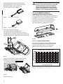
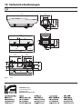
6.1.5.1 Limits to use
The housing has a front panel with a 50mm
diameter, 2mm thick germanium glass. The graph
shows the visible spectrum for the window.
Ge AR 2 sides - 2mm Thick
Wavelength (µm)
Fig. 10
Fig. 08
Close the housing.
6
Field of application from 7.5 to 14 µm.
14
13
12
9
10
11
8
7
6
5
4
3
5
Insert the 6-pin connector at the end of the
cable into the correspondent one on the support
circuit, identified by J7 (Fig. 04, page 5).
Transmittance (%)
Fig. 07
100
90
80
70
60
50
40
30
20
10
0
2,
EN - English - Instructions manual
hh
9 Technical specifications
7.1 Cleaning IR glass
and plastic parts
9.1 General
Surface dirt should be rinsed away with water and
then the window cleaned with a neutral soap diluted
with water, or specific products for spectacle lens
cleaning. These should be applied with a soft cloth.
Sunshield in ABS
When cleaning the window with the IR
filter, take extra care not to scratch or
damage the outer surface treated with
carbon coating. Damage to this coating
could also interfere with the transparency
of the surface to infrared light. Do not
use ethyl alcohol, solvents, hydrogenated
hydrocarbons, strong acids or alkalis.
These products will irreparably damage the
surface of the IR glass and the plastic parts.
hh
8 Disposal of waste
materials
This symbol mark and recycle system
are applied only to EU countries
and not applied to the countries
in the other area of the world.
nn
Your product is designed and manufactured
with high quality materials and components
which can be recycled and reused.
This symbol means that electrical and electronic
equipment, at their end-of-life, should be disposed
of separately from your household waste.
Please dispose of this equipment at your local
Community waste collection or Recycling centre.
In the European Union there are separate collection
systems for used electrical and electronic products.
EN - English - Instructions manual
7 Maintaining and cleaning
Aluminium
Epoxypolyester powder painting, RAL9002 colour
Stainless steel external screws
Supplied with instruction manual, desiccant bag,
accessories for camera and lens mounting
9.2 Mechanical
3xM16 cable glands
Germanium window glass
2mm (0.07in) thick, Ø 70mm (2.8in) external, Ø 50mm
(2.0in) internal
External non-scratch treatment (hard carbon coating)
Internal antireflection treatment
Spectral range from 7.5 to 14μm IR range
Average transmission from 7.5 to 11.5μm, 94%
Average transmission from 11.5 to 14μm, 90%
Internal usable area (WxH): 100x70mm (3.9x2.7in)
Internal usable length with and without accessories:
250mm (9.8in)
Unit Weight: HTV32K1 3kg / 6.6lb
9.3 Electrical
Heater Ton 15°C+/-3°C (59°F +/-37°F) Toff 22°C+/-3°C
(71°F +/-37°F)
-- IN 12Vdc/24Vac, consumption 20W max
-- IN 115/230Vac, consumption 40W max
Camera power supply
-- IN 100-240Vac - OUT 12Vdc, 50/60 Hz, 1A
-- IN 230Vac - OUT 24Vac, 50/60Hz, 400mA
9.4 Environment
Indoor / Outdoor
Operating temperature with heater: -20°C / +60°C (-4°F
/ +140°F)
Resistant to the salty fog until 1000 hours (according to
ISO9227)
9.5 Compliance to
CE according to EN61000-6-3, EN 60065, EN50130-4
IP66/IP67 according to EN 60529 with cable glands
IP66/IP67 according to EN 60529 with special gaskets
and bracket with internal cable channel
IP55 according to EN 60529 with bracket with internal
cable channel
7
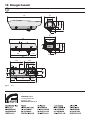
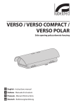
10 Technical drawings
The values are in millimeters.
jj
514
27
98
131
160
176
70
76
115
145
USABLE
AREA
13
14
70
A
88
163
140
100
412
A
260
76
117.5
400
22.5
212.5
70
40
187.5
112.5
60
87.5
Fig. 11
62
39
=
13
225
400
87.5
HTV
VIDEOTEC S.p.A.
www.videotec.com
Printed in Italy
MNVCHTV32_0919_EN
140
=
39
52.5
A-A
HTV
Custodia in alluminio per telecamere termiche
IT Italiano - Manuale di istruzioni
Sommario
ITALIANO
1 Informazioni sul presente manuale............................................................................. 3
IT - Italiano - Manuale di istruzioni
1.1 Convenzioni tipografiche..................................................................................................................................... 3
2 Note sul copyright e informazioni sui marchi commerciali....................................... 3
3 Norme di sicurezza........................................................................................................ 3
4 Identificazione............................................................................................................... 3
4.1 Descrizione e designazione del prodotto...................................................................................................... 3
4.2 Marcatura del prodotto......................................................................................................................................... 3
5 Preparazione del prodotto per l'utilizzo..................................................................... 4
5.1 Contenuto e disimballaggio................................................................................................................................ 4
5.2 Smaltimento in sicurezza dei materiali di imballaggio.............................................................................. 4
6 Installazione e assemblaggio....................................................................................... 4
6.1 Installazione.............................................................................................................................................................. 4
6.1.1 Apertura della custodia........................................................................................................................................................ 4
6.1.2 Installazione della telecamera............................................................................................................................................ 4
6.1.3 Installazione del riscaldamento......................................................................................................................................... 5
6.1.4 Installazione dell’alimentatore per telecamera............................................................................................................ 5
6.1.5 Installazione ricambio vetro al germanio....................................................................................................................... 6
6.1.5.1 Limiti di utilizzo............................................................................................................................................................................................. 6
7 Manutenzione e pulizia................................................................................................ 7
7.1 Pulizia del vetro IR e delle parti in plastica..................................................................................................... 7
8 Smaltimento dei rifiuti.................................................................................................. 7
9 Dati tecnici..................................................................................................................... 7
9.1 Generale..................................................................................................................................................................... 7
9.2 Meccanica.................................................................................................................................................................. 7
9.3 Elettrico....................................................................................................................................................................... 7
9.4 Ambiente.................................................................................................................................................................... 7
9.5 Conformità................................................................................................................................................................. 7
10 Disegni tecnici............................................................................................................. 8
2
1 Informazioni sul
presente manuale
1.1 Convenzioni tipografiche
PERICOLO!
Pericolosità elevata.
Rischio di scosse elettriche. Togliere
l'alimentazione prima di procedere con
le operazioni, salvo diversa indicazione.
gg
ATTENZIONE!
Pericolosità media.
L'operazione è molto importante per
il corretto funzionamento del sistema.
Si prega di leggere attentamente
la procedura indicata e di eseguirla
secondo le modalità previste.
hh
INFO
Descrizione delle caratteristiche del
sistema.
Si consiglia di leggere attentamente
per comprendere le fasi successive.
jj
2 Note sul copyright
e informazioni sui
marchi commerciali
I nomi di prodotto o di aziende citati sono
marchi commerciali o marchi commerciali
registrati appartenenti alle rispettive società.
3 Norme di sicurezza
Il produttore declina ogni responsabilità
per eventuali danni derivanti da un
uso improprio delle apparecchiature
menzionate in questo manuale. Si
riserva inoltre il diritto di modificarne il
contenuto senza preavviso. Ogni cura è
stata posta nella raccolta e nella verifica
della documentazione contenuta in
questo manuale, tuttavia il produttore
non può assumersi alcuna responsabilità
derivante dall'utilizzo della stessa.
Lo stesso dicasi per ogni persona o
società coinvolta nella creazione e
nella produzione di questo manuale.
hh
• Prima di effettuare interventi tecnici
sull'apparecchio togliere l'alimentazione elettrica.
• Non utilizzare cavi di alimentazione con
segni di usura o invecchiamento.
IT - Italiano - Manuale di istruzioni
Prima di installare e utilizzare questa unità, leggere
attentamente questo manuale. Conservare questo
manuale a portata di mano come riferimento futuro.
• L'installazione e la manutenzione del
dispositivo deve essere eseguita solo
da personale tecnico qualificato.
• Non effettuare per nessun motivo
alterazioni o collegamenti non previsti in
questo manuale: l'uso di apparecchi non
idonei può portare a gravi pericoli per la
sicurezza del personale e dell'impianto.
• Utilizzare solo parti di ricambio originali. Pezzi
di ricambio non originali potrebbero causare
incendi, scariche elettriche o altri pericoli.
• Prima di procedere con l'installazione controllare
che il materiale fornito corrisponda alle specifiche
richieste esaminando le etichette di marcatura
("4.2 Marcatura del prodotto", pagina 3).
4 Identificazione
4.1 Descrizione e
designazione del prodotto
La custodia stagna HTV, equipaggiata di vetro
al Germanio è stata progettata per installazioni
con telecamere termiche e offre una protezione
totale a tutte le condizioni ambientali.
La composizione del vetro al Germanio, con
le sue eccezionali caratteristiche, permette la
trasmissione da 7.5 fino a 14µm IR offrendo
un’ottima qualità ottica. Le dimensioni della
finestra consentono installazioni con telecamere
termiche con ottica di 9.2mm/45°.
L’apertura laterale facilita ampiamente
l’accessibilità alla telecamera, alle ottiche
ed a tutte le sue connessioni.
La sua tenuta stagna è mantenuta dalla guarnizione
in gomma neoprene e da 3 pressacavi.
Il corpo é in alluminio; il tettuccio
parasole in materiale ABS.
L’HTV offre diverse varianti di montaggio:
supporto a parete, supporto con
passaggio interno cavi e brandeggio.
Disponibile un’ampia gamma di accessori:
tettuccio, riscaldamento, alimentatore per
telecamera e contatto d’allarme antiapertura.
Gli accessori sono forniti come semplici kit di
montaggio per una facile installazione.
4.2 Marcatura del prodotto
Vedere l’etichetta posta sull’esterno dell’imballo.
3
5 Preparazione del
prodotto per l'utilizzo
Qualsiasi cambiamento non
espressamente approvato dal
costruttore fa decadere la garanzia.
IT - Italiano - Manuale di istruzioni
hh
5.1 Contenuto e disimballaggio
Alla consegna del prodotto verificare che
l'imballo sia integro e non abbia segni
evidenti di cadute o abrasioni.
In caso di evidenti segni di danno all'imballo
contattare immediatamente il fornitore.
6 Installazione e
assemblaggio
L'installazione e l'assemblaggio vanno
eseguiti solo da personale specializzato.
hh
6.1 Installazione
6.1.1 Apertura della custodia
Per l’apertura della custodia, svitare le 2 viti poste
sul fianco, far ruotare tettuccio e corpo superiore
attorno all’asse delle cerniere di apertura.
Conservare l'imballo nel caso sia necessario
inviare il prodotto in riparazione.
Controllare che il contenuto sia rispondente
alla lista del materiale sotto indicata:
• Custodia
• Dotazione per custodia:
• Chiave a brugola
• Distanziali
• Pressacavi (x3)
• Guarnizioni per pressacavi
• Viti e rondelle
• Viti per telecamera
• Sacchetto sali essiccanti
• Manuale di istruzioni
5.2 Smaltimento in sicurezza
dei materiali di imballaggio
I materiali d'imballo sono costituiti interamente
da materiale riciclabile. Sarà cura del tecnico
installatore smaltirli secondo le modalità di
raccolta differenziata o comunque secondo
le norme vigenti nel Paese di utilizzo.
Si ricorda comunque che in caso di ritorno di
materiale con malfunzionamenti è consigliato
l'imballaggio originale per il trasporto.
4
Fig. 01
In questo modo vi sarà un facile accesso
all’interno della custodia.
6.1.2 Installazione della telecamera
Questa sezione descrive come installare la telecamera
all’interno della custodia. Si ricorda che può essere
prelevata l’alimentazione dal circuito in dotazione
verificando preventivamente che sia quella corretta.
Aprire la custodia come da istruzioni
descritte precedentemente.
01
03
Passare il filo del riscaldamento sotto la
slitta per il fissaggio della telecamera.
Inserire il connettore a 2 poli posto all’estremità
del cavo nel suo corrispondente sul circuito di
appoggio, indicato con la scritta J3 HEATER.
J2 - OUT J5 - Camera
J8 - Ventilatore
OUT
J2 - Morsetto
J1 - IN
IT - Italiano - Manuale di istruzioni
Estrarre la slitta interna di appoggio svitando
parzialmente le viti di fissaggio (01). Muovere la
slitta facendola scorrere fino a far coincidere i fori
con le viti di bloccaggio della stessa (02). Fissare
la telecamera con la vite da 1/4". Se necessario
utilizzare i distanziali in dotazione per collocare
nel modo corretto telecamera e ottica (03).
02
J3 - Riscaldamento
J7 - Alimentatore
SW1 - Switch antiapertura
Fig. 02
Fig. 04
Riposizionare la slitta interna fissando
le viti precedentemente allentate.
Riposizionare la slitta interna di
appoggio e chiudere la custodia.
Chiudere la custodia dopo aver effettuato
le connessioni elettriche.
hh
6.1.3 Installazione del riscaldamento
Questa sezione descrive come installare l’opzione
riscaldamento nelle custodie che ne sono
sprovviste. Il riscaldamento può essere fornito con
tensioni di lavoro di 12Vdc/24Vac o 115/230Vac e
comprende, a seconda della tensione di utilizzo,
la resistenza di riscaldamento precablata, i
dissipatori metallici e le viti per il fissaggio del kit.
Nel circuito c’è anche la possibilità
di prelevare l’alimentazione per una
telecamera. Alimentando il circuito
da una sorgente esterna è necessario
prestare attenzione al tipo di tensione
utilizzata e adottare, a seconda delle
esigenze, il kit di alimentazione corretto.
6.1.4 Installazione dell’alimentatore
per telecamera
Aprire la custodia seguendo le indicazioni descritte
precedentemente. Fissare il kit di riscaldamento
nei punti predisposti sul corpo custodia.
hh
La resistenza precablata deve essere interposta
fra i 2 dissipatori prima del fissaggio per
garantirne il contatto e assicurare in questo
modo una corretta diffusione del calore.
Questa sezione descrive come installare l’opzione
alimentatore all’interno della custodia. Gli
alimentatori che possono essere installati sono
di 2 categorie a seconda delle esigenze.
Non utilizzabile nelle custodie
munite di sistema tergicristallo.
Un modello può avere una tensione
di ingresso da 100-240Vac con una
tensione in uscita pari a 12Vdc, 1A.
Fig. 03
5
Fig. 05
IN 100-240Vac - OUT 12Vdc.
Alimentando il circuito da una sorgente
esterna è necessario prestare attenzione
al tipo di tensione utilizzata e a seconda
delle esigenze, il kit di alimentazione
corretto. Per montare l’opzione
alimentatore non è necessario rimuovere
alcun componente preinstallato.
hh
6.1.5 Installazione ricambio
vetro al germanio
Il vetro al germanio presenta due colorazioni.
All’interno della custodia grazie ad uno strato
anti riflesso assume una colorazione variabile
(in funzione dell’orientamento). All’esterno è
presente invece uno strato anti-graffio il quale
conferisce una colorazione grigio scuro.
Fig. 06
IN 230Vac - OUT 24Vac.
Aprire la custodia seguendo le indicazioni
descritte precedentemente.
Utilizzando le viti fornite nel kit, montare
l’alimentatore con la staffa di appoggio
(01) e quella ad angolo di fissaggio (02), in
corrispondenza dei punti predisposti.
02
Fig. 09
6.1.5.1 Limiti di utilizzo
01
La custodia monta un frontale con una finestra in
germanio del diametro di 50mm spessa 2mm. Nel
grafico è riportato lo spettro visivo della finestra.
Ge AR 2 lati - Spessore 2mm
Lunghezza d’onda (µm)
Fig. 10
Fig. 08
Chiudere la custodia.
6
Campo di applicazione da 7.5 a 14 µm.
14
13
12
9
10
11
8
7
6
5
4
3
5
Inserire il connettore a 6 poli posto all’estremità
del cavo nel suo corrispondente, sul circuito di
appoggio, indicato con J7 (Fig. 04, pagina 5).
Trasmittanza (%)
Fig. 07
100
90
80
70
60
50
40
30
20
10
0
2,
IT - Italiano - Manuale di istruzioni
L’altra possibilità prevede un alimentatore di diverso
tipo che può avere una tensione di ingresso di
230Vac con tensione in uscita pari a 24Vac, 400mA.
7 Manutenzione e pulizia
9 Dati tecnici
7.1 Pulizia del vetro IR e
delle parti in plastica
9.1 Generale
Si consigliano saponi neutri diluiti con acqua o
prodotti specifici per la pulizia delle lenti degli
occhiali con l’utilizzo di un panno morbido.
Tettuccio in ABS
hh
8 Smaltimento dei rifiuti
Questo simbolo e il sistema di
riciclaggio sono validi solo nei paesi
dell'EU e non trovano applicazione
in altri paesi del mondo.
nn
Il vostro prodotto è stato costruito da
materiali e componenti di alta qualità,
che sono riutilizzabili o riciclabili.
Prodotti elettrici ed elettronici che portano
questo simbolo alla fine dell'uso devono essere
smaltiti separatamente dai rifiuti casalinghi.
Vi preghiamo di smaltire questo apparecchio
in un Centro di raccolta o in un'Ecostazione.
Nell'Unione Europea esistono sistemi di raccolta
differenziata per prodotti elettrici ed elettronici.
Verniciatura a polveri di epossipoliestere, colore RAL9002
Viteria esterna in acciaio Inox
Fornita con manuale di istruzioni, sacchetto sale,
accessori montaggio telecamera e obiettivo
9.2 Meccanica
3 pressacavi M16
Vetro al Germanio
Spessore 2mm, Ø 70mm esterno, Ø 50mm interno
Trattatamento esterno antigraffio (hard carbon coating)
Trattatamento interno antiriflesso
Range spettrale da 7.5 fino a 14μm
Media di trasmissione da 7.5 fino a 11.5μm, 94%
Media di trasmissione da 11.5 fino a 14μm, 90%
Dimensioni utili interne (WxH): 100x70mm
Lunghezza utile interna con e senza accessori: 250mm
9.3 Elettrico
Riscaldamento Ton 15°C+/-3°C Toff 22°C+/-3°C
-- IN 12Vdc/24Vac, consumo 20W max
-- IN 115/230Vac, consumo 40W max
Alimentatore per telecamera
-- IN 100-240Vac - OUT 12Vdc, 50/60 Hz, 1A
-- IN 230Vac - OUT 24Vac, 50/60Hz, 400mA
9.4 Ambiente
Interno / Esterno
Temperatura d’esercizio con riscaldamento: -20°C / +60°C
Resistente alle nebbie saline fino a 1000 ore (secondo
norma ISO9227)
9.5 Conformità
CE in accordo con EN61000-6-3, EN 60065, EN50130-4
IP66/IP67 in accordo con EN 60529 con pressacavi
IP66/IP67 in accordo con EN 60529 con passaggio
interno cavi con anelli di tenuta
IP55 in accordo con EN 60529 con passaggio interni cavi
Peso Unitario: HTV32K1 3kg
7
IT - Italiano - Manuale di istruzioni
Pulire la finestra con il filtro IR prestando
attenzione a non graffiare o rigare la
superficie esterna trattata con carbon
coating. Danneggiando tale rivestimento
c’è il rischio di compromettere la
trasparenza all’infrarosso della superficie.
Sono da evitare alcool etilico, solventi,
idrocarburi idrogenati, acidi forti e alcali.
L’utilizzo di detti prodotti danneggia
in modo irreparabile la superficie del
vetro IR e delle parti in plastica.
Alluminio
10 Disegni tecnici
I valori espressi sono in millimetri.
jj
514
27
98
131
160
176
70
76
88
AREA
UTILE
13
14
70
A
115
145
163
140
100
412
A
260
76
117.5
400
22.5
212.5
70
40
187.5
112.5
60
87.5
Fig. 11
62
39
=
13
225
400
87.5
HTV
VIDEOTEC S.p.A.
www.videotec.com
Printed in Italy
MNVCHTV32_0919_IT
140
=
39
52.5
A-A
HTV
Caisson en aluminium pour cameras thermiques
FR Français - Manuel d'instructions
Sommaire
FRANÇAIS
1 À propos de ce mode d’emploi..................................................................................... 3
FR - Francais - Manuel d'instructions
1.1 Conventions typographiques............................................................................................................................. 3
2 Notes sur le copyright et informations sur les marques de commerce..................... 3
3 Normes de securité........................................................................................................ 3
4 Identification................................................................................................................. 3
4.1 Description et désignation du produit............................................................................................................ 3
4.2 Marquage du produit............................................................................................................................................ 3
5 Préparation du produit en vue de l’utilisation............................................................ 4
5.1 Contenu et déballage............................................................................................................................................ 4
5.2 Élimination sans danger des matériaux d’emballage................................................................................ 4
6 Installation et assemblage............................................................................................ 4
6.1 Installation................................................................................................................................................................. 4
6.1.1 Ouverture du caisson............................................................................................................................................................. 4
6.1.2 Installation de la caméra...................................................................................................................................................... 4
6.1.3 Installation du chauffage..................................................................................................................................................... 5
6.1.4 Installation de l’alimentateur pour caméra................................................................................................................... 5
6.1.5 Installation vitre au germanium de remplacement.................................................................................................... 6
6.1.5.1 Limites d’utilisation..................................................................................................................................................................................... 6
7 Entretien et nettoyage.................................................................................................. 7
7.1 Nettoyage de la vitre IR et des parties en plastique................................................................................... 7
8 Élimination des déchets................................................................................................ 7
9 Données techniques...................................................................................................... 7
9.1 Généralités................................................................................................................................................................. 7
9.2 Mécanique................................................................................................................................................................. 7
9.3 Électrique................................................................................................................................................................... 7
9.4 Environnement........................................................................................................................................................ 7
9.5 En conformité avec ................................................................................................................................................ 7
10 Dessins techniques...................................................................................................... 8
2
1 À propos de ce
mode d’emploi
• L’installation et l’entretien du dispositif
doivent être exclusivement être effectués
par un personnel technique qualifié.
Avant d’installer et d’utiliser cet appareil,
veuillez lire attentivement ce mode d’emploi.
Conservez-le à portée de main pour pouvoir
vous y reporter en cas de besoin.
• Ne pas utiliser de câbles d’alimentation
usés ou endommagés.
DANGER!
Risque élevé.
Risque de choc électrique. Sauf indication
contraire, sectionner l’alimentation
avant de procéder à toute opération.
gg
ATTENTION!
Risque moyen.
Opération extrêmement importante
en vue d’un fonctionnement correct du
système; lire avec attention les opérations
indiquées et s’y conformer rigoureusement.
hh
REMARQUE
Description des caractéristiques du
système.
Il est conseillé de procéder à une
lecture attentive pour une meilleure
compréhension des phases suivantes.
jj
2 Notes sur le copyright
et informations sur les
marques de commerce
Les noms de produit ou de sociétés cités
sont des marques de commerce ou des
marques de commerce enregistrées.
3 Normes de securité
Le producteur décline toute responsabilité
pour les dommages éventuels dus à une
utilisation non appropriée des appareils
mentionnés dans ce manuel. On réserve
en outre le droit d’en modifier le contenu
sans préavis. La documentation contenue
dans ce manuel a été rassemblée et vérifiée
avec le plus grand soin, cependant, le
producteur ne peut pas s’assumer aucune
responsabilité dérivante de l’emploi de
celle là. La même chose vaut pour chaque
personne ou société impliquées dans la
création et la production de ce manuel.
hh
• Ne procéder sous aucun prétexte à des
modifications ou des connexions non prévues
dans ce manuel: l’utilisation d’appareils non
adéquats peut comporter des dangers graves
pour la sécurité du personnel et de l’installation.
FR - Francais - Manuel d'instructions
1.1 Conventions typographiques
• Sectionner l’alimentation électrique avant
toute intervention technique sur l’appareil.
• Utiliser uniquement des pièces de rechange
d’origine. Les pièces non d’origine peuvent être
source d’incendies, de choc électrique ou autres.
• Avant de procéder à l’installation, contrôler
que le matériel fourni correspond à la
commande et examiner les étiquettes de
marquage ("4.2 Marquage du produit", page 3).
4 Identification
4.1 Description et
désignation du produit
Le caisson HTV, équipé d’une vitre au Germanium,
est prévu pour protéger les caméras thermiques
des agressions climatiques extérieures.
Les caractéristiques exceptionnelles de la vitre
au Germanium, permettent la transmission de
7.5 à 14μm IR, en garantissant une excellente
qualité optique. Les dimensions de la fenêtre
permettent des installations avec caméras
thermiques avec optiques de 9.2mm/45°.
L’ouverture latérale facilite l’accès et la mise en place
de la caméra, des optiques et des raccordements.
Son étanchéité est obtenue grâce au joint
en néoprène et aux 3 presse-étoupes.
Le corps est en aluminium et le toit pare-soleil en ABS.
L’HTV permet différents type de montage:
support standard, support avec passage
interne des câbles ou sur tourelle.
Différents accessoires disponibles: toit paresoleil, chauffage, alimentation pour caméra
et contact d’alarme anti-ouverture.
Les accessoires sont livrés en kits de
montage pour une installation facile.
4.2 Marquage du produit
Voir l’étiquette sur l’extérieur de l’emballage.
3
5 Préparation du produit
en vue de l’utilisation
FR - Francais - Manuel d'instructions
Toute modification non approuvée
expressément par le fabricant entraînera
l’annulation de la garantie.
6 Installation et
assemblage
L’installation et l’assemblage
doivent exclusivement être effectués
par un personnel spécialisé.
hh
hh
5.1 Contenu et déballage
6.1 Installation
Lors de la livraison du produit, vérifier que
l’emballage est en bon état et l’absence de
tout signe évident de chute ou d’abrasion.
6.1.1 Ouverture du caisson
En cas de dommages évidents, contacter
immédiatement le fournisseur.
Pour l’ouverture du caisson, dévisser les 2 vis placées
sur le côté, faire tourner le toit pare-soleil et le corps
supérieur autour de l’axe des charnières d’ouverture.
Conserver l’emballage en cas de nécessité
d’expédition du produit pour réparation.
Contrôler que le contenu correspond à la
liste matériel indiquée ci-dessous:
• Caisson
• Dotation pour caisson:
• Clé Allen
• Entretoises
• Presse-étoupes (x3)
• Joint pour presse-étoupes
• Vis et rondelles
• Vis pour caméra
• Sachet sel déshydratant
• Manuel d'instructions
5.2 Élimination sans danger
des matériaux d’emballage
Le matériel d’emballage est entièrement composé
de matériaux recyclables. Le technicien chargé de
l’installation est tenu de l’éliminer conformément aux
dispositions en matière de collecte sélective et selon
les normes en vigueur dans le pays d’utilisation.
En cas de dysfonctionnement et de retour
de matériel , il est conseillé d’utiliser
l’emballage original pour le transport.
4
Fig. 01
On aura ainsi un accès facile à l’intérieur du caisson.
6.1.2 Installation de la caméra
Cette section décrit comment installer la
caméra à l’intérieur du caisson. Nous rappelons
qu’il est possible de prélever l’alimentation
à partir du circuit fourni, en vérifiant, au
préalable, que celle-ci soit correcte.
Ouvrez le caisson en suivant les
instructions précédentes.
Extraire la glissière interne d’appui en dévissant
partiellement les vis de fixation (01). Déplacer la
glissière en la faisant glisser jusqu’à ce que les trous
coïncident avec les vis de blocage de celle-ci (02).
Fixer la caméra avec la vis de 1/4". Si nécessaire,
utiliser les entretoises fournies pour placer de
façon correcte la caméra et l’optique (03).
03
Insérer le connecteur à 2 pôles placé en
bout de câble dans son emplacement sur le
circuit d’appui, indiqué par J3 HEATER.
J2 - OUT J5 - Camera
J8 - Ventilateur
OUT
J2 - Borne
J1 - IN
FR - Francais - Manuel d'instructions
01
Passer le fil du chauffage sous le chariot
pour la fixation de la caméra.
02
J3 - Chauffage
J7 - Alimentation
SW1 - Alarme anti-ouverture
Fig. 02
Fig. 04
Replacer la glissière interne en fixant
les vis précédemment desserrées.
Replacer la glissière d’appui interne
et fermer le caisson.
Fermez le caisson.
6.1.3 Installation du chauffage
hh
Cette section décrit comment installer l’option
chauffage dans les caissons qui n’en sont pas
équipés. Le chauffage peut être fourni avec des
tensions de travail de 12Vdc/24Vac ou 115/230Vac
et comprend, selon la tension d’utilisation, la
résistance de chauffage précâblée, les dissipateurs
métalliques et les vis pour la fixation du kit.
6.1.4 Installation de
l’alimentateur pour caméra
Dans le circuit, il est aussi possible de
prélever l’alimentation pour une caméra.
En alimentant le circuit à partir d’une
source externe, il faut faire attention au
type de tension utilisée et adopter, selon
les exigences, le kit d’alimentation correct.
Ouvrir le caisson selon les instructions décrites
précédemment. Fixer le kit de chauffage aux
points prédisposées sur le corps du caisson.
hh
La résistance précâblée doit être placée entre
les 2 dissipateurs avant la fixation pour en
garantir le contact et assurer de cette façon
une bonne diffusion de la chaleur.
Cette section décrit comment installer
l’option alimentateur à l’intérieur du caisson.
Les alimentateurs qui peuvent être installés
sont de 2 catégories selon les exigences.
Pas utilisable pour les caissons équipés
de système essuie-glace installé.
Un modèle peut avoir une tension
d’entrée allant de 100-240Vac avec une
tension en sortie égale à 12Vdc, 1A.
Fig. 03
5
En alimentant le circuit à partir d’une source
externe, il faut faire attention au type de
tension utilisée et, selon les exigences,
au bon kit d’alimentation. Pour monter
l’option alimentateur, il n’est nécessaire
d’enlever aucun composant déjà installé.
hh
6.1.5 Installation vitre au
germanium de remplacement
Fig. 05
IN 100-240Vac - OUT 12Vdc.
Fig. 06
IN 230Vac - OUT 24Vac.
La vitre au germanium présente deux colorations.
À l’intérieur du caisson, la coloration de la couche
antireflets varie en fonction de l’orientation.
La couche anti-éraflures externe présente une
coloration gris foncé. Pour installer la vitre
de remplacement, se reporter à la Fig. 9.
Ouvrir le caisson en suivant les
instructions décrites précédemment
En utilisant les vis fournies dans le kit, monter
l’alimentateur avec l’étrier d’appui (01) et l’étrier de
fixation à angle (02), en face des points prédisposés.
02
Fig. 09
6.1.5.1 Limites d’utilisation
01
Le caisson est équipé d’une partie frontale avec
fenêtre en germanium d’un diamètre de 50mm
et d’une épaisseur de 2mm. Le diagramme
représente le spectre visuel de la fenêtre.
Ge AR 2 côtés - Épaisseur 2mm
Longueur d’onde (µm)
Fig. 10
Fig. 08
Fermer le caisson.
6
Plage d’application de 7,5 à 14 µm.
14
13
12
9
10
11
8
7
6
5
4
3
5
Insérer le connecteur à 6 pôles placé en bout
de câble dans l’emplacement indiqué par
J7 sur le circuit d’appui (Fig. 04, page 5).
Transmittance (%)
Fig. 07
100
90
80
70
60
50
40
30
20
10
0
2,
FR - Francais - Manuel d'instructions
L’autre possibilité prévoit un alimentateur
de type différent qui peut avoir une tension
d’entrée de 230Vac avec une tension
en sortie égale à 24Vac, 400mA.
7 Entretien et nettoyage
9 Données techniques
7.1 Nettoyage de la vitre IR
et des parties en plastique
9.1 Généralités
Nous conseillons l’emploi, avec un chiffon
souple, de savons neutres dilués avec de
l’eau ou bien de produits spécifiques pour
le nettoyage des verres de lunettes.
Toit pare-soleil en ABS
hh
8 Élimination des déchets
Ce symbole et le système de recyclage
ne sont appliqués que dans les pays UE
et non dans les autres pays du monde.
nn
Votre produit est conçu et fabriqué avec des
matèriels et des composants de qualité supérieure
qui peuvent être recyclés et réutilisés.
Ce symbole signifie que les équipements électriques
et électroniques en fin de vie doivent être
éliminés séparément des ordures ménagères.
Nous vous prions donc de confier cet équipement
à votre Centre local de collecte ou Recyclage.
Dans l’Union Européenne, il existe des
systèmes sélectifs de collecte pour les produits
électriques et électroniques usagés.
Vernissage avec poudres époxypolyester, couleur
RAL9002
Visserie extérieure en acier inox
Livré avec manuel d’instructions, sachet déshydratant,
accessoires pour l’installation de la caméra et de l’objectif
9.2 Mécanique
3 presse-étoupes M16
Fenêtre avec vitre au Germanium
Epaisseur 2mm, Ø 70mm extérieur, Ø 50mm intérieur
Traitement extérieur anti-rayures (hard carbon coating)
Traitement intérieur anti-reftets
Réponse spectrale de 7.5 jusqu’à 14μm
Moyenne de transmission de 7.5 jusqu’à 11.5μm, 94%
Moyenne de transmission de 11.5 jusqu’à 14μm, 90%
Surface intérieure utile (WxH): 100x70mm
Longueur intérieur utile avec ou sans accessoires:
250mm
Poids Net: HTV32K1 3kg
9.3 Électrique
Chauffage Ton 15°C+/-3°C Toff 22°C+/-3°C
-- IN 12Vdc/24Vac, consommation 20W max
-- IN 115/230Vac, consommation 40W max
Alimentation pour caméra
-- IN 100-240Vac - OUT 12Vdc, 50/60 Hz, 1A
-- IN 230Vac - OUT 24Vac, 50/60Hz, 400mA
9.4 Environnement
Intérieur / Extérieur
Température d’exercice avec chauffage: -20°C / +60°C
Résistant aux brumes salines jusqu’à 1000 heures (selon
la norme ISO9227)
9.5 En conformité avec
CE selon EN61000-6-3, EN 60065, EN50130-4
IP66/IP67 selon EN 60529 avec presse-étoupes
IP66/IP67 selon EN 60529 avec support avec passage
interne des câbles et avec anneaux d’étanchéité
IP55 selon EN 60529 avec support avec passage interne
des câbles
7
FR - Francais - Manuel d'instructions
Nettoyer la fenêtre avec filtre IR en
ayant soin de ne pas rayer ni érafler
l’enduit protecteur de carbone externe.
L’endommagement du revêtement
risque de compromettre la transparence
à l’infrarouge de la surface. Éviter
toute utilisation d’alcool éthylique, de
solvants, d’hydrocarbures hydrogénés,
d’acides forts et d’alcalis. L’utilisation
de ce type de produit endommagera
irrémédiablement la surface de la
vitre IR et des parties en plastique.
Corps en aluminium
10 Dessins techniques
Les valeurs sont entendues en millimètres.
jj
514
27
98
131
160
176
70
76
115
145
SURFACE
UTILE
13
14
70
A
88
163
140
100
412
A
260
76
117.5
400
22.5
212.5
70
40
187.5
112.5
60
87.5
Fig. 11
62
39
=
13
225
400
87.5
HTV
VIDEOTEC S.p.A.
www.videotec.com
Printed in Italy
MNVCHTV32_0919_FR
140
=
39
52.5
A-A
HTV
Aluminiumgehäuse für Wärmebildkameras
DE Deutsch - Bedienungslanleitung
Inhaltsverzeichnis
DEUTSCH
1 Allgemeines................................................................................................................... 3
1.1 Schreibweisen.......................................................................................................................................................... 3
DE - Deutsch - Bedienungslanleitung
2 Anmerkungen zum Copyright und Informationen zu den Handelsmarken............. 3
3 Sichereitsnormen.......................................................................................................... 3
4 Identifizierung............................................................................................................... 3
4.1 Beschreibung und Bezeichnung des Produktes.......................................................................................... 3
4.2 Kennzeichnung des Produkts............................................................................................................................. 3
5 Vorbereitung des Produktes auf den Gebrauch......................................................... 4
5.1 Inhalt und Entfernen der Verpackung............................................................................................................. 4
5.2 Sichere Entsorgung der Verpackungsmaterialien....................................................................................... 4
6 Installation und Zusammenbau................................................................................... 4
6.1 Installation................................................................................................................................................................. 4
6.1.1 Öffnung des Schutzgehäuses............................................................................................................................................. 4
6.1.2 Installation der Kamera......................................................................................................................................................... 4
6.1.3 Installation der Heizung....................................................................................................................................................... 5
6.1.4 Installation des Netzteil für Kamera................................................................................................................................. 5
6.1.5 Einbau des Germanium-Austauschglases...................................................................................................................... 6
6.1.5.1 Anwendungsbereiche................................................................................................................................................................................ 6
7 Wartung und Reinigung................................................................................................ 7
7.1 Reinigung der IR-Scheibe und der Kunststoffteile...................................................................................... 7
8 Müllentsorgungsstellen................................................................................................ 7
9 Technische Daten........................................................................................................... 7
9.1 Allgemeines............................................................................................................................................................... 7
9.2 Mechanik.................................................................................................................................................................... 7
9.3 Elektrik......................................................................................................................................................................... 7
9.4 Umgebung................................................................................................................................................................ 7
9.5 Zertifizierungen....................................................................................................................................................... 7
10 Technische Zeichnungen............................................................................................ 8
2
1 Allgemeines
• Die Installation und Wartung der Vorrichtung
ist technischen Fachleuten vorbehalten.
Lesen Sie bitte vor dem Installieren und
dem Verwenden dieses Gerätes die
Bedienungsanleitung sorgfältig durch. Bewahren
Sie sie zum späteren Nachschlagen auf.
• Vor technischen Eingriffen am Gerät muss die
Stromversorgung unterbrochen werden.
1.1 Schreibweisen
ACHTUNG!
Mittlere Gefährdung.
Der genannte Vorgang hat große
Bedeutung für den einwandfreien
Betrieb des Systems: es wird
gebeten, sich die Verfahrensweise
anzulesen und zu befolgen.
hh
ANMERKUNG
Beschreibung der Systemmerkmale.
Eine sorgfältige Lektüre wird
empfohlen, um das Verständnis der
folgenden Phasen zu gewährleisten.
jj
2 Anmerkungen
zum Copyright und
Informationen zu den
Handelsmarken
Die angeführten Produkt- oder Firmennamen sind
Handelsmarken oder eingetragene Handelsmarken.
3 Sichereitsnormen
Der Hersteller lehnt jede Haftung für
eventuelle Schäden ab, die aufgrund
unsachgemäßer Anwendung der in diesem
Handbuch erwähnten Geräte entstanden
ist. Ferner behält er sich das Recht vor, den
Inhalt ohne Vorkündigung abzuändern.
Die Dokumentation in diesem Handbuch
wurde sorgfältig ausgeführt und überprüft,
dennoch kann der Hersteller keine Haftung
für die Verwendung übernehmen. Dasselbe
gilt für jede Person oder Gesellschaft, die
bei der Schaffung oder Produktion von
diesem Handbuch miteinbezogen ist.
hh
• Unter keinen Umständen dürfen Veränderungen
oder Anschlüsse vorgenommen werden, die
in diesem Handbuch nicht genannt sind: Der
Gebrauch ungeeigneten Geräts kann die Sicherheit
des Personals und der Anlage schwer gefährden.
• Es dürfen nur Original-Ersatzteile verwendet
werden. Nicht originale Ersatzteile können
zu Bränden, elektrischen Entladungen
oder anderen Gefahren führen.
• Vor der Installation ist anhand des
Kennzeichnungsschildes nachzuprüfen, ob das
gelieferte Material die gewünschten Eigenschaften
aufweist ("4.2 Kennzeichnung des Produkts", Seite 3).
4 Identifizierung
4.1 Beschreibung und
Bezeichnung des Produktes
Das dicht schließende Gehäuse HTV ist mit
Germaniumglas ausgestattet, das eigens für
Anlagen mit Wärmebildkameras ausgelegt ist.
Die Zusammensetzung des Germaniumglases mit
seinen außergewöhnlichen Eigenschaften ermöglicht
die Übertragung von IR-Strahlen von 7.5 bis 14μm
mit einer ausgezeichneten optischen Qualität. Wegen
der Fenstermaße lassen sich Installationen mit
Wärmebildkameras mit 9.2mm/45°- Optiken einbauen.
Die Seitenöffnung erleichtert erheblich den Zugriff auf
die Kamera, die Optiken und sämtliche Anschlüsse.
Seine Dichtheit wird durch die NeoprenDichtung und 3 Kabelschellen.
Der Körper ist aus Aluminium hergestellt und
das Sonnenschutzdach aus ABS- Kunstoff.
Das HTV bietet mehrere Montagevarianten:
Wandhalterung, Halterung mit innerer
Kabelführung und Schwenk-Neige-Kopf.
Erhältlich ist ein umfangreiches Zubehörprogramm
mit Sonnenschutzdach, Heizung, Kameranetzteil
und Alarmkontakt zum Schutz gegen Öffnung.
Die Zubehörartikel werden als einfach
zu installierender Bausatz geliefert.
4.2 Kennzeichnung des Produkts
Siehe das Schild außen auf der Verpackung.
3
DE - Deutsch - Bedienungslanleitung
GEFAHR!
Erhöhte Gefährdung.
Stromschlaggefahr; falls nichts anderes
angegeben, unterbrechen Sie die
Stromversorgung, bevor die beschriebenen
Arbeiten durchgeführt werden.
gg
• Es dürfen keine Versorgungskabel mit Verschleißoder Alterungsspuren verwendet werden.
5 Vorbereitung
des Produktes auf
den Gebrauch
Jede vom Hersteller nicht ausdrücklich
genehmigte Veränderung führt zum
Verfall der Gewährleistungsrechte.
DE - Deutsch - Bedienungslanleitung
hh
5.1 Inhalt und Entfernen
der Verpackung
Bei der Lieferung des Produktes ist zu prüfen, ob
die Verpackung intakt ist oder offensichtliche
Anzeichen von Stürzen oder Abrieb aufweist.
6 Installation und
Zusammenbau
Installation und Zusammenbau
sind Fachleuten vorbehalten.
hh
6.1 Installation
6.1.1 Öffnung des Schutzgehäuses
Zur Öffnung des Gehäuses die beiden an der
Flanke befindlichen Schrauben abdrehen,
nun die Haube und den oberen Korpus um
die Achse der Öffnungsscharniere drehen.
Bei offensichtlichen Schadensspuren
an der Verpackung muss umgehend
der Lieferant verständigt werden.
Bewahren Sie die Verpackung auf für den Fall, dass
das Produkt zur Reparatur eingesendet werden muss.
Prüfen Sie, ob der Inhalt mit der nachstehenden
Materialliste übereinstimmt:
• Gehäuse
• Lieferumfang für Gehäuses::
• Innensechskantschlüssel
Fig. 01
• Abstandsstücke
• Kabelschellen (x3)
Auf diese Weise gelangt man
leicht ans Gehäuseinnere.
• Dichtung für Kabelschelle
6.1.2 Installation der Kamera
• Schrauben und Scheiben
In diesem Abschnitt wird erläutert, wie die Kamera
in das Gehäuseinnere eingebaut wird. Denken
Sie daran, daß die Stromversorgung aus der
beiliegenden Schaltung bezogen werden kann, falls,
wie vorher zu prüfen ist, die Werte übereinstimmen.
• Schrauben für Kamera
• Bedienungslanleitungen
• Beutelchen mir Salz
5.2 Sichere Entsorgung der
Verpackungsmaterialien
Die Verpackungsmaterialien sind vollständig
wiederverwertbar. Es ist Sache des
Installationstechnikers, sie getrennt, auf jeden
Fall aber nach den geltenden Vorschriften
des Anwendungslandes zu entsorgen.
Es wird nochmals empfohlen, mit
Fehlfunktionen behaftetes Material in der
Originalverpackung zurückzusenden.
4
Das Schutzgehäuse wie frueher beschrieben öffnen.
Den internen Auflageschlitten herausziehen, indem
man die Befestigungsschrauben teilweise löst (01).
Reichen Sie den Heizungsdraht unter
dem Kamerabefestigungsschlitten.
Nun den Schlitten soweit gleiten lassen, bis seine
Bohrungen mit den Befestigungsschrauben
übereinstimmen (02). Befestigen Sie die Kamera
mit der 1/4"-Schraube. Falls erforderlich, kann die
Kamera samt Optik mit Hilfe der bei liegenden
Paßstücke ausgerichtet werden (03).
Setzen Sie den 2-poligen Stecker am Kabelende
an die vorgesehene Stelle der Trägerschaltung,
gekenn-zeichnet durch die Aufschrift J3 HEATER.
03
02
DE - Deutsch - Bedienungslanleitung
01
J2 - OUT J5 - Camera
J8 - Lüfter
OUT
J2 - Klemme
J1 - IN
J3 - Heizung
J7 - Netzteil
SW1 - Öffnungssicherer Alarmkontakt
Fig. 04
Fig. 02
Bringen Sie nun den internen Schlitten
wieder an seine Position und fixieren ihn
mit den vorher gelockerten Schrauben.
Schließen Sie das Gehäuse nach Überprüfung
der jeweilige elektrischen Anschlüsse.
6.1.3 Installation der Heizung
In diesem Abschnitt wird die Heizungsinstallation
in den Gehäuse behandelt, die noch nicht darüber
verfügen sind. Die Heizung ist lieferbar mit den
Betriebsspannungen 12Vdc/24Vac oder 115/230Vac
und enthält den zur jeweiligen Versorgungsspannung
passenden, bereits verkabelten Heizwiderstand,
die Metallableiter und die Fixierschrauben.
Öffnen Sie, wie oben beschrieben, das Gehäuse.
Befestigen Sie das Heizungs-Kit an den
vorgesehenen Stellen des Gehäusekörpers.
Der vorverkabelte Heizwiderstand muß, bevor
er befestigt wird, zwischen die beiden Ableiter
gesetzt werden, damit der Kontakt gewährleistet
ist und die Wärme richtig verteilt wird.
Jetzt den internen Auflageschlitten wieder
positionieren und das Gehäuse schließen.
Die Schaltung bietet daneben die
Möglichkeit, die Stromversorgung
für eine Kamera abzugreifen.
hh
Speist man den Schaltkreis aus einer
externen Quelle, ist darauf zu achten,
welcher Spannungstyp benutzt wird.
Verwenden Sie das Kit mit dem
für den Einzelfall geeigneten
Netzversorgungsgerät.
hh
6.1.4 Installation des
Netzteil für Kamera
Nicht anwendbar in Gehäusen mit
installiertem Scheibenwischer
hh
Dieser Abschnitt befaßt sich mit der Installation
des Zusatzspeisegerätes im Innern des
Gehäuses. Es lassen sich je nach Bedarf 2
Kategorien von Netzadaptern installieren.
Ein Modell hat eine Eingangsspannung von 100240Vac bei einer Ausgangsspannung von 12Vdc, 1A.
Fig. 03
5
Die Alternative ist ein anderer Typ des Netzteils
mit einer Eingangsspannung von 230Vac bei
einer Ausgangsspannung von 24Vac, 400mA.
IN 100-240Vac - OUT 12Vdc.
6.1.5 Einbau des GermaniumAustauschglases
Das Germaniumglas weist zwei Farbtöne auf.
Innerhalb des Gehäuses verändert sich wegen
einer reflexmindernden Schicht die Farbe mit der
Ausrichtung. Auf der Außenseite ist es wegen der
kratzfesten Schicht hingegen dunkelgrau. Für
den Einbau des Austauschglases siehe Fig. 9.
Fig. 06
IN 230Vac - OUT 24Vac.
Öffnen Sie das Gehäuse so, wie es
vorstehend beschrieben wird.
Mit den im Bausatz enthaltenen Schrauben
das Netzteil mit dem Tragbügel (01) und mit
dem Bügel mit Befestigungswinkel (02) an
den vorbereiteten Punkten montieren.
02
Fig. 09
6.1.5.1 Anwendungsbereiche
01
Im Frontteil des Gehäuses sitzt ein 2mm dickes
Germaniumfenster mit einem Durchmesser
von 50mm. In der Grafik ist das sichtbare
Spektrum des Fensters dargestellt.
Ge AR 2 Seiten - 2mm- Dicke
14
13
12
9
10
11
8
7
6
5
4
3
5
Setzen Sie den 6-spoligen Stecker am Kabelende
an die vorgesehene Stelle des Auflageschaltkreises,
gekennzeichnet durch die Aufschrift J7 (Fig. 04, Seite 5).
Transmission (%)
Fig. 07
100
90
80
70
60
50
40
30
20
10
0
2,
DE - Deutsch - Bedienungslanleitung
Fig. 05
Wenn der Schaltkreis von einer externen
Energiequelle gespeist wird, muß auf die
Versorgungsspannung geachtet werden.
Verwenden Sie das für den Einzelfall
geeignete Netzgerät. Für den Einbau des
Zusatzspeisers braucht keine vorinstallierte
Kom-ponente entfernt zu werden.
hh
Wellenlänge (µm)
Fig. 10
Fig. 08
Das Gehäuse schließen.
6
Der Anwendungsbereich liegt zwischen 7.5 und 14 µm.
7 Wartung und Reinigung
9 Technische Daten
7.1 Reinigung der IR-Scheibe
und der Kunststoffteile
9.1 Allgemeines
Es werden empfohlen verwässerte neutrale Seifen
oder spezifische Produkte zur Reinigung der
Brillenlinsen zusammen mit einem weichen Tuch.
Sonnenschutzdach aus ABS
hh
8 Müllentsorgungsstellen
Dieses Symbol und das entsprechende
Recycling-System gelten nur für
EULänder und finden in den anderen
Ländern der Welt keine Anwendung.
nn
Ihr Produkt wurde entworfen und hergestellt
mit qualitativ hochwertigen Materialien
und Komponenten, die recycelt und
wiederverwendet werden können.
Dieses Symbol bedeutet, daß elektrische und
elektronische Geräte am Ende ihrer Nutzungsdauer
von Hausmüll getrennt entsorgt werden sollen.
Bitte entsorgen Sie dieses Gerät bei Ihrer örtlichen
Sammelstelle oder im Recycling Centre.
In der Europäischen Union gibt es unterschiedliche
Sammelsysteme für Elektrik- und Elektronikgeräte.
Pulverlackierung mit Epoxydpolyester, Farbe RAL9002
Externe Schrauben aus rostfreiem Stahl
Im Lieferumfang enthalten Betriebsanleitungen,
Beutelchen mit Salz, Montagezubehör für Telekamera
und Objektiv
9.2 Mechanik
DE - Deutsch - Bedienungslanleitung
Bei der Reinigung des Fensters mit dem
IR-Filter ist darauf zu achten, dass die mit
Carbon Coating behandelte Oberfläche
nicht verkratzt oder gerillt wird. Wenn
diese Beschichtung Schaden nimmt,
besteht die Gefahr, dass die Durchlässigkeit
der Oberfläche für Infrarotstrahlen
beeinträchtigt wird. Zu vermeiden sind
Äthylalkohol, Lösungsmittel, hydrierte
Kohlenwasserstoffe, starke Säuren und
Alkalien. Durch diese Produkte wird die
Oberfläche der IR-Glasscheibe und der
Kunststoffteile irreparabel geschädigt.
Aluminium
3xM16-Kabelschellen
Fensterscheibe aus Germanium
2mm-Dicke, Ø 70mm Außenseite, Ø 50mm Innenseite
Kretzfeste Außenbehandlung (hard carbon coating)
Entspiegelte Innenbehandlung
Spektralbereich von 7.5 bis zu 14μm
Übertragungsmittel von 7.5 bis zu 11.5μm, 94%
Übertragungsmittel von 11.5 bis zu 14μm, 90%
Innere Nutzabmessungen (WxH): 100x70mm
Innere Nutzabmessungen mit oder ohne Zubehör:
250mm
Einheitsgewicht: HTV32K1 3kg
9.3 Elektrik
Heizung Ton 15°C+/-3°C Toff 22°C+/-3°C
-- IN 12Vdc/24Vac, Verbrauch 20W max
-- IN 115/230Vac, Verbrauch 40W max
Kameranetzteil
-- IN 100-240Vac - OUT 12Vdc, 50/60 Hz, 1A
-- IN 230Vac - OUT 24Vac, 50/60Hz, 400mA
9.4 Umgebung
Für innere / äußere Installationen
Betriebstemperatur mit Heizung: -20°C / +60°C
Salznebelbeständig bis zu 1000 Stunden (gemäß der
Norm ISO9227)
9.5 Zertifizierungen
CE gemäß EN61000-6-3, EN 60065, EN50130-4
IP66/IP67 gemäß EN 60529 mit Kabelschellen
IP66/IP67 gemäß EN 60529 mit innerer Kabelführung
und Dichtungsringen
IP55 gemäß EN 60529 mit innerer Kabelführung
7
10 Technische Zeichnungen
Maßangabe in Millimeter.
jj
514
27
98
131
160
176
70
76
115
145
NUTZFLÄCHE
13
14
70
A
88
163
140
100
412
A
260
76
117.5
400
22.5
212.5
70
40
187.5
112.5
60
87.5
Fig. 11
62
39
=
13
225
400
87.5
HTV
VIDEOTEC S.p.A.
www.videotec.com
Printed in Italy
MNVCHTV32_0919_DE
140
=
39
52.5
A-A
VIDEOTEC S.p.A.
www.videotec.com
Printed in Italy
MNVCHTV32_0919