1
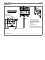
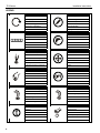
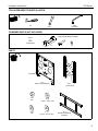
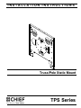
INSTALLATION INSTRUCTIONS
Truss/Pole Static Mount
TPS Series
TPS Series
Installation Instructions
DISCLAIMER
Milestone AV Technologies, and its affiliated corporations and
subsidiaries (collectively, "Milestone"), intend to make this
manual accurate and complete. However, Milestone makes no
claim that the information contained herein covers all details,
conditions or variations, nor does it provide for every possible
contingency in connection with the installation or use of this
product. The information contained in this document is subject
to change without notice or obligation of any kind. Milestone
makes no representation of warranty, expressed or implied,
regarding the information contained herein. Milestone assumes
no responsibility for accuracy, completeness or sufficiency of
the information contained in this document.
Chief® is a registered trademark of Milestone AV Technologies.
All rights reserved.
WARNING: Use this mounting system only for its intended
use as described in these instructions. Do not use
attachments not recommended by the manufacturer.
WARNING: Never operate this mounting system if it is
damaged. Return the mounting system to a service center
for examination and repair.
WARNING: Do not use this product outdoors.
IMPORTANT ! : The TPS mount is designed for
installation to a variety of pipe/truss dimensions and
can span a distance of up to 14" O.D.
--SAVE THESE INSTRUCTIONS-IMPORTANT SAFETY INSTRUCTIONS!
WARNING: A WARNING alerts you to the possibility of
serious injury or death if you do not follow the instructions.
CAUTION: A CAUTION alerts you to the possibility of
damage or destruction of equipment if you do not follow
the corresponding instructions.
WARNING: Failure to read, thoroughly understand, and
follow all instructions can result in serious personal injury,
damage to equipment, or voiding of factory warranty! It is
the installer’s responsibility to make sure all components
are properly assembled and installed using the instructions
provided.
WARNING: Failure to provide adequate structural strength
for this component can result in serious personal injury or
damage to equipment! It is the installer’s responsibility to
make sure the structure to which this component is attached
can support five times the combined weight of all equipment.
Reinforce the structure as required before installing the
component.
WARNING: Exceeding the weight capacity can result in
serious personal injury or damage to equipment! It is the
installer’s responsibility to make sure the combined weight of
all components attached to the TPS does not exceed 150 lbs
(68.04 kg).
•
2
The weight capacity of the TPS may be LIMITED to
the lowest weight capacity of any other component
or accessory used within the mounting system.
Installation Instructions
TPS Series
DIMENSIONS
TOP MOUNTING BUTTON ON
PSB-XXXX DRAWING GOES HERE
NOTE: CUSTOM INTERFACE BRACKET
NOT SHOWN. THE CUSTOM INTERFACE
BRACKET NEEDED FOR YOUR DISPLAY
WILL ADD BETWEEN 1/2” AND 2” IN DEPTH
AND MAY AFFECT LOCATION OF DISPLAY
ON THE MOUNT.
SEE PSB-XXXX DRAWING ALSO.
ATTACHES TO POLE/TRUSS USING
TPK SERIES CLAMPS (NOT INCLUDED)
APPROXIMATE CENTER OF DISPLAY
DIMENSIONS: INCHES
3
TPS Series
Installation Instructions
LEGEND
4
Tighten Fastener
Pencil Mark
Apretar elemento de fijación
Marcar con lápiz
Befestigungsteil festziehen
Stiftmarkierung
Apertar fixador
Marcar com lápis
Serrare il fissaggio
Segno a matita
Bevestiging vastdraaien
Potloodmerkteken
Serrez les fixations
Marquage au crayon
Measure
Drill Hole
Medir
Perforar
Messen
Bohrloch
Medir
Fazer furo
Misurare
Praticare un foro
Meten
Gat boren
Mesurer
Percez un trou
Phillips Screwdriver
Adjust
Destornillador Phillips
Ajustar
Kreuzschlitzschraubendreher
Einstellen
Chave de fendas Phillips
Ajustar
Cacciavite a stella
Regolare
Kruiskopschroevendraaier
Afstellen
Tournevis à pointe cruciforme
Ajuster
By Hand
Optional
A mano
Opcional
Von Hand
Optional
Com a mão
Opcional
A mano
Opzionale
Met de hand
Optie
À la main
En option
Hex-Head Wrench
Security Wrench
Llave de cabeza hexagonal
Llave de seguridad
Sechskantschlüssel
Sicherheitsschlüssel
Chave de cabeça sextavada
Chave de segurança
Chiave esagonale
Chiave di sicurezza
Zeskantsleutel
Veiligheidssleutel
Clé à tête hexagonale
Clé de sécurité
Hammer
Open-Ended Wrench
Martillo
Llave de boca
Hammer
Gabelschlüssel
Martelo
Chave de bocas
Martello
Chiave a punte aperte
Hamer
Steeksleutel
Marteau
Clé à fourche
Installation Instructions
TPS Series
TOOLS REQUIRED FOR INSTALLATION
#2
5/32"
(included)
9/16"
REQUIRED PARTS (NOT INCLUDED)
[TPK Truss/Pole Kit] (example)
TPK-4
or
TPK-5
Truss/Pole Kit
x4
x8
x8
PARTS
Faceplate
A (1)
[TPS mount assembly]
C (2)
3/8"
E (2)
3/8"
B (1)
[Truss plate]
D (2)
1.055" x .406 x .250"
F (1)
1.125" X .390" X .094"
G (1)
[Interface bracket kit]
(example)
5
TPS Series
Installation Instructions
INSTALLATION
NOTE: The orientation of the truss plate (B) when mounted on
a truss is the same as when mounted on a pole. The
number of clamps required will depend on the number
of trusses used for installation. (See Figure 3)
WARNING: Failure to provide adequate structural strength
for this component can result in serious personal injury or
damage to equipment! It is the installer’s responsibility to
make sure the structure to which this component is attached
can support five times the combined weight of all equipment.
Reinforce the structure as required before installing the
component.
Trusses used (2) (example)
x8
2
The TPS assembly is designed to accommodate vertical or
horizontal truss/pole mounting. For horizontal pole mounting,
proceed to Horizontal Installation section. To use the TPS in
the vertical configuration, proceed to Vertical Installation
section.
Vertical Installation
1.
Verify truss plate (B) is properly oriented for installation.
(See Figure 1)
NOTE:
(B)
1 Recessed, slotted flat
surface against pole
TPK clamps x 4
(not included)
Vertical
pole
(B)
Figure 3
Slot at 1
bottom
3.
Position faceplate (A) in front of truss plate ensuring the
mounting studs face the truss plate. (See Figure 4)
Side with mounting studs towards truss plate (B)
Figure 1
2.
Securely anchor truss plate (B) to pole using Chief TPK
clamp kit (not included) following instructions and using
hardware included in kit. (See Figure 2) and (See Figure 3)
To Display
3
(A)
2
x4
(B)
TPK clamp kit
(not included)
To
Trusses
or poles
(B)
Note: Trusses/poles
not shown for clarity.
Figure 2
6
Figure 4
Installation Instructions
TPS Series
4.
Align mounting studs on faceplate (A) with center upper
mounting hole and lower center slot in truss plate (B).
5.
Install two 1.055" x .406" x.250" Nylon spacers (D) onto
mounting studs on TPS faceplate (A). (See Figure 5)
6.
Place the two mounting studs on faceplate through center
upper mounting hole and lower center slot in truss plate (B).
7.
Secure top of TPS faceplate (A) to truss plate (B) using one
3/8" flat washer (E), and one 3/8" Stover lock nut (C). (See
Figure 5)
Horizontal Installation
1.
Rotate the truss plate (B) 90° and verify it is properly
oriented for horizontal mounting. (See Figure 6)
1
(A)
(B)
(B)
5 (D) x 2
Recessed, slotted flat surface
against pole
7
Lower center slot
Figure 6
4 Mounting Studs
(x 2)
(C) x 2
8
2.
Securely anchor truss plate (B) to horizontal pole using
Chief TPK accessory clamps (not included) following
instructions included with TPK clamp kit. (See Figure 7)
(F) x 1
(E) x 2
x4
2
Horizontal
Installation
Note: Trusses not shown for clarity.
Figure 5
8.
Secure bottom of TPS faceplate (A) to truss plate (B) using
one .094" washer (F), one 3/8" flat washer (E), and one
3/8" Stover lock nut (C). (See Figure 5)
9.
Proceed to Display Installation section.
(B)
TPK clamps (not provided)
Figure 7
7
TPS Series
Installation Instructions
3.
Secure top of faceplate (A) to the truss plate (B) using one
3/8" flat washer (E) and one 3/8" Stover lock nut (C). (See
Figure 8)
4.
Secure bottom of TPS faceplate (A) to the truss plate (B)
using one .094" washer (F), one 3/8" flat washer (E) and
one 3/8" Stover lock nut (C). (See Figure 8)
1.
Attach interface bracket (G) to display using the instructions
included with the interface bracket kit.
2.
Lift and maneuver display such that all mounting buttons fit
into mounting slots on TPS faceplate (A). (See Figure 10)
(A)
Horizontal
Installation
3
Mounting
slot
(C)
2
3
Mounting button
(E) x 2
(D) x 2
Figure 10
(F) x 1
4
3.
(C)
Lower display firmly into place. Ensure each button has fully
seated in its mounting slot. (See Figure 10) and (See
Figure 11)
Mounting slots (x4)
Display
Figure 8
3
DISPLAY INSTALLATION
WARNING: Exceeding the weight capacity can result
in serious personal injury or damage to equipment! It is
the installer’s responsibility to make sure the combined
weight of all components attached to the TPS does not
exceed 150 lbs (68.04 kg).
IMPORTANT ! : Make sure no power is supplied to the
display and the latching flag on the TPS is in the
unlocked position before attempting to attach the display.
(See Figure 9)
Locked
Unlocked
Figure 9
8
(A)
Note: Trusses not
shown for clarity.
Figure 11
Installation Instructions
4.
TPS Series
With the mounting buttons of the display fully engaged in
the slots of the TPS (A), secure display to the TPS by raising
the Q-Latch flag all the way up to the locked position. (See
Figure 12)
NOTE: If Q-Latch flag does not fully engage, ensure the
mounting buttons are fully seated in the lower part of
the mounting slots.
4 Locked
Adjustments
The TPS mount provides for limited roll adjustment to level the
display after installation.
To adjust display roll:
1.
Loosen the two roll adjustment nuts in upper and lower
center holes of truss plate. (See Figure 13)
2.
Level the display as desired.
3.
Tighten the two roll adjustment nuts. (See Figure 13)
Note: Mounting structure and hardware not shown for clarity.
Display
(A)
2 deg.
(B)
Mounting
buttons in
slots (4)
(A)
1
x2
3
x2
Figure 12
5.
Attach all cables to display.
View from back
Figure 13
9
TPS Series
Installation Instructions
(Optional) Security Lock
Removing the Display
WARNING: IMPROPER HANDLING CAN LEAD TO
DISPLAY FALLING CAUSING SERIOUS PERSONAL
INJURY OR DAMAGE TO EQUIPMENT! Inadequate support
of display while removing it may cause display to fall! Watch
for pinch points. Do not put your fingers between movable
parts.
IMPORTANT ! : Ensure Q-Latch flag securing display is
completely raised at all times except when removing or
installing display. The flag must be all the way up when
installing or removing cables.
1.
A hole is provided in the Q-Latch flag and TPS faceplate (A) to
accommodate the insertion of a padlock or similar locking
device.
1.
Insert padlock (not included) through lower (lined up) holes
of Q-Latch flag and TPS faceplate (A). (See Figure 15)
Q-Latch flag
1
With display securely supported, unlock display from TPS
(A) by lowering the Q-Latch flag all the way down to the
unlocked position. (See Figure 14)
(A)
1
Figure 15
Unlocked
(A)
(A)
Figure 14
2.
10
Using two people, slide display up and out of TPS (A).
Display
Installation Instructions
TPS Series
11
TPS Series
Installation Instructions
USA/International
Chief, a products division of
Milestone AV Technologies
8800-002567 Rev00
2014 Milestone AV Technologies
www.chiefmfg.com
04/14
Europe
Asia Pacific
A
P
F
A
P
F
A
6436 City West Parkway, Eden Prairie, MN 55344
800.582.6480 / 952.225.6000
877.894.6918 / 952.894.6918
Franklinstraat 14, 6003 DK Weert, Netherlands
+31 (0) 495 580 852
+31 (0) 495 580 845
Office No. 1 on 12/F, Shatin Galleria
18-24 Shan Mei Street
Fotan, Shatin, Hong Kong
P 852 2145 4099
F 852 2145 4477