1
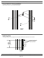
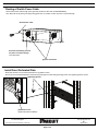
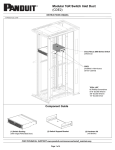
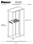
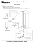
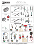
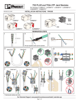
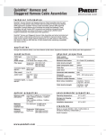
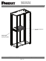
Switch Inlet Duct
(DIFBA3003S00S)
© Panduit Corp. 2014
INSTALLATION INSTRUCTIONS
V00029ES
Cisco Nexus 93128 Switch
(reference)
DIFBA3003S00S
(installed in Net-Access
S-Type Server Cabinet)
FOR TECHNICAL SUPPORT www.panduit.com/resources/install_maintain.asp
Page 1 of 4
V00029ES
INSTALLATION INSTRUCTIONS
Prepare Switch for Ducting Installation
-Remove bottom screws from front of switch rails and discard.
FRONT OF
CABINET
Install Cage Nuts
-Insert [4] Bonding cage nuts per equipment rail in rack space immediately above switch rails, at front of cabinet
[4] Bonding Cage Nuts
(install in Rack Space
above switch rails)
Intended
Mounting
Location
(3 rack spaces)
FRONT OF
CABINET
For Technical Support: www.panduit.com/resources/install_maintain.asp
Page 2 of 4
V00029ES
INSTALLATION INSTRUCTIONS
Install Switch Ducting
-Secure DIFBA3003S00S switch ducting to equipment rails with [8] new screws and the two bottom screws taken out earlier.
-Do not tighten [2] bottom screws --- Leave slightly extended for Front Perforated Plate installation (see page 4)
[8] Bonding Screws
FRONT OF
CABINET
[2] Bottom Screws
Provided in kit (with matching cage nuts if needed)
(leave slightly extended)
Adjust Switch Ducting
-Use [4] wing nuts and tooth washers to adjust position of switch duct seals
-Install foam seal (if necessary) to seal ducting to bottom of switch
[4] Wing Nuts and Tooth Washers
Install Foam Seal
(if necessary)
For Technical Support: www.panduit.com/resources/install_maintain.asp
Page 3 of 4
INSTALLATION INSTRUCTIONS
V00029ES
Routing of Switch Power Cable
-Route switch power cable through power grommet (located on either side of DIFBA3003S00S).
-Use utility knife to slit power grommet(s) along guide lines, as needed, to allow for power cord pass-through
Switch Power Cable
Slit Power Grommet(s) to allow
for power cord pass-through
(use utility knife)
[2] Power Grommets
Install Front Perforated Plate
-Slide slots at bottom of Front Perforated Plate over [2] bottom screws
-Secure top of Front Perforated Plate to switch ducting and equipment rails with [2] bonding screws, then tighten [2] bottom screws
[2] Bonding Screws.
[2] Bottom Screws
(tighten after plate installation)
For Instructions in Local Languages
and Technical Support:
www.panduit.com/resources/install_maintain.asp
www.panduit.com
Page 4 of 4
E-mail:
[email protected]
Fax:
(866)405-6654