1
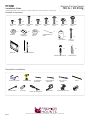
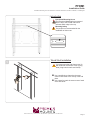
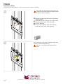
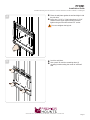
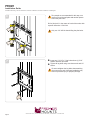
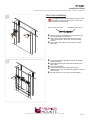
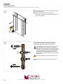
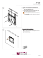
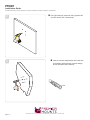
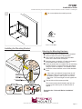
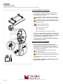
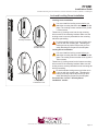
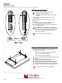
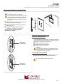
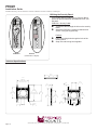
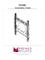
PFDM1
Installation Guide
Installationsanleitung, Guía de Instalacíon, Guida de Installazione, Guide d’Installation, Installatie gids
www.mounts.com | North America 800.368.9700 | International +1-714-632-7100
1321 S. State College Blvd., Fullerton, CA 92831 USA
PFDM1
Maximum Flat Panel Weight:
100 lb. / 45.35 kg.
Installation Guide
Installationsanleitung, Guía de Instalacíon, Guida de Installazione, Guide d’Installation, Installatie gids
Included components
x4
x4
x4
M4 x 12mm
screw
M4 x 16mm
screw
M4 x 25mm
screw
x4
x4
M6 x 12mm
screw
x4
Washers
M6 x 16mm
screw
M6 x 25mm
screw
x8
Universal 3
HoleWasher
Universal
Spacer
M8 x 25mm
screw
M8 x 16mm
screw
x1
Depth Measuring
Straw
x4
x1
Lock-it Barrel
x1
x4
x4
x4
x4
5/16” x 3”
Lag Bolts
x2
x4
Wall Plate
x4
Mounting Brackets
M6 Steel Stud Anchors
Finned Anchors
Required for installation
Protective Eyewear
Hand Held Drill
1/4” Drill Bit for
Wood Stud
7/16” Drill Bit for
Steel Stud
N
Socket Wrench
Page 2
1/2” Socket
Phillips Tip Screwdriver
3/8” Concrete
Drill Bit
Pencil
O
Tape Measure
Electronic Stud Finder
www.mounts.com | North America 800.368.9700 | International +1-714-632-7100
Level
PFDM1
Installation Guide
Installationsanleitung, Guía de Instalacíon, Guida de Installazione, Guide d’Installation, Installatie gids
Introduction
Directional Mounting Arrow
The Directional Mounting Arrow stamped
into the top of the PFDM1 wall mount
indicates which edge is the top.
Mounting Safety
Two people are recommended for the
installation of this mount.
Wood Stud Installation
1
You must secure the wall plate to two (2)
wall studs with a minimum of four (4) lag
bolts (2 lag bolts for each stud found).
X
X
Use a stud finder to determine the exact
nn
center of wall studs in the vicinity of the wall
plate.
Use a pencil to mark the exact center of each
oo
of the wall studs.
www.mounts.com | North America 800.368.9700 | International +1-714-632-7100
Page 3
PFDM1
Installation Guide
Installationsanleitung, Guía de Instalacíon, Guida de Installazione, Guide d’Installation, Installatie gids
2
Two people are recommended for this step; one
person to level the wall plate and another person
to mark the wall stud location.
Place the wall plate against the wall in the desired
nn
viewing location.
Adjust the wall plate to align the mount slots in the
oo
wall plate with the center of the wall studs.
Level the wall plate.
pp
Use a pencil to mark the upper right mounting
qq
location along the center of the wall stud.
3
Drill a “pilot hole” in the center of the upper right mark
using a 1/4” drill bit and power drill.
Only use a 1/4” drill bit when drilling the pilot
holes.
Page 4
www.mounts.com | North America 800.368.9700 | International +1-714-632-7100
PFDM1
Installation Guide
Installationsanleitung, Guía de Instalacíon, Guida de Installazione, Guide d’Installation, Installatie gids
4
Place the wall plate against the wall and align it with
nn
the pilot hole.
Insert one (1) 5/16” x 3″ lag bolt and one (1) 5/16”
oo
washer into the upper right mounting hole and
tighten using a socket wrench and 1/2” socket.
Do not overtighten the lag bolt.
5
Level the wall plate.
nn
Use a pencil to mark the remaining three (3)
oo
mounting locations along the center of each wall
stud.
www.mounts.com | North America 800.368.9700 | International +1-714-632-7100
Page 5
PFDM1
Installation Guide
Installationsanleitung, Guía de Instalacíon, Guida de Installazione, Guide d’Installation, Installatie gids
6
Two people are recommended for this step; one
person to level the wall plate and another person
to drill the pilot holes.
Drill a “pilot hole” in the center of each of the marks with
a power drill and a 1/4” drill bit.
Only use 1/4” drill bit when drilling the pilot holes.
7
Insert one (1) 5/16” x 3” lag bolt and one (1) 5/16”
nn
washer into each pilot hole.
Tighten all lag bolts using a socket wrench and 1/2”
oo
socket.
Do not overtighten the lag bolts when attaching
the mount to the wall. Improper installation may
result in personal injury or property damage.
Page 6
www.mounts.com | North America 800.368.9700 | International +1-714-632-7100
PFDM1
Installation Guide
Installationsanleitung, Guía de Instalacíon, Guida de Installazione, Guide d’Installation, Installatie gids
Steel Stud Installation
1
The supplied M6 steel stud anchors must be used
to install your mount to steel studs. Do not use
lag bolts or wood screws.
Steel Stud Anchor Screw
X
Steel Stud Anchor Sleeve
Identify the general location on the wall where you
nn
will be mounting your flat panel.
Use a stud finder to determine the exact center
oo
of each steel stud in the vicinity of the mounting
location.
Use a pencil and mark the exact center of each
pp
steel stud.
2
Place the wall plate against the wall in the desired
nn
viewing location.
Adjust the wall plate to match the locations of the
oo
steel studs.
Level the wall plate.
pp
Use a pencil and mark 2 upper and 2 lower
qq
locations where you will be drilling holes for the steel
stud anchors.
Set the wall plate to one side in a safe location.
rr
www.mounts.com | North America 800.368.9700 | International +1-714-632-7100
Page 7
PFDM1
Installation Guide
Installationsanleitung, Guía de Instalacíon, Guida de Installazione, Guide d’Installation, Installatie gids
3
Use a power drill and 7/16” drill bit to drill a hole at
nn
each of the marks.
Insert a steel stud anchor into each hole.
oo
If necessary, lightly tap each steel stud anchor into
place with a hammer.
4
Use a Phillips screwdriver to tighten each steel
stud anchor screw until the legs have completely
compressed against the back of the steel stud.
The steel stud anchor screw will feel tight when
you first begin to turn it until the legs begin to
compress. The steel stud anchor screw will then
turn easier for several turns. The steel stud anchor
screw will again feel tight when the legs have
completely compressed against the back of the
drywall. Stop turning the steel stud anchor screw
at that point.
Do not overtighten the steel stud anchor screw.
Remove the steel stud anchor screws and set them
aside.
Page 8
www.mounts.com | North America 800.368.9700 | International +1-714-632-7100
PFDM1
Installation Guide
Installationsanleitung, Guía de Instalacíon, Guida de Installazione, Guide d’Installation, Installatie gids
5
Align the wall plate over the steel stud anchor
nn
sleeves.
Insert a steel stud anchor screw and a washer into
oo
each steel stud anchor sleeve.
Use a Phillips screwdriver and tighten each steel
pp
stud anchor screw until it is just snug.
Do not overtighten the steel stud anchor screws.
Do not use a power drill to tighten the steel stud
anchor screws.
1
Concrete Wall Installation
Use a pencil and mark 4 mounting hole locations
nn
through the slots.
Level the wall plate
oo
www.mounts.com | North America 800.368.9700 | International +1-714-632-7100
Page 9
PFDM1
Installation Guide
Installationsanleitung, Guía de Instalacíon, Guida de Installazione, Guide d’Installation, Installatie gids
2
3
Drill 4 pilot holes of each mark using a power drill
nn
and 3/8˝ drill bit. Drill 3 inches deep.
Insert a concrete wedge anchor into each hole.
nn
If necessary, lightly tap each concrete wedge
anchor into place with a hammer.
X4
Finned Anchor
Page 10
www.mounts.com | North America 800.368.9700 | International +1-714-632-7100
PFDM1
Installation Guide
Installationsanleitung, Guía de Instalacíon, Guida de Installazione, Guide d’Installation, Installatie gids
4
Do not overtighten the mounting screws.
X4
5/16” Washer
X4
5/16” X 3” LAG BOLT
Installing the Mounting Bracket
Selecting the Mounting Hardware
Insert a small straw or toothpick into the threaded
nn
inserts found on the back of the flat panel.
Use a pencil to mark the depth of the threaded
oo
insert on the small straw or toothpick.
Mark the straw or toothpick 1/8” above the depth of
pp
the threaded insert, as shown in Figure 1.
Insert the small straw or toothpick into the remaining
qq
threaded inserts to compare and verify their depth
using the straw or toothpick’s 1/8” allowance mark.
Locate the correct diameter screw for the threaded
rr
insert.
Marking the 1/8”
Allowance
Small Straw or Toothpick
If the screw you selected is longer than the 1/8”
allowance mark on the small straw or toothpick,
as shown in Figure 2 and Figure 3, do not use
this screw. The screw length must not bypass the
mark.
Test each size of the screws provided.
ss
The correct screws should thread easily into the
mounting point and not pull out when tension is
applied.
Small Straw
or Toothpick
Depth Plus 1/8” Allowance
Mark
Small Straw
or Toothpick
Depth Plus 1/8” Allowance
Mark
Proceed to the “Universal Washer Installation”
section.
www.mounts.com | North America 800.368.9700 | International +1-714-632-7100
Page 11
PFDM1
Installation Guide
Installationsanleitung, Guía de Instalacíon, Guida de Installazione, Guide d’Installation, Installatie gids
Universal Washer Installation
Premier Mounts’ Universal Washers are designed to
accommodate the various M4, M5, M6 and M8 hole
sizes required by flat panels.
Do not place excessive pressure on the back of
the flat panel, as this may damage your flat panel.
The Universal Washer must be installed between
the head of the mounting screw and the mounting
bracket as shown.
Does your flat panel have:
●● Recessed mount points?
●● Uneven mount points?
●● A curved back?
●● Any obstruction near the mount point?
Mounting Screw
Universal Washer
If Yes, you must install Universal Spacers. Remove the
mounting brackets, Universal Washers, and mounting
screws from the back of the flat panel. Proceed to the
“Universal Spacer Installation” section.
Mounting Bracket
Flat Panel
If No, skip to the “Attaching the Mounting Bracket
to the Flat Panel” section.
Universal Spacer
Mount Point
Universal Spacer Installation
Premier Mounts’ Universal Spacers allow you to
attach the mounting bracket to flat panels which have
recessed or uneven mount points. Each Universal
Spacer adds ¼˝ to the distance between the mounting
bracket and your flat panel.
The Universal Spacers must be stacked and
oriented as shown.
The Universal Spacers must only be installed
between the mounting bracket and your flat panel.
The Universal Spacers will fit M4, M5, M6 and M8
screw sizes.
1˝
Page 12
¼˝
Proceed to the “Attaching the Mounting Bracket to
the Flat Panel” section.
www.mounts.com | North America 800.368.9700 | International +1-714-632-7100
PFDM1
Installation Guide
Installationsanleitung, Guía de Instalacíon, Guida de Installazione, Guide d’Installation, Installatie gids
Lock and Leveling Screw Installation
Leveling Screw Installation
You must install the leveling screws before you
attach the mounting bracket to the back of the flat
panel. The leveling screws consists of two (2) M6
x 75mm screws.
Thread one (1) leveling screw into the top mounting
hole on each of the mounting brackets. Make sure the
leveling screw is securely threaded into the mounting
tab before proceeding.
Leveling Screw
Correctly Threaded
Leveling Screw
Threaded Too Far
Do not thread the leveling screw any further once
it is even with the mounting tab. Threading the
leveling screw any further will prevent you from
safely attaching the flat panel to the wall plate.
Locking Screw Installation
You must install the locking screws before you
attach the mounting bracket to the back of the flat
panel. The locking screws consists of two (2) M6 x
75mm screws.
Thread one (1) locking screw into the bottom mounting
hole on each of the mounting brackets. Make sure the
locking screw is securely threaded into the mounting tab
before proceeding.
Do not thread the locking screw any further once
it is even with the mounting tab. Threading the
locking screw any further will prevent you from
safely attaching the flat panel to the wall plate.
Locking Screw
Correctly Threaded
Locking Screw
Threaded Too Far
Proceed to the “Lock-It™ Security Barrel
Installation” section.
www.mounts.com | North America 800.368.9700 | International +1-714-632-7100
Page 13
PFDM1
Installation Guide
Installationsanleitung, Guía de Instalacíon, Guida de Installazione, Guide d’Installation, Installatie gids
Ultilizing the Security Barrel
Optional security configurations include:
Mounting Tab
- PCB-CSL1 (sold separately)
- Padlock (Combination or Keyed; commercially
available)
Please read the following directions to install the
security barrel:
Remove the locking screw from the mounting
nn
bracket.
Place the locking screw into and through the
oo
security barrel (see illustration below).
Re-insert the locking screw and security barrel into
pp
the mounting bracket.
Do not thread the locking screw any further once
it is even with the mounting tab (see illustration to
the right). Threading the locking screw any further
will prevent you from safely attaching the flat
panel to the wall plate.
Do not overtighten the locking screw.
Locking Screw
Lock-It™ Security
Barrel
Attaching the Mounting Bracket to the Flat Panel
This section presumes that you have read and
understood these sections:
●● Selecting the Proper Mounting Hardware
●● Universal Washer Installation
●● Universal Spacer Installation
Place your flat panel screen-side down on a soft, flat
nn
surface.
Identify the number and location of the thread
oo
inserts on the back of your flat panel.
Aligning the holes on each mounting bracket with
pp
the thread inserts on the back of your flat panel.
Secure each mounting bracket to your flat panel by
qq
inserting a minimum of two (2) screws per bracket.
Do not overtighten the mounting hardware.
Page 14
www.mounts.com | North America 800.368.9700 | International +1-714-632-7100
PFDM1
Installation Guide
Installationsanleitung, Guía de Instalacíon, Guida de Installazione, Guide d’Installation, Installatie gids
Attaching the Flat Panel to the Wall Plate
This section requires two people.
Do not release your flat panel until you are
certain that top and bottom hooks of both
mounting brackets are securely seated on
the upper and lower mounting rails of the
wall panel.
Raise the flat panel past the top and bottom
nn
mounting rails on the wall panel.
Slide the flat panel down slowly, keeping it
oo
close to the wall.
Engage the top and bottom mounting
pp
brackets to the rails of the wall plate.
Proceed to the “Mounting Bracket
Adjustments” section.
Mounting Bracket Adjustments
Level Screw Adjustment
M6 x 75mm
Leveling Screw
(1 per Bracket)
If your flat panel is tilted too far to one side, the leveling
screws will allow you compensate for this tilt by simply
adjusting the screws with a screwdriver.
Loosen both locking screws.
nn
Adjust the tilt of your flat panel.
oo
Tighten both locking screws.
pp
Caution!
It is possible to dislodge your flat panel while you
level your flat panel. Use extreme caution until
you tighten the locking screws.
Locking Screw Adjustment
After you have finished leveling your flat panel, be sure
to tighten the two (2) M6 x 75mm locking screws.
Do not overtighten the locking screws.
M6 x 75mm
Locking Screw
(1 per Bracket)
www.mounts.com | North America 800.368.9700 | International +1-714-632-7100
Page 15
PFDM1
Installation Guide
Installationsanleitung, Guía de Instalacíon, Guida de Installazione, Guide d’Installation, Installatie gids
Ultilizing the Security Barrel
Your PFDM1 Mount includes one (1) Security Barrel
which can provide additional theft deterrence for your
flat panel.
PCB-CSL1 Security Cable Thread the cable through the hole on the security
nn
barrel.
Attach the PCB-CSL1 locking mechanism and
oo
secure it using the supplied key.
Padlock -
Place the locking hook through the hole of the
nn
security barrel.
Snap lock and locking hook together.
oo
PCB-CSL1
Padlock
(Combination or Keyed)
Technical Specifications
13.67
347.23
11.81
300
MIN VESA 200
MAX VESA 300
15.87
403.20
MIN VESA 200
MAX VESA 400
11.34
287.93
2.97
75.41
Page 16
.328
8.33
16.50
419.10
17.57
446.30
4.50
114.30
.433
11
.99
25.03
11.34
287.93
7.82
198.63
.406
10.31
www.mounts.com | North America 800.368.9700 | International +1-714-632-7100
4.50
114.30
8.69
220.73
PFDM1
Installation Guide
Installationsanleitung, Guía de Instalacíon, Guida de Installazione, Guide d’Installation, Installatie gids
PREMIER MOUNTS
LIMITED LIFETIME WARRANTY
What and Who is Covered by this Limited Lifetime Warranty
Premier Mounts warrants all mounting products to be free from defects in material and workmanship for the
lifetime of the original installation of the product.
What Premier Mounts Will Do
At the sole option of Premier Mounts, Premier Mounts will repair or replace any product or product part that is
defective. If Premier Mounts chooses to replace a defective product or part, a replacement product or part will
be shipped to you at no charge, but you must pay any related labor costs.
What is Not Covered: Limitations
Premier Mounts disclaims any liability for damage to mounts, adapters, displays, projectors, other property,
or personal injury resulting, in whole or in part, from improper installation, modification, use or misuse of its
products.
NOTWITHSTANDING ANYTHING TO THE CONTRARY IN THIS WARRANTY, THIS WARRANTY IS
LIMITED TO FIVE YEARS FROM THE DATE OF PURCHASE IN THE EVENT THAT THE WARRANTED PRODUCT IS COMMERCIALLY RENTED OUT.
Electrical products and components, such as amplifiers, speakers, motors, switches remote controls and related
electrical items, are backed by a 3-year warranty.
Premier Mounts disclaims all other warranties, express or implied, including warranties of merchantability and
fitness for a particular purpose. Premier Mounts is not responsible for incidental or consequential damages,
including but not limited to, inability to use its products or labor costs for removing and replacing defective
products or parts. Some states do not allow the exclusion or limitation of incidental or consequential damages,
so the above limitation or exclusion may not apply to you.
What Customers Must Do for Warranty Service
If you discover a problem that you think may be covered by the warranty, you must report it in writing to the
address below within thirty (30) days. Proof of purchase (an original sales receipt) from the original consumer
purchaser must accompany all warranty claims. Warranty claims must also include a description of the problem,
the purchaser’s name, address, and telephone number. General inquiries can be addressed to Premier Mounts
Customer Service at 1-800-368-9700. Warranty claims will not be accepted over the phone or by fax.
Premier Mounts
Attn: Warranty Claim
1321 S. State College Blvd.
Fullerton, CA 92831 USA
How State Law Applies
This warranty gives you specific legal rights, and you may also have other rights which vary from state to state.
Premier Mounts intends to make this manual accurate and complete. However, Premier Mounts makes no claim that
the information contained herein covers all details, conditions or variations, nor does it provide for every possible
contingency in connection with the installation or use of this product. The information contained in this document
is subject to change without notice or obligation of any kind. Premier Mounts makes no representation of warranty,
expressed or implied, regarding the information contained herein. Premier Mounts assumes no responsibility for
accuracy, completeness or sufficiency of the information contained in this document.
Warranty: http://www.mounts.com/warranty
Garantie, Garantía, Garanzia, Garantie, Waarborg
Page 17
www.mounts.com | North America 800.368.9700 | International +1-714-632-7100
9531-000-034-0X Rev.1