1
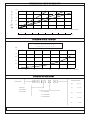
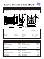
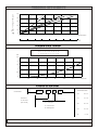
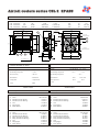
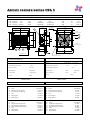
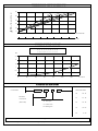
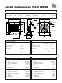
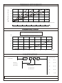
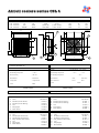
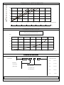
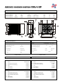
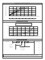
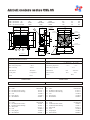
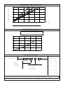
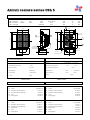
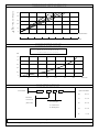
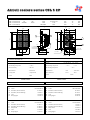
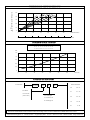
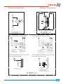
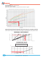
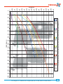
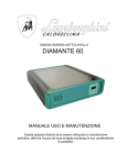
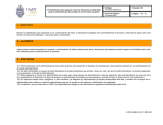
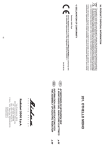
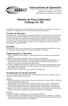
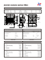
Air/oil coolers series CSL1
Code
CSL
CSL
CSL
CSL
Tension V
Frequency Hz
1.12.0.00
12
1.24.0.00
24
1.22.0.00
230
1.38.0.00 230/400
Rpm
DC
DC
50/60
50/60
3100
3100
2740/3120
2800/3150
=
03
146
Dia.Fan Weel.
0.100
0.100
0.050/0.061
0.053/0.056
K
297
=
146
Power kW
N° 8 HOLES
Ø 9 X 15
63
225
225
200
200
dB (A)
K mm.
67
67
68
68
145
145
170
170
282
25
25
247
45
30
3/4” BSP
02
A
140
290
245
200
04
330
B
06
01
05
30
45
1/2” BSP
15
100
280
15
310
48
N° 4 HOLES ø 12
130
3/4” BSP
FAN MOTORS TECHNICAL DATA
COOLER TECHNICAL DATA
Max working Pressure
:20 bar
Tension
Max working Temperature
: + 120° C
Max Working Temperature
Max oil Viscosity
: 100 CST
Min Working Temperature
Main Material
: Alluminium
Main Material
: Steel
: Fiber Glass
Cooling Fluid
: Compatible Al
Motor Protection
: IP 44
: IP 64
Colour
: Black
Colour
SPARE PARTS
Pos. Description
Cooler
Fan Motor(Air Flow Suction)
Fan Motor(Air Flow Blowing)
Cowl
Fixing Support
Shock Adsorbe
Code
Cooler
Fan Motor(Air Flow Suction)
Fan Motor(Air Flow Blowing)
Safety Guard
Cowl
Fixing Support
Shock Adsorber
: + 75° C
+ 75°C
: - 30° C
: Black
Pos. Description
Code
CSL 1.24.0.00
CSL1.00.0.00
10.70100 .1
10.70102 .1
15.65005 .0
15.65008 .0
20.80000 .1
01
02
02
04
05
06
CSL1.00.0.00
10.70002 .1
10.70004 .1
09.70050 .1
15.65005 .0
15.65008 .0
20.80000 .1
01
02
02
03
04
05
Cooler
Fan Motor(Air Flow Suction)
Fan Motor(Air Flow Blowing)
Safety Guard
Cowl
Fixing Support
06
Shock Adsorber
CSL 1.22.0.00
01
02
02
03
04
05
06
DC: 12/24V
SPARE PARTS
CSL 1.12.0.00
01
02
02
04
05
06
CA: DIN IEC38
Cooler
Fan Motor(Air Flow Suction)
Fan Motor(Air Flow Blowing)
Cowl
Fixing Support
Shock Adsorber
CSL1.00.0.00
10.70101 .1
10.70103 .1
15.65005 .0
15.65008 .0
20.80000 .1
CSL 1.38.0.00
CSL1.00.0.00
10.70001 .1
10.70003 .1
09.70050 .1
15.65005 .0
15.65008 .0
20.80000 .1
THERMIC EFFICIENCY
T°c= Temp.oil - Temp.air
50
in
n
min
i/m itri/mi
Litri/
L
60
40
itr
5L
40
100
min
Litri/
30
20
10
0
0
1
0
1
2
3
2
4
3
5
4
5
6
6
7X1000 Kcal/h
7
8 Kw
PRESSURE DROP
In order to know different viscosity , please multiply temp.oil x correction factor
CST 10 15 20 30 40 50 60 80 100
C 0,5 0,65 0,75 1,0 1,2 1,4 1,6 2,1 2,8
Bar
2,5
2
1,5
1
0,5
0
0
15
30
45
60
75
90
105 lt/min
CODIFICATION
Cooler series
CSL 1
12
A
Fan Motor
38
Thermostat series
38
38 - 27
47
47 - 36
60
60 - 49
70
70 - 59
TR
0 - 90
12-24-22-38
( See Code )
Air - Flow Type
A= Suction Fan
B= Blowing Fan
Technical characteristic herein mentioned are not binding and it can be modified from CIESSE without any notice.
CIESSE Srl P.zza Bergamo 12 - 24040 Ciserano - Zingonia (BG) ITALY - Tel: 035 - 884377 Fax:035 - 883227 E-MAIL: [email protected]
Ciesse s.r.l.
24040 CISERANO-ZINGONIA (BG) – Italy
Piazza Bergamo, 12
Tel. 035.884377-Fax 035.883227
www.ciesse-srl.it [email protected]
[email protected] [email protected]
MANUALE DI USO E MANUTENZIONE
SCAMB. CALORE CSL-CSA-CSB-D00000
USE AND MAINTENANCE HEAT
EXCHANGER CSL-CSA-CSB-D00000
INSTALLAZIONE
INSTALLATION
Gli scambiatori di calore aria/olio vengono normalmente
utilizzati per il raffreddamento di impianti oleodinamici
collegati sulla linea di scarico dove la pressione di
esercizio non supera i 20bar (massima ammessa per gli
scambiatori aria/olio).
Nel caso in cui la pressione di scarico superi i 20bar
(moltiplicazione di portata, viscosità olio), gli scambiatori
vengono inseriti nei Sistemi di Raffreddamento Autonomo
dotati di pompa di ricircolo e by-pass.
E’ consigliabile montare gli scambiatori su antivibranti ed
effettuare il collegamento di ingresso e uscita olio con tubi
flessibili.
Gli scambiatori dovranno essere installati in modo che
non vi siano ostacoli alla potata dell’aria: pertanto la
distanza posteriore e quella anteriore deve essere pari o
superiore al raggio della ventola montata (schema 2). Se
l’impianto oleodinamico è posto in ambienti dove la
temperatura dell’olio è soggetta ad elevata escursione
termica è consigliabile montare una valvola di by-pass in
considerazione che con basse temperature la viscosità
dell’olio aumenta sensibilmente provocando oltre a forti
perdite di carico anche, nella maggior parte dei casi, il
superamento della pressione massima ammessa (schema
1).
Air/oil heat exchanges are generally used for cooling
oleo dynamic equipments linked on the exhaust line
where the exercise pressure isn’t over 20 bar (max
pressure admitted for air/oil heat exchangers)
. If the exhaust pressure is over 20 bar (flow
multiplication, oil viscosity) the heat exchangers are
placed into independent cooling systems with
recirculation pump and by-pass.
It’ s advisable to mount the heat exchangers on antivibrations and to link inlets and outlets with flexible
tubing.
The heat exchangers must be installed in order that there
aren’t obstacles to the airflow: the anterior and posterior
distance has to be as much or superior to the radius of
the fan mounted (scheme 2). If the oleo dynamic
equipment is placed in environments where the oil
temperature is subject to high temperature range it’s
advisable to mount a by-pass valve since with low
temperatures oil viscosity rises considerably causing
high pressure drops that, in most cases, are bigger than
the max pressure allowed. (Scheme 1)
COLLEGAMENTO PARTE ELETTRICA
ELECTRIC PART LINKING
Assicurarsi che la tensione V, la frequenza Hz e il senso
di rotazione dell’elettroventola siano come indicato nella
targhetta posta in modo visibile sugli scambiatori.
Seguire attentamente quanto descritto nello schema
elettrico allegato. (schema n.3)
Please be sure that Tension V, frequency Hz and
rotation direction of the electric fan are as shown by the
plate mounted on the heat exchangers.
Follow accurately what’s written in the electric scheme
attached (Scheme 3).
MANUTENZIONE LATO ARIA
AIR SIDE MAINTENANCE
Scollegare elettricamente lo scambiatore; smontare il
convogliatore, l’elettroventola e l’eventuale termostato.
Tutte le impurità possono essere rimosse con un getto
d’acqua calda, prestando attenzione che la direzione dello
stesso sia parallela alle alette, per facilitare la fuoriuscita
dello sporco.
Disconnect electrically the heat exchanger; disassemble
the conveyor, electric fan and thermostat (if present).
All the impurities can be removed with a warm water jet
paying attention that its direction is parallel to the fins to
help with the discharge of the dirt.
MANUTENZIONE LATO OLIO
OIL SIDE MAINTENANCE
Scollegare idraulicamente lo scambiatore; flussarlo contro
corrente con sostanze sgrassanti non aggressive per
l'alluminio. L’intensità dello sporco determinerà la durata
di tale operazione che poterà variare dai 15 ai 30 minuti.
Nel caso non fosse sufficiente ripetere più volte
l’operazione.
Disconnect hydraulically he heat exchanger; flux against
the flow the heat exchanger with degreasing substances
not aggressive for aluminium. The intensity of the dirt
will determine the duration of this operation that usually
lasts from 15 to 30 minutes.
In case the desired cleaning isn’t achieved repeat the
operation as many times ad needed.
Ciesse s.r.l.
24040 CISERANO-ZINGONIA (BG) – Italy
Piazza Bergamo, 12
Tel. 035.884377-Fax 035.883227
www.ciesse-srl.it [email protected]
[email protected] [email protected]
½ FAN
½ FAN
B
M
A
SCHEMA n°1
SCHEMA n°2
COLLEGAMENTO ELETTRICO 400 AC TRIF
COLLEGAMENTO ELETTRICO 230 AC TRIF
400 AC THREEPHASE. ELECTRIC WIRING
230 AC THREEPHASE. ELECTRIC WIRING
RS T
M
RS T
M
V2
V2
U2
U2
W2
W2
U1
U1
V1
V1
W1
W1
YG
YG
R
R
T
T
T= TERMOSTATO / THERMOSTAT
U1= NERO / BLACK
U2= VERDE / GREEN
V1= BLU / BLUE
V2= BIANCO / WHITE
W1= MARRONE / BROWN
W2= GIALLO / YELLOW
YG= TERRA / GROUND
R= RELE’ / RELAY
T= TERMOSTATO / THERMOSTAT
U1= NERO / BLACK
U2= VERDE / GREEN
V1= BLU / BLUE
V2= BIANCO / WHITE
W1= MARRONE / BROWN
W2= GIALLO / YELLOW
YG= TERRA / GROUND
R= RELE’ / RELAY
COLLEGAMENTO ELETTRICO 12-24 DC
COLLEGAMENTO ELETTRICO 230 AC MON
12-24 DC. ELECTRIC WIRING
230 AC MON. ELECTRIC WIRING
_
M
+
M
_
+
U2
R
Z
U1
T
C
T
YG
12-24V DC
U1= NERO / BLACK
V1= BLU / BLUE
W1= MARRONE / BROWN
YG= TERRA / GROUND
T= TERMOSTATO / THERMOSTAT
R= RELE’ / RELAY
T= TERMOSTATO / THERMOSTAT
SCHEMA n°3
Air/oil coolers series CSL1 2PASS
CSL
CSL
CSL
CSL
Code
Tension V Frequency Hz
1.12.0.00 2
1.24.0.00 2
1.22.0.00 2
1.38.0.00 2
12
24
230
230/400
DC
DC
50/60
50/60
Rpm
Power kW
3100
3100
2740/3120
2800/3150
0.100
0.100
0.050/0.061
0.053/0.056
N° 8 HOLES
Ø 9 X 15
=
03
146
225
225
200
200
dB (A)
K mm.
67
67
68
68
145
145
170
170
282
K
297
=
146
Dia.Fan Weel.
63
25
25
247
45
30
3/4” BSP
04
140
290
02
A
325
245
200
3/4” BSP
B
06
01
05
30
45
1/2” BSP
15
100
280
15
310
48
N° 4 HOLES ø 12
130
FAN MOTORS TECHNICAL DATA
COOLER TECHNICAL DATA
Max working Pressure
:20 bar
Tension
Max working Temperature
: + 120° C
Max Working Temperature
Max oil Viscosity
: 100 CST
Min Working Temperature
Main Material
: Alluminium
Main Material
: Steel
: Fiber Glass
Cooling Fluid
: Compatible Al
Motor Protection
: IP 44
: IP 64
Colour
: Black
Colour
SPARE PARTS
Pos. Description
Cooler
Fan Motor(Air Flow Suction)
Fan Motor(Air Flow Blowing)
Cowl
Fixing Support
Shock Adsorbe
Code
Cooler
Fan Motor(Air Flow Suction)
Fan Motor(Air Flow Blowing)
Safety Guard
Cowl
Fixing Support
Shock Adsorber
: + 75° C
+ 75°C
: - 30° C
: Black
Pos. Description
Code
CSL 1.24.0.00 2
CSL1.00.0.00 2
10.70100 .1
10.70102 .1
15.65005 .0
15.65008 .0
20.80000 .1
01
02
02
04
05
06
CSL1.00.0.00 2
10.70002 .1
10.70004 .1
09.70050 .1
15.65005 .0
15.65008 .0
20.80000 .1
01
02
02
03
04
05
Cooler
Fan Motor(Air Flow Suction)
Fan Motor(Air Flow Blowing)
Safety Guard
Cowl
Fixing Support
06
Shock Adsorber
CSL 1.22.0.00 2
01
02
02
03
04
05
06
DC: 12/24V
SPARE PARTS
CSL 1.12.0.00 2
01
02
02
04
05
06
CA: DIN IEC38
Cooler
Fan Motor(Air Flow Suction)
Fan Motor(Air Flow Blowing)
Cowl
Fixing Support
Shock Adsorber
CSL1.00.0.00 2
10.70101 .1
10.70103 .1
15.65005 .0
15.65008 .0
20.80000 .1
CSL 1.38.0.00 2
CSL1.00.0.00 2
10.70001 .1
10.70003 .1
09.70050 .1
15.65005 .0
15.65008 .0
20.80000 .1
THERMIC EFFICIENCY
T°c= Temp.oil - Temp.air
50
itr
8L
40
i/m
in
Li
38
tri/m
in
in
itri/m
65 L
30
20
10
0
0
1
0
2
1
3
2
5
4
3
5
4
6
6
7X1000 Kcal/h
7
8 Kw
PRESSURE DROP
In order to know different viscosity , please multiply temp.oil x correction factor
CST 10 15 20 30 40 50 60 80 100
C 0,5 0,65 0,75 1,0 1,2 1,4 1,6 2,1 2,8
Bar
1,5
1,2
0,9
0,6
0,3
0
0
10
20
30
40
50
60
70 lt/min
CODIFICATION
Cooler series
CSL1 2P
12
A
Fan Motor
38
Thermostat series
38
38 - 27
47
47 - 36
60
60 - 49
70
70 - 59
TR
0 - 90
12-24-22-38
( See Code )
Air - Flow Type
A= Suction Fan
B= Blowing Fan
Technical characteristic herein mentioned are not binding and it can be modified from CIESSE without any notice.
CIESSE Srl P.zza Bergamo 12 - 24040 Ciserano - Zingonia (BG) ITALY - Tel: 035 - 884377 Fax:035 - 883227 E-MAIL: [email protected]
Air/oil coolers series CSL 2
Code
CSL
CSL
CSL
CSL
Tension V Frequency Hz
2.12.0.00
12
2.24.0.00
24
2.22.0.00
230
2.38.0.00 230/400
Rpm
DC
DC
50/60
50/60
3350
3350
2550/2750
2650/2900
=
03
174,5
Dia.Fan Well mm.
dB (A)
K mm.
255
255
250
250
67
67
68
68
155
155
155/170
155/170
0.125
0.125
0.115/0.155
0.110/0.160
K
354
=
174,5
Power kW
N° 8 HOLES
Ø 9 X 15
63
331
25
25
304
45
30
3/4” BSP
240
390
300
345
04
02
A
425
B
06
01
05
30
45
1/2” BSP
15
100
330
15
360
53
N° 4 HOLES ø 12
130
3/4” BSP
FAN MOTORS TECHNICAL DATA
COOLER TECHNICAL DATA
Max Working Pressure
: 20 bar
Tension
Max Working Temperature
: + 120° C
Max Working Temperature
Max oil Viscosity
: 100 CST
Min Working Temperature
Main Material
: Alluminium
Main Material
: Steel
: Fiber Glass
Cooling Fluid
: Compatbile Al
Motor protection
: IP 44
: IP 64
Colour
: Black
Colour
SPARE PARTS
Pos. Description
Cooler
Fan Motor(Air Flow Suction)
Fan Motor(Air Flow Blowing)
Cowl
Fixing Support
Shock Adsorber
Code
Cooler
Fan Motor(Air Flow Suction)
Fan Motor(Air Flow Blowing)
Safety Guard(Air Flow Suction)
Safety Guard(Air Flow Blowing)
Cowl
Fixing Support
Shock Adsorber
+ 75°C
: + 75° C
: - 30° C
: Black
Pos. Description
Code
CSL 2.24.0.00
CSL2.00.0.00
10.70104 .1
10.70106.1
15.65006.0
15.65008.0
20.80000 .1
01
02
02
04
05
06
Cooler
Fan Motor(Air Flow Suction)
Fan Motor(Air Flow Blowing)
Cowl
Fixing Support
Shock Adsorber
CSL2.00.0.00
10.70006.1
10.70008 .1
09.70051 .1
09.70072 .1
15.65006 .0
15.65008 .0
20.80000 .1
01
02
02
03
03
04
05
06
Cooler
Fan Motor(Air Flow Suction)
Fan Motor(Air Flow Blowing)
Safety Guard(Air Flow Suction)
Safety Guard(Air Flow Blowing)
Cowl
Fixing Support
Shock Adsorber
CSL 2.22.0.00
01
02
02
03
03
04
05
06
DC: 12/24V
SPARE PARTS
CSL 2.12.0.00
01
02
02
04
05
06
CA: DIN IEC38
CSL2.00.0.00
10.70105 .1
10.70107 .1
15.65006 .0
15.65008 .0
20.80000 .1
CSL 2.38.0.00
CSL2.00.0.00
10.70005.1
10.70007.1
09.70051.1
09.70072.1
15.65006.0
15.65008.0
20.80000 .1
THERMIC EFFICIENCY
T°c= Temp.oil - Temp.air
50
40
30
L
/m
itri
in
min
tri/
0 Li
120
9
in
itri/m
min
Litri/
L
70
30
20
10
0
0
2
0
2
4
6
4
8
6
10
8
10
12
12
14X1000 Kcal/h
14
16 Kw
PRESSURE DROP
In order to know different viscosity , please multiply temp.oil x correction factor
CST 10 15 20 30 40 50 60 80 100
C 0,5 0,65 0,75 1,0 1,2 1,4 1,6 2,1 2,8
Bar
2,5
2
1,5
1
0,5
0
0
20
40
60
80
100
120
140 lt/min
CODIFICATION
Cooler series
CSL 2
12
A
Fan Motor
38
Thermostat series
38
38 - 27
47
47 - 36
60
60 - 49
70
70 - 59
TR
0 - 90
12-24-22-38
( See Code )
Air - Flow Type
A= Suction Fan
B= Blowing Fan
Technical characteristic herein mentioned are not binding and it can be modified from CIESSE without any notice
CIESSE Srl P.zza Bergamo 12 - 24040 Ciserano - Zingonia (BG) ITALY - Tel: 035 - 884377 Fax:035 - 883227 E-MAIL: [email protected]
Air/oil coolers series CSL 2 2PASS
Code
CSL
CSL
CSL
CSL
Tension V
2.12.0.00 2
2.24.0.00 2
2.22.0.00 2
2.38.0.00 2
Frequency Hz
12
24
230
230/400
DC
DC
50/60
50/60
Rpm
Power Kw
Dia.Fan Well mm.
dB (A)
K mm.
3350
3350
2550/2750
2650/2900
0.125
0.125
0.115/0.155
0.110/0.160
255
255
250
250
67
67
68
68
155
155
155/170
155/170
K
354
=
=
174,5
03
174,5
N° 8 HOLES
Ø 9 X 15
63
331
25
25
304
45
30
3/4” BSP
04
240
390
300
345
3/4” BSP
02
A
425
B
06
01
05
30
45
1/2” BSP
15
100
330
15
360
53
N° 4 HOLES ø 12
130
FAN MOTORS TECHNICAL DATA
COOLER TECHNICAL DATA
Max Working Pressure
: 20 bar
Tension
Max Working Temperature
: + 120° C
Max Working Temperature
Max oil Viscosity
: 100 CST
Min Working Temperature
Main Material
: Alluminium
Main Material
: Steel
: Fiber Glass
Cooling Fluid
: Compatbile Al
Motor protection
: IP 44
: IP 64
Colour
: Black
Colour
SPARE PARTS
Pos. Description
Cooler
Fan Motor(Air Flow Suction)
Fan Motor(Air Flow Blowing)
Cowl
Fixing Support
Shock Adsorber
Code
Cooler
Fan Motor(Air Flow Suction)
Fan Motor(Air Flow Blowing)
Safety Guard(Air Flow Suction)
Safety Guard(Air Flow Blowing)
Cowl
Fixing Support
Shock Adsorber
+ 75°C
: + 75° C
: - 30° C
: Black
Pos. Description
Code
CSL 2.24.0.00 2
CSL2.00.0.00 2
10.70104 .1
10.70106.1
15.65006.0
15.65008.0
20.80000 .1
01
02
02
04
05
06
Cooler
Fan Motor(Air Flow Suction)
Fan Motor(Air Flow Blowing)
Cowl
Fixing Support
Shock Adsorber
CSL2.00.0.00 2
10.70006.1
10.70008 .1
09.70051 .1
09.70072 .1
15.65006 .0
15.65008 .0
20.80000 .1
01
02
02
03
03
04
05
06
Cooler
Fan Motor(Air Flow Suction)
Fan Motor(Air Flow Blowing)
Safety Guard(Air Flow Suction)
Safety Guard(Air Flow Blowing)
Cowl
Fixing Support
Shock Adsorber
CSL 2.22.0.00 2
01
02
02
03
03
04
05
06
DC: 12/24V
SPARE PARTS
CSL 2.12.0.00 2
01
02
02
04
05
06
CA: DIN IEC38
CSL2.00.0.00 2
10.70105 .1
10.70107 .1
15.65006 .0
15.65008 .0
20.80000 .1
CSL 2.38.0.00 2
CSL2.00.0.00 2
10.70005.1
10.70007.1
09.70051.1
09.70072.1
15.65006.0
15.65008.0
20.80000 .1
THERMIC EFFICIENCY
T°c= Temp.oil - Temp.air
50
40
30
10
L
/m
itri
min
itri/
in
L
30
in
itri/m
70 L
20
10
0
0
2
0
2
4
6
4
8
6
10
8
10
12
12
14X1000 Kcal/h
14
16 Kw
PRESSURE DROP
In order to know different viscosity , please multiply temp.oil x correction factor
CST 10 15 20 30 40 50 60 80 100
C 0,5 0,65 0,75 1,0 1,2 1,4 1,6 2,1 2,8
Bar
1,5
1,2
0,9
0,6
0,3
0
0
12
24
36
48
60
72
84 lt/min
CODIFICATION
Cooler series
CSL 2 2P
12
A
Fan Motor
38
Thermostat series
38
38 - 27
47
47 - 36
60
60 - 49
70
70 - 59
TR
0 - 90
12-24-22-38
( See Code )
Air - Flow Type
A= Suction Fan
B= Blowing Fan
Technical characteristic herein mentioned are not binding and it can be modified from CIESSE without any notice
CIESSE Srl P.zza Bergamo 12 - 24040 Ciserano - Zingonia (BG) ITALY - Tel: 035 - 884377 Fax:035 - 883227 E-MAIL: [email protected]
Air/oil coolers series CSL 3
Code
CSL
CSL
CSL
CSL
Tension V
Frequency Hz
3.12.0.00
12
3.24.0.00
24
3.22.0.00
230
3.38.0.00 230/400
Rpm
DC
DC
50/60
50/60
2300
2300
2650/2950
2650/2800
397
=
Power kW
03
195,5
dB (A)
K mm.
305
305
300
300
69
69
70
70
170
170
155/170
155/170
0.125
0.125
0.160/0.205
0.180/0.270
K
=
195,5
Dia.Fan Well mm.
N° 8 HOLES
Ø 9 X 15
63
380
25
25
341
45
30
1” BSP
290
440
395
350
04
02
A
475
B
06
01
05
30
45
1/2” BSP
15
100
380
15
410
53
N° 4 HOLES ø 12
130
1” BSP
FAN MOTORS TECHNICAL DATA
COOLER TECHNICAL
Max Working Pressure
:20 bar
Tension
Max Working Temperature
: + 120° C
Max Working Temperature
Max oil Viscosity
: 100 CST
Min Working Temperature
Main Material
: Alluminium
Main Material
: Steel
: Fiber Glass
Cooling Fluid
: Compatible Al
Motor Protection
: IP 44
: IP 64
Colour
: Black
Colour
SPARE PARTS
Pos. Description
Cooler
Fan Motor(Air Flow Suction)
Fan Motor(Air Flow Blowing)
04
05
06
Cowl
Fixing Support
Shock Adsorber
Code
Cowl
Fan Motor(Fan Motor Suction)
Fan Motor(Fan Motor Blowing)
Safety Guard(Fan Motor Suction)
Cowl
Fixing Support
Shock Adsorber
+ 75°C
: + 75° C
: - 30° C
: Black
Pos. Description
Code
CSL 3.24.0.00
15.65007.0
15.65008.0
20.80000 .1
01
02
02
04
05
06
CSL3.00.0.00
10.70010.1
10.70012.1
09.70052.1
15.65007.0
15.65008.0
20.80000 .1
01
02
02
03
04
05
06
CSL3.00.0.00
10.70108 .1
10.70110 .1
CSL 3.22.0.00
01
02
02
03
04
05
06
DC: 12/24V
SPARE PARTS
CSL 3.12.0.00
01
02
02
CA: DIN IEC38
Cooler
Fan Motor(Air Flow Suction)
Fan Motor(Air Flow Blowing)
Cowl
Fixing Support
Shock Adsorber
CSL3.00.0.00
10.70109 .1
10.70111 .1
15.65007 .0
15.65008 .0
20.80000 .1
CSL 3.38.0.00
Cooler
Fan Motor(Air Flow Suction)
Fan Motor(Air Flow Blowing)
Safety Guard(Air Flow Suction)
Cowl
Fixing Support
Shock Adsorber
CSL3.00.0.00
10.70009 .1
10.70011 .1
09.70052 .1
15.65007 .0
15.65008 .0
20.80000 .1
THERMIC EFFICIENCY
T°c= Temp.oil - Temp.air
50
in
t/m
l
40
40
70
in
lt/m
100
in
lt/m
130
in
lt/m
30
20
10
0
0
3
0
3
6
9
6
12
9
15
12
15
18
18
21X1000 Kcal/h
21
24 Kw
PRESSURE DROP
In order different viscosity , please multiply temp.x correction factor
CST 10 15 20 30 40 50 60 80 100
C 0,5 0,65 0,75 1,0 1,2 1,4 1,6 2,1 2,8
Bar
2,5
2
1,5
1
0,5
0
0
20
40
60
80
100
120
140 lt/min
CODIFICATION
Cooler series
CSL 3
12
A
Fan Motor
38
Thermostat series
38
38 - 27
47
47 - 36
60
60 - 49
70
70 - 59
TR
0 - 90
12-24-22-38
( See Code )
Air - Flow Type
A= Suction Fan
B= Blowing Fan
Technical characteristic herein mentioned are not binding and it can be modified from CIESSE without any notice
CIESSE Srl P.zza Bergamo 12 - 24040 Ciserano - Zingonia (BG) ITALY - Tel: 035 - 884377 Fax:035 - 883227 E-MAIL: [email protected]
Air/oil coolers series CSL 3 2PASS
Code
CSL
CSL
CSL
CSL
Tension V Frequency Hz
3.12.0.00 2
12
3.24.0.00 2
24
3.22.0.00 2
230
3.38.0.00 2 230/400
Rpm
DC
DC
50/60
50/60
2300
2300
2650/2950
2650/2800
397
=
Power kW
03
195,5
dB (A)
K mm.
305
305
300
300
69
69
70
70
170
170
155/170
155/170
0.125
0.125
0.160/0.205
0.180/0.270
K
=
195,5
Dia.Fan Well mm.
N° 8 HOLES
Ø 9 X 15
63
380
25
25
341
45
30
1” BSP
04
290
440
395
350
1” BSP
02
A
475
B
06
01
05
30
45
1/2” BSP
15
100
360
15
410
53
N° 4 HOLES ø 12
130
FAN MOTORS TECHNICAL DATA
COOLER TECHNICAL
Max Working Pressure
:20 bar
Tension
Max Working Temperature
: + 120° C
Max Working Temperature
Max oil Viscosity
: 100 CST
Min Working Temperature
Main Material
: Alluminium
Main Material
: Steel
: Fiber Glass
Cooling Fluid
: Compatible Al
Motor Protection
: IP 44
: IP 64
Colour
: Black
Colour
SPARE PARTS
Pos. Description
Cooler
Fan Motor(Air Flow Suction)
Fan Motor(Air Flow Blowing)
04
05
06
Cowl
Fixing Support
Shock Adsorber
Code
Cowl
Fan Motor(Fan Motor Suction)
Fan Motor(Fan Motor Blowing)
Safety Guard(Fan Motor Suction)
Cowl
Fixing Support
Shock Adsorber
+ 75°C
: + 75° C
: - 30° C
: Black
Pos. Description
Code
CSL 3.24.0.00 2
15.65007.0
15.65008.0
20.80000 .1
01
02
02
04
05
06
CSL3.00.0.00 2
10.70010.1
10.70012.1
09.70052.1
15.65007.0
15.65008.0
20.80000 .1
01
02
02
03
04
05
06
CSL3.00.0.00 2
10.70108 .1
10.70110 .1
CSL 3.22.0.00 2
01
02
02
03
04
05
06
DC: 12/24V
SPARE PARTS
CSL 3.12.0.00 2
01
02
02
CA: DIN IEC38
Cooler
Fan Motor(Air Flow Suction)
Fan Motor(Air Flow Blowing)
Cowl
Fixing Support
Shock Adsorber
CSL3.00.0.00 2
10.70109 .1
10.70111 .1
15.65007 .0
15.65008 .0
20.80000 .1
CSL 3.38.0.00 2
Cooler
Fan Motor(Air Flow Suction)
Fan Motor(Air Flow Blowing)
Safety Guard(Air Flow Suction)
Cowl
Fixing Support
Shock Adsorber
CSL3.00.0.00 2
10.70009 .1
10.70011 .1
09.70052 .1
15.65007 .0
15.65008 .0
20.80000 .1
THERMIC EFFICIENCY
T°c= Temp.oil - Temp.air
50
40
ri/m
30
12
in
Lit
22
i/m
Litr
37
in
62 L
/m
Litri
in
itri/m
itri/m
in
in
80 L
20
10
0
0
3
0
3
6
6
9
12
9
15
12
15
18
18
21X1000 Kcal/h
21
24 Kw
PRESSURE DROP
In order different viscosity , please multiply temp.x correction factor
CST 10 15 20 30 40 50 60 80 100
C 0,5 0,65 0,75 1,0 1,2 1,4 1,6 2,1 2,8
Bar
1,5
1,2
0,9
0,6
0,3
0
0
12
24
36
48
60
72
84 lt/min
CODIFICATION
Cooler series
CSL 3 2P
12
A
Fan Motor
38
Thermostat series
38
38 - 27
47
47 - 36
60
60 - 49
70
70 - 59
TR
0 - 90
12-24-22-38
( See Code )
Air - Flow Type
A= Suction Fan
B= Blowing Fan
Technical characteristic herein mentioned are not binding and it can be modified from CIESSE without any notice
CIESSE Srl P.zza Bergamo 12 - 24040 Ciserano - Zingonia (BG) ITALY - Tel: 035 - 884377 Fax:035 - 883227 E-MAIL: [email protected]
Air/oil coolers series CSL 4
Code
CSL
CSL
CSL
CSL
Tension V
Frequency Hz
Rpm
Power kW
12
24
230
230/400
DC
DC
50/60
50/60
2300
2300
1450/1700
1450/1690
0,125
0,125
0.160 / 0.204
0.135 / 0.185
4.12.0.00
4.24.0.00
4.22.0.00
4.38.0.00
K mm.
185
185
243
243
67
67
73
72
385
385
400
400
THERMOSTAT
524
37
Dia.Fan Well mm. dB (A)
03
K
450
37
47
450
==
63
04
17,5
400
520
= =
450
02
12,5
17,5
01
05
15
25
60
475
500
N° 2 ø 1-1/4” GAS
60
25
12,5
Ø 1/2” GAS
47
15
100
15
15
485
515
130
FAN MOTORS TECHNICAL DATA
COOLER TECHNICAL
Max Working Pressure
:20 bar
Tension
Max Working Temperature
: + 120° C
Max Working Temperature
Max oil Viscosity
: 100 CST
Min Working Temperature
Main Material
: Alluminium
Main Material
: Steel
: Fiber Glass
Cooling Fluid
: Compatible Al
Motor Protection
: IP 44
: IP 64
Colour
: Black
Colour
SPARE PARTS
Pos. Description
Cooler
Fan Motor(Air Flow Suction)
Fan Motor(Air Flow Blowing)
Cowl
Fixing Support
Shock Adsorber
Code
Cowl
Fan Motor(Fan Motor Suction)
Fan Motor(Fan Motor Blowing)
Safety Guard(Fan Motor Suction)
Cowl
Fixing Support
Shock Adsorber
DC: 12/24V
+ 75°C
: + 75° C
: - 30° C
: Black
Pos. Description
Code
CSL 4.24.0.00
CSL4.00.0.00
10.70429 .1
10.70430 .1
15.65031.0
15.65008.0
20.80000 .1
01
02
02
Cooler
Fan Motor(Air Flow Suction)
Fan Motor(Air Flow Blowing)
04
05
06
Cowl
Fixing Support
Shock Adsorber
CSL4.00.0.00
10.70042.1
10.70043.1
09.70073.1
15.65571.0
15.65008.0
20.80000 .1
01
02
02
03
04
05
06
CSL 4.22.0.00
01
02
02
03
04
05
06
CA: DIN IEC38
SPARE PARTS
CSL 4.12.0.00
01
02
02
04
05
06
06
CSL4.00.0.00
10.70426 .1
10.70431 .1
15.65031 .0
15.65008 .0
20.80000 .1
CSL 4.38.0.00
Cooler
Fan Motor(Air Flow Suction)
Fan Motor(Air Flow Blowing)
Safety Guard(Fan Motor Suction)
Cowl
Fixing Support
Shock Adsorber
CSL4.00.0.00
10.70015 .1
10.70016 .1
09.70073.1
15.65571 .0
15.65008 .0
20.80000 .1
T°c=Temp.olio - Temp.aria
THERMIC EFFICIENCY
50
40
40
in
t/m
l
70
in
lt/m
t/m
l
00
in
1
0
14
lt/m
in
30
20
10
0
0
0
5
10
5
15
10
20
15
20
25
25
30
30
35X1000 Kcal/h
35
40 kW
PRESSURE DROP
In order different viscosity , please multiply temp.x correction factor
CST 10 15 20 30 40 50 60 80 100
C 0,5 0,65 0,75 1,0 1,2 1,4 1,6 2,1 2,8
Bar
1,5
1,2
0,9
0,6
0,3
0
0
25
50
75
100
125
150
175 lt/min
CODIFICATION
Cooler series
CSL 4
12
A
Fan Motor
38
Thermostat series
38
38 - 27
47
47 - 36
60
60 - 49
70
70 - 59
TR
0 - 90
12-24-22-38
( See Code )
Air - Flow Type
A= Suction Fan
B= Blowing Fan
Technical characteristic herein mentioned are not binding and it can be modified from CIESSE without any notice
CIESSE Srl P.zza Bergamo 12 - 24040 Ciserano - Zingonia (BG) ITALY - Tel: 035 - 884377 Fax:035 - 883227 E-MAIL: [email protected]
Air/oil coolers series CSL 4 2P
Code
Tension V
CSL 4.12.0.00 2P
CSL 4.24.0.00 2P
CSL 4.22.0.00 2P
CSL 4.38.0.00 2P
12
24
230
230/400
Frequency Hz
Rpm
DC
DC
50/60
50/60
Dia.Fan Well mm. dB (A)
Power kW
0.125
0.125
0.160 + 0.204
0.135 + 0.185
2300
2300
1450/1700
1450/1690
385
385
400
400
K mm.
185
185
243
243
67
67
73
72
THERMOSTAT
03
243
63
47
450
==
100
60
25
12,5
Ø 1/2” GAS
40
520
= =
450
12,5
02
05
01
15
25
60
475
500
N° 2 ø 1-1/4” GAS
04
15
125
15
15
485
515
155
06
FAN MOTORS TECHNICAL DATA
COOLER TECHNICAL
Max Working Pressure
:20 bar
Tension
Max Working Temperature
: + 120° C
Max Working Temperature
Max oil Viscosity
: 100 CST
Min Working Temperature
Main Material
: Alluminium
Main Material
: Steel
: Fiber Glass
Cooling Fluid
: Compatible Al
Motor Protection
: IP 44
: IP 64
Colour
: Black
Colour
SPARE PARTS
Pos. Description
Cooler
Fan Motor(Air Flow Suction)
Fan Motor(Air Flow Blowing)
Cowl
Fixing Support
Shock Adsorber
Code
Cowl
Fan Motor(Fan Motor Suction)
Fan Motor(Fan Motor Blowing)
Safety Guard(Fan Motor Suction)
Cowl
Fixing Support
Shock Adsorber
+ 75°C
: + 75° C
: - 30° C
: Black
Pos. Description
Code
CSL 4.24.0.00 2P
CSL4.00.0.00 2P
10.70429 .1
10.70430 .1
15.65031.0
15.65008.0
20.80000 .1
01
02
02
Cooler
Fan Motor(Air Flow Suction)
Fan Motor(Air Flow Blowing)
04
05
06
Cowl
Fixing Support
Shock Adsorber
CSL4.00.0.00 2P
10.70042.1
10.70043.1
09.70073.1
15.65571.0
15.65008.0
20.80000 .1
01
02
02
03
04
05
06
CSL 4.22.0.00 2P
01
02
02
03
04
05
06
DC: 12/24V
SPARE PARTS
CSL 4.12.0.00 2P
01
02
02
04
05
06
CA: DIN IEC38
CSL4.00.0.00 2P
10.70426 .1
10.70431 .1
15.65031 .0
15.65008 .0
20.80000 .1
CSL 4.38.0.00 2P
Cooler
Fan Motor(Air Flow Suction)
Fan Motor(Air Flow Blowing)
Safety Guard(Fan Motor Suction)
Cowl
Fixing Support
Shock Adsorber
CSL4.00.0.00 2P
10.70015 .1
10.70016 .1
09.70073.1
15.65571 .0
15.65008 .0
20.80000 .1
50
25
lt/m
in
40
in
lt/m
n
in
in
mi
lt/m
t/m 60 lt/
90
l
40
10
T°c= Temp.olio - Temp.aria
THERMIC EFFICIENCY
30
20
10
0
0
5
0
5
10
10
15
20
15
25
20
25
30
30
35X1000 Kcal/h
35
40 Kw
PRESSURE DROP
In order different viscosity , please multiply temp.x correction factor
CST 10 15 20 30 40 50 60 80 100
C 0,5 0,65 0,75 1,0 1,2 1,4 1,6 2,1 2,8
Bar
1,5
1,2
0,9
0,6
0,3
0
0
15
30
45
60
75
90
105 lt/min
CODIFICATION
Cooler series
CSL 4 2P
12
A
Fan Motor
38
Thermostat series
38
38 - 27
47
47 - 36
60
60 - 49
70
70 - 59
TR
0 - 90
12-24-22-38
( See Code )
Air - Flow Type
A= Suction Fan
B= Blowing Fan
Technical characteristic herein mentioned are not binding and it can be modified from CIESSE without any notice
CIESSE Srl P.zza Bergamo 12 - 24040 Ciserano - Zingonia (BG) ITALY - Tel: 035 - 884377 Fax:035 - 883227 E-MAIL: [email protected]
Air/oil coolers series CSL 05
Code
CSL
CSL
CSL
CSL
Tension V
Frequency Hz
05.12.0.00
12
05.24.0.00
24
05.22.0.00 230
05.38.0.00 230/400
=
Rpm
DC
DC
50/60
50/60
Power kW
4000
4100
2650/2950
2650
0.080
0.080
0.045/0.043
0.040
Dia.Fan Weel.
dB (A)
K mm.
167
167
170
170
65
65
64
64
170
170
125
125
196
=
93,5
K
03
93,5
200
N° 8 ASOLE
Ø 9 X 15
45
180
1/2” BSP
45
30
1/2” BSP
02
A
90
240
150
195
04
275
B
06
01
05
30
45
1/2” BSP
15
100
234
15
264
35
1/2” BSP
N° 4 FORI ø 12
130
FAN MOTORS TECHNICAL DATA
COOLER TECHNICAL DATA
Max working Pressure
:20 bar
Tension
Max working Temperature
: + 120° C
Max Working Temperature
Max oil Viscosity
: 100 CST
Min Working Temperature
Main Material
: Alluminium
Main Material
: Steel
: Fiber Glass
Cooling Fluid
: Compatible Al
Motor Protection
: IP 44
: IP 64
Colour
: Black
Colour
SPARE PARTS
Pos. Description
Cooler
Fan Motor(Air Flow Suction)
Fan Motor(Air Flow Blowing)
Cowl
Fixing Support
Shock Adsorber
Code
Cooler
Fan Motor(Air Flow Suction)
Fan Motor(Air Flow Blowing)
Safety Guard
Cowl
Fixing Support
Shock Adsorber
: + 75° C
+ 75°C
: - 30° C
: Black
Pos. Description
Code
CSL 05.24.0.00
CSL05.00.0.00
10.70112 .1
10.70114 .1
15.65004 .0
15.65008 .0
20.80000 .1
01
02
02
Cooler
Fan Motor(Air Flow Suction)
Fan Motor(Air Flow Blowing)
04
05
06
Cowl
Fixing Support
Shock Adsorber
CSL05.00.0.00
10.70026 .1
10.70028 .1
09.70117 .1
15.65004 .0
15.65008 .0
20.80000 .1
01
02
02
03
04
05
06
CSL 05.22.0.00
01
02
02
03
04
05
06
DC: 12/24V
SPARE PARTS
CSL 05.12.0.00
01
02
02
04
05
06
CA: DIN IEC38
CSL05.00.0.00
10.70113 .1
10.70115 .1
15.65004 .0
15.65008 .0
20.80000 .1
CSL 05.38.0.00
Cooler
Fan Motor(Air Flow Suction)
Fan Motor(Air Flow Blowing)
Safety Guard
Cowl
Fixing Support
Shock Adsorber
CSL05.00.0.00
10.70025 .1
10.70027 .1
09.70117 .1
15.65004 .0
15.65008 .0
20.80000 .1
THERMIC EFFICIENCY
T°c= Temp.olio - Temp.aria
60
50
5
40
Lit
ri/m
in
ri/m
15
25
in
Lit
ri/m
i/m
in
itr
5L
in
3
Lit
30
20
10
0
0
0,5
0
1
1,5
2
1
2,5
2
3X1000 Kcal/h
3 Kw
PRESSURE DROP
In order know different viscosity , please multiply temp.oil x correction factor
CST 10 15 20 30 40 50 60 80 100
C 0,5 0,65 0,75 1,0 1,2 1,4 1,6 2,1 2,8
Bar
1,0
0,8
0,6
0,4
0,2
0
0
10
20
30
40
50 lt/min
CODIFICATION
Cooler series
CSL 05
12
A
Fan Motor
38
Thermostat series
38
38 - 27
47
47 - 36
60
60 - 49
70
70 - 59
TR
0 - 90
12-24-22-38
( See Code )
Air - Flow Type
A= Suction Fan
B= Blowing Fan
Technical characteristic herein mentioned are not binding and it can be modified from CIESSE without any notice.
CIESSE Srl P.zza Bergamo 12 - 24040 Ciserano - Zingonia (BG) ITALY - Tel: 035 - 884377 Fax:035 - 883227 E-MAIL: [email protected]
Air/oil coolers series CSL 5
Code
CSL
CSL
CSL
CSL
Tension V
5.12.0.00
5.24.0.00
5.38.0.00
5.G2.0.00
12
24
230/400
Frequency Hz
Rpm
DC
DC
50/60
Dia.Fan Well mm. dB (A)
Power kW
3350
3350
1340
800/2500
0.125+0.125
0.125+0.125
0.45
0.45
255
255
450
450
168
168
329
359
74
74
75
75
02
K
550
K mm.
550
40
50
50
63
1-1/4” BSP
02
600
550
660
650
550
650
03
01
05
04
50
30
50
50
N° 4 HOLES ø 9
350
= =
25
250
600
25
350
1-1/4” BSP
300
1/2” BSP
40
35
600
300
FAN MOTORS TECHNICAL DATA
COOLER TECHNICAL
Max Working Pressure
:20 bar
Tension
Max Working Temperature
: + 120° C
Max Working Temperature
Max oil Viscosity
: 100 CST
Min Working Temperature
Main Material
: Alluminium
Main Material
: Steel
: Fiber Glass
Cooling Fluid
: Compatible Al
Motor Protection
: IP 44
: IP 64
Colour
: Black
Colour
SPARE PARTS
Pos. Description
Cooler
Fan Motor (Air Flow Suction)
Fan Motor (Air Flow Blowing)
04
05
Cowl
Fixing Support
Code
Cooler
Fan Motor (Air Flow Suction)
Fan Motor (Air Flow Blowing)
Safety Guard
Cowl
Fixing Support
+ 75°C
: + 75° C
: - 30° C
: Black
Pos. Description
Code
CSL 5.24.0.00
CSL5.00.0.00
10.70104.1
10.70106.1
01
02
02
Cooler
Fan Motor (Air Flow Suction)
Fan Motor (Air Flow Blowing)
15.65010.0
15.65017.0
04
05
Cowl
Fixing Support
CSL5.00.0.00
10.70017.1
10.70018.1
10.70058.1
15.65406.0
15.65017.0
01
02
02
03
04
05
CSL 5.38.0.00
01
02
02
03
04
05
DC: 12/24V
SPARE PARTS
CSL 5.12.0.00
01
02
02
CA: DIN IEC38
CSL5.00.0.00
10.70105.1
10.70107.1
15.66366.0
15.65017.0
CSL 5.G2.0.00
Cooler
Fan Motor (Air Flow Suction)
Fan Motor (Air Flow Blowing)
Safety Guard
Cowl
Fixing Support
CSL5.00.0.00
11.70378.1
11.70379.1
10.70009.1
15.65406.0
15.65017.0
T°c= Temp.olio - Temp.aria
THERMIC EFFICIENCY
50
n
40
t/m
l
70
30
0l
11
in
i
in
min
lt/m
t/m 40 lt/ 180
1
20
10
0
0
0
6
12
6
18
12
18
24
24
30
30
36
36
42X1000 Kcal/h
42
48 Kw
PRESSURE DROP
In order different viscosity , please multiply temp.x correction factor
CST 10 15 20 30 40 50 60 80 100
C 0,5 0,65 0,75 1,0 1,2 1,4 1,6 2,1 2,8
Bar
1,5
1,2
0,9
0,6
0,3
0
0
35
70
105
140
175
210
245 lt/min
CODIFICATION
Cooler series
CSL 5
12
A
Fan Motor
38
Thermostat series
38
38 - 27
47
47 - 36
60
60 - 49
70
70 - 59
TR
0 - 90
12-24-22-38
( See Code )
Air - Flow Type
A= Suction Fan
B= Blowing Fan
Technical characteristic herein mentioned are not binding and it can be modified from CIESSE without any notice
CIESSE Srl P.zza Bergamo 12 - 24040 Ciserano - Zingonia (BG) ITALY - Tel: 035 - 884377 Fax:035 - 883227 E-MAIL: [email protected]
Air/oil coolers series CSL 5 2P
Code
CSL
CSL
CSL
CSL
Tension V
5.12.0.00 2P
5.24.0.00 2P
5.38.0.00 2P
5.G2.0.00 2P
Frequency Hz
12
24
230/400
DC
DC
50/60
Dia.Fan Well mm. dB (A)
Rpm
Power kW
3350
3350
1340
800/2500
0.125+0.125
0.125+0.125
0.45
0.45
255
255
450
450
168
168
329
359
74
74
75
75
02
K
550
K mm.
550
50
50
63
02
550
660
650
550
650
03
01
05
04
50
50
N° 4 HOLES ø 9
1-1/4” BSP
50
30
350
= =
25
250
600
25
350
1-1/4” BSP
300
40
40
35
600
1/2” BSP
300
FAN MOTORS TECHNICAL DATA
COOLER TECHNICAL
Max Working Pressure
:20 bar
Tension
Max Working Temperature
: + 120° C
Max Working Temperature
Max oil Viscosity
: 100 CST
Min Working Temperature
Main Material
: Alluminium
Main Material
: Steel
: Fiber Glass
Cooling Fluid
: Compatible Al
Motor Protection
: IP 44
: IP 64
Colour
: Black
Colour
SPARE PARTS
Pos. Description
Cooler
Fan Motor (Air Flow Suction)
Fan Motor (Air Flow Blowing)
04
05
Cowl
Fixing Support
Code
Cooler
Fan Motor (Air Flow Suction)
Fan Motor (Air Flow Blowing)
Safety Guard
Cowl
Fixing Support
+ 75°C
: + 75° C
: - 30° C
: Black
Pos. Description
Code
CSL 5.24.0.00 2P
CSL5.00.0.00 2P
10.70104.1
10.70106.1
01
02
02
Cooler
Fan Motor (Air Flow Suction)
Fan Motor (Air Flow Blowing)
15.65010.0
15.65017.0
04
05
Cowl
Fixing Support
CSL5.00.0.00 2P
10.70017.1
10.70018.1
10.70058.1
15.65406.0
15.65017.0
01
02
02
03
04
05
CSL 5.38.0.00 2P
01
02
02
03
04
05
DC: 12/24V
SPARE PARTS
CSL 5.12.0.00 2P
01
02
02
CA: DIN IEC38
CSL5.00.0.00 2P
10.70105.1
10.70107.1
15.66366.0
15.65017.0
CSL 5.G2.0.00 2P
Cooler
Fan Motor (Air Flow Suction)
Fan Motor (Air Flow Blowing)
Safety Guard
Cowl
Fixing Support
CSL5.00.0.00 2P
11.70378.1
11.70379.1
10.70009.1
15.65406.0
15.65017.0
T°c= Temp.olio - Temp.aria
THERMIC EFFICIENCY
50
40
15
lt/m
in
t/m
l
30
in
in
50
lt/m
80
in
lt/m
in
lt/m
110
30
20
10
0
0
0
5
10
5
15
10
20
15
20
25
25
30
30
35X1000 Kcal/h
35
40 Kw
PRESSURE DROP
In order different viscosity , please multiply temp.x correction factor
CST 10 15 20 30 40 50 60 80 100
C 0,5 0,65 0,75 1,0 1,2 1,4 1,6 2,1 2,8
Bar
1,5
1,2
0,9
0,6
0,3
0
0
15
30
45
60
75
110
135 lt/min
CODIFICATION
Cooler series
CSL 5 2P
12
A
Fan Motor
38
Thermostat series
38
38 - 27
47
47 - 36
60
60 - 49
70
70 - 59
TR
0 - 90
12-24-22-38
( See Code )
Air - Flow Type
A= Suction Fan
B= Blowing Fan
Technical characteristic herein mentioned are not binding and it can be modified from CIESSE without any notice
CIESSE Srl P.zza Bergamo 12 - 24040 Ciserano - Zingonia (BG) ITALY - Tel: 035 - 884377 Fax:035 - 883227 E-MAIL: [email protected]
CIESSE
Manuale di uso e manutenzione scambiatori di calore
CSL CSA CSB D00000
INSTALLAZIONE
Gli scambiatori di calore aria/olio vengono normalmente utilizzati per il raffreddamento di impianti oleodinamici collegati
sulla linea di scarico dove la pressione di esercizio non supera i 20bar (massima ammessa per gli scambiatori aria/olio).
Nel caso in cui la pressione di scarico superi i 20bar (moltiplicazione di portata, viscosità olio), gli scambiatori vengono
inseriti nei Sistemi di Raffreddamento Autonomo dotati di pompa di ricircolo e by-pass. È consigliabile montare gli scambiatori su antivibranti ed effettuare il collegamento di ingresso e di uscita olio con tubi flessibili. Gli scambiatori dovranno
essere installati in modo che non vi siano ostacoli alla portata dell’aria: pertanto la distanza posteriore e quella anteriore
deve essere pari o superiore al raggio della ventola montata (schema 2). Se l’impianto oleodinamico è posto in ambienti
dove la temperatura dell’olio è soggetta ad elevata escursione termica è consigliabile montare una valvola by-pass in considerazione che con basse temperature la viscosità dell’olio aumenta sensibilmente provocando oltre a forti perdite di carico anche, nella maggior parte dei casi, il superamento della pressione massima ammessa (schema 1).
COLLEGAMENTO PARTE ELETTRICA
Assicurarsi che la tensione V, la frequenza Hz e il senso di rotazione dell’elettroventola siano come indicato nella targhetta
posta in modo visibile sugli scambiatori. Seguire attentamente quanto descritto nello schema elettrico allegato (schema 3).
MANUTENZIONE LATO ARIA
Scollegare elettricamente lo scambiatore; smontare il convogliatore, l’elettroventola e l’eventuale termostato. Tutte le impurità possono essere rimosse con un getto d’acqua calda, prestando attenzione che la direzione dello stesso sia parallela
alle alette, per facilitare la fuoriuscita dello sporco.
MANUTENZIONE LATO OLIO
Scollegare idraulicamente lo scambiatore; flussarlo contro corrente con sostanze sgrassanti non aggressive per l’alluminio. L’intensità dello sporco determinerà la durata di tale operazione che potrà variare dai 15 ai 30 minuti. Nel caso non
fosse sufficiente ripetere più volte l’operazione.
Use and maintenance heat exchanger
CSL CSA CSB D00000
INSTALLATION
Air/Oil heat exchangers are generally used for cooling oleo dynamic equipments linked on the exhaust line where the exercise pressure isn’t over 20bar (max pressure admitted for air/oil heat exchangers). If the exhaust pressure is over 20bar
(flow multiplication, oil viscosity) the heat exchangers are placed into indipendent cooling system with recirculation pump
and by-pass. It’s advisable to mount the heat exchangers on antivibrations and to link inlets and outlets with flexible tubing.
The heat exchangers must be installed in order that there aren’t obstacles tothe airflow: the anterior and posterior distance has to be as much or superior to the radius of the fan mounted (scheme 2). If the oleo dynamic equipment is placed in
environments where the oil temperature is subject to high temperature range it’s advisable to mount a by-pass valve since
with low temperatures oil viscosity rises considerably causing high pressure drops that, in most cases, are bigger than the
max pressure allowed (scheme 1).
ELECTRIC PART LINKING
Please be sure that Tension V, frequency Hz and rotation direction of the electric fan are as shown by the plate mounted
on the heat exchangers. Follow accurately what’s written in the electric scheme attached (schema 3).
AIR SIDE MAINTENANCE
Disconnect electrically the heat exchanger; disassemble the conveyor, electric fan and thermostat (if present). All the impurities can be removed with a warm water jet paying attention that its direction is parallel to the fins to help with the discharge of the dirt.
OIL SIDE MAINTENANCE
Disconnect hydraulically the heat exchanger; flux against the flow the heat exchanger with degreasing substances not
aggressive for aluminium. The intensity of the dirt will determine the duration of this operation that usually lasts from 15
to 30 minutes. In case the desired cleaning isn’t achieved repeat the operation as many times as needed.
CSA
e-mail: [email protected] - www.ciesse-srl.it
CIESSE
Schemi di riferimento
Outlines of reference
½ FAN
½ FAN
B
M
A
SCHEMA n°1
SCHEMA n°2
COLLEGAMENTO ELETTRICO 400 AC TRIF
400 AC THREEPHASE. ELECTRIC WIRING
COLLEGAMENTO ELETTRICO 230 AC TRIF
230 AC THREEPHASE. ELECTRIC WIRING
RS T
M
RS T
M
V2
V2
U2
U2
W2
W2
U1
U1
V1
V1
W1
W1
YG
YG
R
R
T
T
T= TERMOSTATO / THERMOSTAT
U1= NERO / BLACK
U2= VERDE / GREEN
V1= BLU / BLUE
V2= BIANCO / WHITE
W1= MARRONE / BROWN
W2= GIALLO / YELLOW
YG= TERRA / GROUND
R= RELE’ / RELAY
T= TERMOSTATO / THERMOSTAT
U1= NERO / BLACK
U2= VERDE / GREEN
V1= BLU / BLUE
V2= BIANCO / WHITE
W1= MARRONE / BROWN
W2= GIALLO / YELLOW
YG= TERRA / GROUND
R= RELE’ / RELAY
COLLEGAMENTO ELETTRICO 12-24 DC
12-24 DC. ELECTRIC WIRING
_
M
COLLEGAMENTO ELETTRICO 230 AC MON
230 AC MON. ELECTRIC WIRING
+
M
_
+
U2
R
Z
U1
T
C
T
YG
12-24V DC
R= RELE’ / RELAY
T= TERMOSTATO / THERMOSTAT
SCHEMA n°3
U1= NERO / BLACK
V1= BLU / BLUE
W1= MARRONE / BROWN
YG= TERRA / GROUND
T= TERMOSTATO / THERMOSTAT
CSA
P.zza Bergamo, 12 - 24040 Ciserano - Zingonia (BG) Italy - Tel. 035. 88.43.77 Fax 035. 88.32.27
CIESSE
Dati disponibili / Data :
Potenza da dissipare / Heat exchanged: 10 kW
Portata di olio / Oil flow: 80 l/min
Differenza di tempertura / Difference of temperture between oil and air : 40 gradi
Appare evidente che il modello che meglio si adegua alle specifiche il nostro CSL 2; Procediamo all’analisi dei
diagrammi specifici dello scambiatore identificato. From the previous diagram it’s clear that the best cooler will
be the air/oil one CSL2; you can proceed with the looking of specific diagrams of this particular model!
THERMIC EFFICIENCY
T°c= Temp.oil - Temp.air
50
30
40
in
ri/m
Lit
min
Litri/
70
90
Litri/
min
min
Litri/
120
30
20
10
0
0
2
4
6
8
10
12
14X1000 Kcal/h
PRESSURE DROP
In order to know different viscosity , please multiply temp.oil x correction factor
CST 10 15 20 30 40 50 60 80 100
C 0,5 0,65 0,75 1,0 1,2 1,4 1,6 2,1 2,8
Bar
2,5
2
1,5
1
0,5
0
0
20
40
60
80
100
CSL
e-mail: [email protected] - www.ciesse-srl.it
120
140 lt/min
CIESSE
Kr [kW/°C]
0.9
0.85
0.8
0.75
0.7
0.65
0.6
0.55
0.5
0.45
0.4
0.35
0.3
0.25
0.2
0.15
0.1
0.05
0
0
10
20
PERFORMANCE DIAGRAM OF AIR / OIL HEAT EXCHANGER SERIES CSL
CSL 2 2P
170
CSL 2
160
CSL 1 2P
150
CSL 1
140
CSL05
130
CSL04
120
CSL 5 2P
80
CSL 5
70
CSL 4 2P
60
CSL 4
50
CSL 3 2P
40
CSL 3
30
90
100 110
Oil Flow [l/min]
180
190
200
P.zza Bergamo, 12 - 24040 Ciserano - Zingonia (BG) Italy - Tel. 035. 88.43.77 Fax 035. 88.32.27
CSL