1
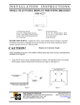
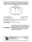
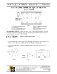
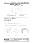
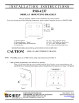
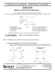
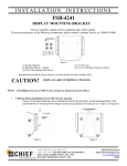
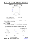
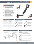
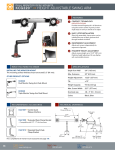
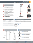
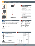
INSTALLATION
INSTRUCTIONS
SMALL FLAT PANEL DISPLAY MOUNTING BRACKET
FSB-4244
(1) Adapter Bracket
(2) Securing Brackets
(6) M4 X 5mm Phillips Pan Head Screws
(2) M3 X 8mm Phillips Pan Head Screws
BEFORE PROCEEDING: Unpack the carton, verify contents shown in Figure 1 and read
installation instructions completely. If you are missing any of the listed components, please
contact Customer Service at 1-800-582-6480.
CAUTION!
WARNING!
Displays are Extremely Fragile.
ALL COMPONENTS MUST BE SECURELY FASTENED TO A
STRUCTURAL MEMBER CAPABLE OF SUPPORTING 4
TIMES THE COMBINED WEIGHT OF ALL COMPONENTS
PLUS THE EQUIPMENT BEING MOUNTED. IF IT CANNOT
SUPPORT THIS WEIGHT, THE STRUCTURE MUST BE
REINFORCED.
THE MAXIMUM WEIGHT TO BE INSTALLED ON THE
BRACKET IS 40 POUNDS (18.14 KG).
Interface installation:
1.
Attaching bracket to Screen: Remove flip out table stand (if attached) by removing
the two Phillips head screws. Attach the adapter bracket to the screen using the
provided M3 x 8 Phillips head screws (Fig.1).
Fig.1
CHIEF MANUFACTURING INC.
1-800-582-6480 952-894-6280 FAX 952-894-6918
8401 EAGLE CREEK PKWY, STE. 700
SAVAGE, MINNESOTA 55378 USA
8804-000354
2007 Chief Manufacturing
www.chiefmfg.com
10/07
2.
Attaching the Securing Brackets: Attach the Securing Brackets using two M4 X 5
Phillips head screws (Fig.2). Adjust securing bracket using the slot so that it is firmly
against the bottom of the screen.
Fig.2
2.
Attaching screen to Cetris mount: Screw M4 x 5mm Phillips head screws part way
into the top two threaded holes. The screws will fit into the top slots on the centris
mount. The top screws can them be tightened and the bottom screws inserted and
secured as well (Fig. 3).
3.
Attaching screen to FSM or FSR: Using the Mounting buttons, M4 x 20mm
Phillips head screw and .74 x .25 x .25 Nylon spacer from the FSR/FSM hardware
kit, attach the mounting button and nylon spacer to the adapter bracket (Fig. 4).
Fig. 3
Fig. 4