1
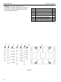
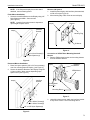
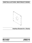
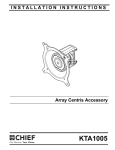
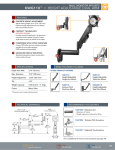
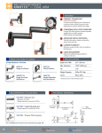
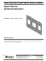
INSTALLATION INSTRUCTIONS
Model FSB-4101
INTERFACE BRACKET
VESA 200mm x 100mm / 100mm x 100mm
BEFORE YOU BEGIN
Prior to assembly, unpack carton completely and verify contents.
If you are missing any of the following components, or you have any questions about this installation, contact Chief
Manufacturing Customer Service at 1-800/582-6480
CHIEF MANUFACTURING INC.
1-800-582-6480 952-894-6280 FAX 952-894-6918
8401 EAGLE CREEK PARKWAY, STE 700
SAVAGE, MINNESOTA 55378 USA
PART NO. 8804-000034 (Rev. E)
©2005 Chief Manufacturing
www.chiefmfg.com
Printed in USA 09/05
Model FSB-4101
Installation Instructions
WARNING: FLAT PANEL DISPLAYS ARE
EXTREMELY FRAGILE. If Display Uses a Screw Size
Other Than M4, DO NOT USE M4 Screws provided.
Monitor Damage Could Occur.
80
30
70
20
60
40
ITEM
50
Figure 1:
2
DESCRIPTION
QTY.
10
Interface Bracket
1
20
3/8" Nylon Spacers
6
30
3/4" Nylon Spacers
6
40
1/8" Nylon Spacers
6
50
M4 X 12mm Phillips Pan Head Screws
6
60
M4 X 20mm Phillips Pan Head Screws
6
70
M4 X 30mm Phillips Pan Head Screws
6
80
M4 X 6mm Phillips Pan Head Screws
6
10
Model FSB-4101
Installation Instructions
NOTE: If the flat panel display has a table stand
attached, remove existing stand.
Flush Mount Installation
1. Secure the Interface Bracket to the Display using 1/8"
Nylon Spacers and M4 x 12mm screws
(see Figure 2).
NOTE: Length of mounting screws is dependant
upon length of spacer used.
Mount to Q2 System
1. Install flat panel display, with interface plate attached,
on Q2 mount (see Figure 4).
2. Move latching flag of Q2 mount to secure display.
Interface
Bracket
Display
Interface
Bracket
Display
Latching Flag
Q2 Mount
Figure 4:
M4 x 12mm Screws(6)
1/8" Nylon Spacers (6)
Conversion to VESA 75mm Mounting/Centris®
Mounts
1. Remove Phillips head screws and mounting buttons
from the interface bracket.
Figure 2:
Recessed Mount Installation
1. Place four Nylon spacers (3/8" or 3/4" as necessary)
over four mounting holes in Display (see Figure 3).
Interface
Bracket
Display
2. Secure the Interface Bracket to the Display using M4
x 20mm or M4 x 30mm screws depending upon
spacer used. (see Figure 3).
VESA Mount
Interface
Bracket
Display
Phillips Head
Screw (4)
Mounting Button
Figure 5:
M4 x 20mm Screws(6)
M4 x 30mm Screws(6)
2. Using M4 x 6mm screws, attach the interface bracket
to any VESA 75mm x 75mm mounting device.
3/8" or 3/4" Nylon Spacers(6)
Figure 3:
3
Model FSB-4101
4
Installation Instructions