1
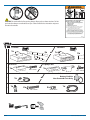
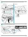
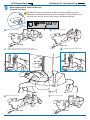
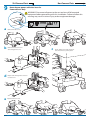
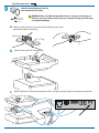
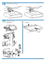
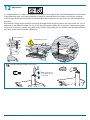
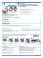
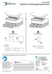
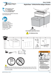
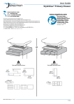
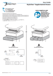
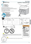
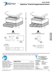
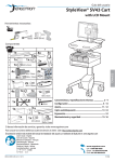
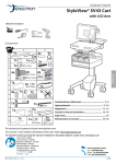
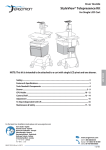
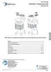
User Guide
StyleView® SV43/44 Primary Drawer
or
< 2 lbs (1 kg)
Total weight capacity per drawer.
2.5"
(64 mm)
<0.25 lbs (0.1 kg)
Total weight capacity per drawer.
10.5"
10.5"
(267 mm)
(267 mm)
12.5"
(315 mm)
3.75"
(96 mm)
For the latest User Installation Guide please visit: www.ergotron.com
User's Guide - English
Guía del usuario - Español
Manuel de l’utilisateur - Français
Gebruikersgids - Deutsch
Benutzerhandbuch - Nederlands
Guida per l’utente - Italiano
Användarhandbok - svenska
ユーザーガイド : 日本語
用户指南 : 汉语
888-97-357-G-00 rev. A • 09/14
1/12
WARNING
14mm (9/16”)
IMPACT HAZARD!
MOVING PARTS CAN CRUSH AND CUT.
Minimize Lift Tension BEFORE:
· Removing Mounted Equipment.
· Shipping Cart
· Storing Cart
CAUTION: Close worksurface before opening drawers. Open only one drawer at a time. Do Not
push cart when drawers or worksurface are open. Failure to follow these instructions may cause
the cart to be unstable.
To Minimize Lift Tension
1. Lower worksurface to lowest position.
2. Turn adjustment nut at top of riser
counterclockwise until it stops
(Adjustment may require 40-60 revolutions).
Failure to heed this warning may result in
serious personal injury or property damage!
For More information and instructions refer to product
guide at http://4support.ergotron.com or contact
Ergotron Customer Care at 1-800-888-8458.
822-052
A
1 Drawer
3 Drawers
1x
3x
1x
or
9x
1
3x
LCD Carts
2
Laptop Carts
2x
1x
M4 x 14mm
or 1x
Powered Carts
3
1x
4
1x
2x
1x
Battery Pack for
Non-Powered Carts Only
1x
2x
M6 x 43mm
M3 x 14mm
Non-Powered Carts
or
1x
4x
M6 x 10mm
14mm (9/16")
2/12
888-97-357-G-00 rev. A • 09/14
1
a
WARNING! Disconnect all power to the cart and turn off all mounted equipment before
proceeding with this installation. Failure to follow this warning may result in serious injury and or
equipment damage.
Turn off all mounted equipment.
2
3
b
c
Disconnect Power System from power source.
Turn power system off by
holding down the AC Outlet
Power button for 1 - 3 seconds.
Power light will shut off.
Remove the
top cover.
Hang the drawer tabs
onto the brackets on
the cart.
2x
b
M6 x 43mm
c
2x
M6 x 10mm
888-97-357-G-00 rev. A • 09/14
3/12
4
5
4/12
Open worksurface.
Laptop Carts
LCD Carts
Route the USB cable from the drawer controller to the USB hub located inside the cart storage area.
888-97-357-G-00 rev. A • 09/14
6
Attach drawer keypad.
Laptop Carts
LCD Carts
or
1x
2x
M4 x 14mm
1x
1x
4x
M3 x 14mm
888-97-357-G-00 rev. A • 09/14
5/12
7
Route the keypad cable through the bottom of the storage area to the drawer controller.
Laptop Carts
8
6/12
or
LCD Carts
Plug the keypad's cable into the drawer controller.
888-97-357-G-00 rev. A • 09/14
LiFe Powered Carts
9
SLA Powered Carts / Non-Powered Carts
Route drawer power cable into base for
Powered Carts Only
WARNING! Disconnect all power to the cart and turn off all mounted
equipment before proceeding with this installation. Failure to follow this
warning may result in serious injury and or equipment damage.
a
Remove rear base cover.
b
REAR VIEW
c
e
FRONT VIEW
d
Remove cable management cover and route drawer
power cable down into base and connect to power system.
Replace front base cover.
FRONT VIEW
888-97-357-G-00 rev. A • 09/14
Remove front base cover.
f
Reattach cable management cover.
Replace rear base cover.
REAR VIEW
7/12
SLA Powered Carts
9
Non-Powered Carts
Route drawer power cable into base for
Powered Carts Only
WARNING! Disconnect all power to the cart and turn off all mounted
equipment before proceeding with this installation. Failure to follow this
warning may result in serious injury and or equipment damage.
a
b
d
e
8/12
Remove front base cover.
Remove rear base cover and
cable management cover.
c
Route drawer power cable down into
base and connect to power system.
Replace cable management cover and
rear base cover.
Replace front base cover.
888-97-357-G-00 rev. A • 09/14
Non-Powered Carts
9
How To Attach Battery Pack for
Non-Powered Carts Only
6x
a
AA
Rechargeable
Nickel Metal
Hydride
WARNING! Only use NiMh rechargeable batteries. Using any other types of
batteries may cause them to leak, rupture, or explode causing personal injury
or equipment damage.
Make sure all 6 batteries are in the drawer battery pack, then
peel off the adhesive backing.
b
Attach battery pack in storage area.
c
Route cable down through the bottom of the storage area and plug into the drawer controller.
888-97-357-G-00 rev. A • 09/14
9/12
10
11
10/12
Replace top cover on drawer.
Replace worksurface.
Laptop Carts
or
LCD Carts
888-97-357-G-00 rev. A • 09/14
12
Adjustment
It is important that you adjust this product according to the weight of the mounted equipment as described
in the following steps. Any time equipment is added or removed from this product, resulting in a change
in the weight of the mounted load, you should repeat these adjustment steps to ensure safe and optimum
operation.
Adjustments should move smoothly and easily through the full range of motion and stay where you set it. If
adjustments are difficult and do not stay in the desired position, follow the instructions to loosen or tighten
the tension to create a smooth, easy adjustment motion. Depending on your product and the adjustment, it
may take several turns to notice a difference.
Lift – Up and down
Release Brake to move riser.
Follow these instructions to tighten or loosen tension.
14mm (9/16")
888-97-357-G-00 rev. A • 09/14
NOTE: Adjustment
may require 40 - 60
revolutions.
11/12
13
NOTE: User should change Master Personal Identification Number (PIN)
upon receipt of cart.
1x
Ensure that the main power system batteries are installed and
functioning. The power does not need to be turned on at the power
system user interface.
Lost Master PIN
Contact Ergotron Customer Care for instructions.
All PINs may vary in length from 4 – 7 digits. Number of PINs possible:
- Carts using StyleLink will store up to 1,000 PINs on the cart
- Carts not using StyleLink will store up to 100 PINs on the cart
- Ergotron recommends the following for choosing PIN digit length (assumes less than 1 in 25
chance of guessing random User PIN):
Max number of User PINs >50, 5+digit length recommended
Max number of User PINs >300, 6+digit length recommended
For maximum security use PIN length of 7
CAUTION: Close worksurface before opening drawers.
Open only one drawer at a time. Do Not push cart when
drawers or worksurface are open. Failure to follow these
instructions may cause the cart to be unstable.
Set-up Master PIN for the First Time (Default Master PIN: 12345)
Contact Ergotron Customer Care for instructions if Master PIN is lost.
1. Enter default Master PIN (1-2-3-4-5) then press ENTER.
2. Press 5 for Master PIN Entry mode
3. Enter new Master PIN and press Enter (LEDs will blink green if PIN is accepted)
4. Master PIN entry mode will exit after 5 seconds of inactivity (LEDs blink red twice)
Master PIN Mode Menu
Enter Master PIN and then select one of the below numbers to enter that mode
1. User PIN Entry Mode
2. Pharmacy PIN Entry/Change Mode
5. Master Pin Change Mode
Programming User PINS
1. Enter Master PIN and press ENTER for Mode Menu.
2. Press 1 for User PIN Entry Mode.
3. Input new User PIN and press ENTER (All LEDs blink green if PIN is accepted). You may enter multiple USER PINs consecutively.
4. User PIN entry mode will exit after 5 seconds of inactivity (LEDs blink red twice).
NOTE: User PIN cannot be the same as a Master PIN or Pharmacy PIN. Once maximum User PIN storage is exceeded, the oldest User PIN will be over written.
Programming Pharmacy PIN
1. Enter Master PIN and press ENTER for Mode Menu
2. Press 2 for Pharmacy PIN Entry Mode
3. Input Pharmacy PIN and press ENTER (all LEDs blink green in PIN is accepted).
4. Pharmacy PIN entry mode will exit after 5 seconds of inactivity (LEDs blink
red twice).
Note: System will hold 1 Pharmacy PIN. Pharmacy PIN allows all drawers to unlock at the
same time. Drawers should then be opened at least slightly as the system will auto-lock after
10 seconds. All LEDs will flash green until system auto-locks. Once a drawer is opened the
corresponding LED for that row will light solid until it is placed back into its original location.
Unlock Drawer (2 methods): NOTE: All Drawers in row must be closed before a new row can be unlocked.
• Enter User PIN (only numbers for available drawer rows flash green), then press desired drawer row number*.
• Key - turn clockwise 1/4 turn
*Drawer Row Numbers:
1
1
1
2
1
2
1
2
2
3
Lock Drawer:
• Wait 4 seconds for lock to engage automatically.
NOTE: Always ensure drawer is pushed in all the way and engaged with lock.
Drawer Troubleshooting
• No LEDs on keypad when pressing any number:
•Verify DC cable is connected from cart battery harness to controller.
• Verify keypad cable is connected to controller.
• Verify circuit breakers are not tripped and 5A fuse is installed in
battery harness.
• Drawer selection not available when User PIN is entered:
• Check to make sure drawer cable is installed securely.
• Remove power from drawer system for 10 seconds and re-apply.
• LEDs flash red/green after User PIN in entered:
• Battery charge is low, check to make sure USB charging cable is
plugged into computer and computer is ON.
12/12
LEDs/Alarm Meaning:
1,2,3,4, or 5 LED ON green: Corresponding Drawer is open.
1,2,3,4, or 5 LED flashing red and alarm sounding: Corresponding Drawer is open longer than 20
seconds. Mute alarm by pressing flashing button corresponding to open drawer.
All available drawer numbers flashing green: Waiting for drawer selection (see Unlock Drawer).
All LEDs flashing green: Pharmacy mode, all drawers are unlocked.
All LEDs blink red twice: PIN entry rejected/exit current mode after 5 seconds timeout.
All LEDs blink green 3 times: PIN entry accepted.
All LEDs flashing red: Firmware update in progress.
All LEDs flashing red/green: System power ON or low battery condition.
888-97-357-G-00 rev. A • 09/14