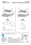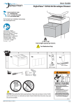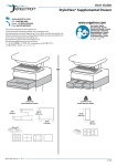
1
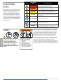
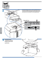
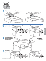
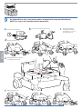
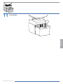
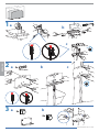
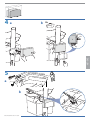
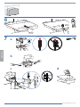
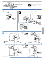
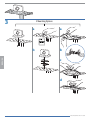
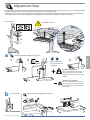
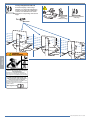
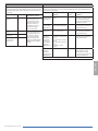
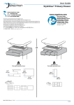
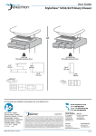
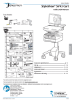
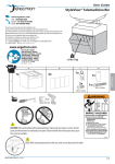
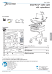
User Guide
StyleView® Telepresence Kit
for Single LCD Cart
Safety........................................................................................................................ 2
Features & Specifications ...................................................................................................... 3
Tools Needed & Components ................................................................................................4
Drawer ................................................................................................................................ 5 - 9
CPU Holder .....................................................................................................................10 - 12
Camera Shelf ..................................................................................................................13 - 14
Adjustment .......................................................................................................................... 15
To Stop Independent LCD Lift..............................................................................................16
Maintenance & Safety ...................................................................................................17 - 18
For the latest User Installation Guide please visit: www.ergotron.com
User's Guide - English
Guía del usuario - Español
Manuel de l’utilisateur - Français
Gebruikersgids - Deutsch
Benutzerhandbuch - Nederlands
Guida per l’utente - Italiano
Användarhandbok - svenska
ユーザーガイド : 日本語
用户指南 : 汉语
888-97-333-G-00 rev. A • 09/13
1 of 18
ENGLISH
NOTE: This kit is intended to be attached to a cart with single LCD pivot and one drawer.
Symbol
Hazard Symbols
Review
Signal Word/
Color
DANGER
These symbols alert users of a safety condition that demands attention. All users should
be able to recognize and understand the
significance of the following Safety Hazards
if encountered on the product or within the
documentation. Children who are not able to
recognize and respond appropriately to Safety
Alerts should not use this product without
adult supervision!
Indicates a potentially hazardous situation which, if not
avoided, could result in death or serious injury.
CAUTION
Indicates a potentially hazardous situation which, if not
avoided, may result in minor or moderate injury.
CAUTION
Used without the safety alert symbol indicates a potentially
hazardous situation which, if not avoided, may result in
property damage.
INSTRUCTIONS
Follow operating instructions.
INSTRUCTIONS
Follow operating instructions.
WARNING
ENGLISH
14mm (9/16”)
CAUTION: Close worksurface before
opening drawers. Open only one
drawer at a time. Do Not push
cart when drawers or worksurface
are open. Failure to follow these
instructions may cause the cart to be
unstable.
Indicates an imminently hazardous situation which, if not
avoided, will result in death or serious injury.
WARNING
POWER
Safety
Level of Hazard
IMPACT HAZARD!
MOVING PARTS CAN CRUSH AND CUT.
Minimize Lift Tension BEFORE:
· Removing Mounted Equipment.
· Shipping Cart
· Storing Cart
To Minimize Lift Tension
1. Lower worksurface to lowest position.
2. Turn adjustment nut at top of riser
counterclockwise until it stops
(Adjustment may require 40-60 revolutions).
"ON" / "OFF" (push-push)
NOTE: Each position "ON" / "OFF" is a stable position.
Important! You will need to adjust this product after installation
is complete. Make sure all your equipment is properly installed
on the product before attempting adjustments. This product
should move smoothly and easily through the full range of
motion and stay where you set it. If movements are too easy
or difficult or if product does not stay in desired positions,
follow the adjustment instructions to create smooth and easy
movements. Depending on your product and the adjustment,
it may take many turns to notice a difference. Any time
equipment is added or removed from this product, resulting in
a change in the weight of the mounted load, you should repeat
these adjustment steps to ensure safe and optimum operation.
Failure to heed this warning may result in
serious personal injury or property damage!
For More information and instructions refer to product
guide at http://4support.ergotron.com or contact
Ergotron Customer Care at 1-800-888-8458.
822-052
888-97-333-G-00 rev. A • 09/13
2 of 18
Features & Specifications
11.8"
(300 mm)
Weight Capacity
With Independent LCD Lift:
6-14 lbs (2.7-6.4 kg)
Without Independent LCD Lift:
20 lbs (9 kg)*
* See "How To Eliminate Independent LCD
Lift" section
0 lbs (0 kg) Open Worksurface
<5 lbs (2.3 kg) Closed Worksurface
<13 lbs (5.9 kg) CPU Compartment
<2 lbs (0.9 kg)
<2 lbs (0.9 kg)
<2 lbs (0.9 kg)
< 2 lbs (1 kg)
<25 lbs (11.3 kg)
1.38" - 3.75"
(35-95 mm)
*Combined LCD and CPU Compartment weight: <27
lbs (12.2 kg).
CAUTION:
If the combined LCD and CPU weight is greater than 27 lbs (12.2 kg) then the CPU must
be mounted to the rear of the cart using the Universal CPU Holder accessory (ordered
separately).
ENGLISH
888-97-333-G-00 rev. A • 09/13
3 of 18
Tools Needed
10mm
14mm (9/16")
Components
A
1
2
B
C
D
E
1x
1x
1x
1x
1x
1x
M4 x 6mm
M4 x 14mm
2x
1x
M4 x 25mm
4x
3
A
B
1x
C
D
1x
1x
1x
1
2x
1x
ENGLISH
M3 x 22mm
M4 x 12mm
A
1x
1
B
C
1x
D
E
12x
2x
F
2x
M5 x 10mm
2x
10-24 x 1/2”
2x
888-97-333-G-00 rev. A • 09/13
4 of 18
1
Attach the Travel Stop bracket to the lift engine to keep the
drawer from hitting the base.
a
2
1x
M3 x 22mm
b
Slide the drawer only half way onto the bottom
tracks of the existing top drawer.
ENGLISH
888-97-333-G-00 rev. A • 09/13
5 of 18
Remove the top cover on the top drawer and
route the cable attached to the bottom drawer
up into the control panel on the top drawer.
3
Powered Carts
ENGLISH
Non-Powered Carts
4
Slide the drawer
completely onto the
bottom tracks of the
top drawer.
888-97-333-G-00 rev. A • 09/13
6 of 18
5
Replace the top cover on the top drawer.
7
Secure the bottom
drawer by attaching
the two screws.
8
Replace the
top drawer(s).
ENGLISH
6
Remove the
top drawer(s).
2x
M4 x 12mm
888-97-333-G-00 rev. A • 09/13
7 of 18
9
ENGLISH
a
On Powered Carts only, reset drawer power so keypad will recognize added drawer.
NOTE: This step is not needed on Non-Powered Carts.
Turn off all mounted equipment.
d
Remove front base cover.
e
Unplug drawer power cable and
then plug it back in to reset.
f
b
Disconnect Power System from power source.
c
Turn power system off by
holding down the AC Outlet
Power button for 1 - 3 seconds.
Power light will shut off.
Replace front base cover.
888-97-333-G-00 rev. A • 09/13
8 of 18
11
Insert divider.
ENGLISH
888-97-333-G-00 rev. A • 09/13
9 of 18
1a
b
c
ENGLISH
180˚
2a
b
2x
c
M5 x 10mm
3a
4x
b
8x
888-97-333-G-00 rev. A • 09/13
10 of 18
4a
b
2x
ENGLISH
5
a
b
888-97-333-G-00 rev. A • 09/13
11 of 18
6
ENGLISH
7
a
b
c
d
888-97-333-G-00 rev. A • 09/13
12 of 18
NOTE: camera is supplied
by customer.
Max weight: 2 lbs (1 kg)
1x
2
a
M4 x 6mm
If your monitor has recessed mounting holes,
you need to add the provided spacer between
the monitor and the mounting plate.
ENGLISH
1
b
2x
M4 x 14mm
c
d 2x
M4 x 14mm
888-97-333-G-00 rev. A • 09/13
13 of 18
ENGLISH
3
3 Mounting Options
a
a
b
b
c
d
888-97-333-G-00 rev. A • 09/13
14 of 18
Adjustment Step
It is important that you adjust this product according to the weight of the mounted equipment as described in the following steps. Any time equipment is added or removed from this product, resulting
in a change in the weight of the mounted load, you should repeat these adjustment steps to ensure safe and optimum operation.
Adjustments should move smoothly and easily through the full range of motion and stay where you set it. If adjustments are difficult and do not stay in the desired position, follow the instructions to
loosen or tighten the tension to create a smooth, easy adjustment motion. Depending on your product and the adjustment, it may take several turns to notice a difference.
Lift – Up and down
Release Brake to move riser.
a
Follow these instructions to tighten or loosen tension.
2
14mm (9/16")
NOTE: Adjustment
may require 40 - 60
revolutions.
ENGLISH
1
3
Increase Lift Strength
If the mounted weight is too heavy or
this product does not stay up when
raised, then you'll need to increase Lift
Strength:
Decrease Lift Strength
If the mounted weight is too light or
this product does not stay down when
lowered, then you'll need to decrease
Lift Strength:
b
Lift – Up and down
Follow these instructions to tighten or loosen tension.
10mm
888-97-333-G-00 rev. A • 09/13
15 of 18
To Stop Independent LCD Lift
For heavier Displays or when using a
Tablet PC, you can keep the LCD Lift from
moving out of position, by installing this
screw into one of the three holes on the
back of the riser depending on the desired
height.
With Independent
LCD Lift:
6-14 lbs (2.7-6.4 kg)
1x
Without Independent LCD Lift:
20 lbs (9 kg)
M4 x 8mm
WARNING
AVERTISSEMENT
ENGLISH
1.
2.
3.
IMPACT HAZARD!
MOVING PARTS CAN CRUSH AND CUT.
Failure to heed this warning may result in serious personal
injury or property damage!
Raise monitor to top of vertical adjustment BEFORE removing.
DO NOT remove Stop Screw without monitor attached. Doing so will
cause monitor pivot to shoot up rapidly and may cause personal injury.
DANGER D’IMPACT !
LES PARTIES EN MOUVEMENT PEUVENT ÉCRASER ET COUPER.
Il existe un risque de blessure corporelle ou d’endommagement
matériel en cas de non respect de cet avertissement.
Élevez l’écran au plus haut de l’ajustement vertical AVANT de le retirer.
NE retirez PAS la vis d’arrêt avant que l’écran soit fixé.
Dans un tel cas, le pivot d'écran se relèverait rapidement et cela pourrait
engendrer des blessures.
www.ergotron.com
826-502
888-97-333-G-00 rev. A • 09/13
16 of 18
Guidance and Manufacturer’s Declaration – Electromagnetic Emissions
Guidance and Manufacturer’s Declaration – Electromagnetic Immunity
Ergotron's Medical Grade Power Strip is intended for use in the
electromagnetic environment specified below. The customer or the user
of the Medical Grade Power Strip should assure that it is used in such an
environment.
Ergotron's Medical Grade Power Strip is intended for use in the electromagnetic environment
specified below. The customer or the user of the Medical Grade Power Strip should assure that it is
used in such an environment.
Emissions Test
Compliance
Electromagnetic
environment – guidance
RF Emissions
CISPR 11
Group 1
Ergotron's Medical Grade
Power Strip does not use
RF energy for its internal
function. Therefore, its RF
emissions are very low
and unlikely to cause any
interference in nearby
electronic equipment.
RF Emissions
CISPR 11
Class B
Harmonic Emissions
IEC 61000-3-2
Class B
Voltage fluctuations/
flicker emissions
IEC 61000-3-3
Complies
Ergotron's Medical Grade
Power Strip is suitable for use
in all establishments other
than domestic and those
directly connected to the
public low-voltage power
supply network that supplies
buildings used for domestic
purposes.
Immunity Test
IEC 60601
Test Level
Compliance
Level
Electromagnetic environment
- guidance
Electrostatic
Discharge (ESD)
IEC 61000-4-2
±6 kV contact
±8 kV air
Complies
Floors should be wood,
concrete, or ceramic tile. If floors
are covered with synthetic
material, the relative humidity
should be at least 30%
Electrical Fast
Transient/Burst
IEC 61000-4-3
±2 kV for power supply lines
±1 kV for input/output lines
Complies
Mains power quality should be
that of a typical commercial or
hospital environment.
Surge
IEC 61000-4-5
±1 kV differential mode
±2 kV common mode
Complies
Mains power quality should be
that of a typical commercial or
hospital environment
Voltage
Dips, short
interruptions,
and voltage
variations on
power supply
input lines
IEC 61000-4-11
<5% UT
(>95% dip in UT) for 0.5 cycle
40% UT
(60% dip in UT) for 5 cycles
70% UT
(30% dip in UT) for 25 cycles
<5% UT
(>95% dip in UT) for 5
seconds
Complies
Mains power quality should be
that of a typical commercial or
hospital environment.
Power
Frequency
(50/60 Hz)
Magnetic Field
IEC 61000-4-8
3 A/m
Complies
Power frequency magnetic
fields should be at levels
characteristic of a typical
location in a typical commercial
or hospital environment.
Note: UT is the AC mains voltage prior to application of the test level
ENGLISH
888-97-333-G-00 rev. A • 09/13
17 of 18
Safety Alerts Associated with this Product
The following Warnings/Cautions appear in this reference guide or on the Power Strip. NOTE: Failure to adhere to these guidelines may result in equipment damage or personal
injury.
Cleaning and Maintenance
The following procedures are not guaranteed to control infection. The hospital infection control administrator or epidemiologist should be consulted regarding cleaning
procedures and processes.
To avoid risk of electric shock, do not expose electrical components to water, cleaning solutions or other potentially corrosive liquids or substances.
Do not immerse Power Strip or Power Strip components in liquid or allow liquids to flow into the Power Strip. Wipe all cleaners off surface immediately using a damp cloth.
Thoroughly dry surface after cleaning.
Do not use flammable cleaners on Power Strip surfaces due to close proximity of electrical power and equipment.
All paints and plastic Power Strip components will withstand cleaning by most commonly used, diluted, non-abrasive solutions such as quaternary ammonia compounds,
ammonia enzyme cleaners, bleach or alcohol solutions.
• Pen and permanent and dry erase markers can be removed with 91% isopropyl alcohol and a soft cloth.
• Iodine stains can be removed with commonly used cleaners and a soft cloth.
• Never use steel wool or other abrasive materials that will damage the surface finish.
It is recommended that any cleaning solution be tested on a small, inconspicuous area to ensure surface is not harmed.
Adjustment, Service, Replacement - DO NOT attempt to adjust, service or replace any part of the Power Strip unless directed to do so through Ergotron-approved
documentation (i.e. installation instructions). Only Ergotron, Inc. or an Ergotron-certified entity may adjust, service or replace Power Strip components. If any component on the
Power Strip is missing or damaged, the Power Strip must not be used, contact Ergotron Customer Care immediately to request a replacement part.
Cables - Keep cables neatly organized (the provided Strain Relief and Hook are designed for this purpose). Excess cables should be routed away from moving components
with cable clips or ties. Review Cable Routing section of this guide, or contact Ergotron Customer Care for more information.
Customer Equipment- Do not connect electrical equipment beyond rated ....
Customer Equipment- Only cart-mounted electrical equipment should be connected to Power Strip.
The polarized cord on this Power Strip is Hospital Grade Only. Grounding reliability can only be achieved when the equipment is connected to an equivalent receptacle
marked "Hospital Only" or "Hospital Grade".
ENGLISH
The device is not suitable for use in the presence of a flammable anaesthetic mixture with air or with oxygen or nitrous oxide.
For local customer care phone numbers visit: http://contact.ergotron.com
888-97-333-G-00 rev. A • 09/13
18 of 18