1
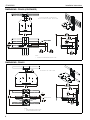
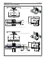
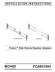
INSTALLATION INSTRUCTIONS
to Wall Mount
to Cart/Ceiling mount
to Above/Below Shelf
(FCA821 shown)
Fusion™ Center Accessory Shelf
Spanish Product Description
German Product Description
Portuguese Product Description
Italian Product Description
Dutch Product Description
French Product Description
FCA820/821
FCA820/821
DISCLAIMER
Milestone AV Technologies and its affiliated corporations and
subsidiaries (collectively “Milestone”), intend to make this
manual accurate and complete. However, Milestone makes no
claim that the information contained herein covers all details,
conditions or variations, nor does it provide for every possible
contingency in connection with the installation or use of this
product. The information contained in this document is subject
to change without notice or obligation of any kind. Milestone
makes no representation of warranty, expressed or implied,
regarding the information contained herein. Milestone assumes
no responsibility for accuracy, completeness or sufficiency of
the information contained in this document.
Chief® is a registered trademark of Milestone AV Technologies.
All rights reserved.
IMPORTANT SAFETY INSTRUCTIONS
WARNING: A WARNING alerts you to the possibility of
serious injury or death if you do not follow the instructions.
CAUTION: A CAUTION alerts you to the possibility of
damage or destruction of equipment if you do not follow the
corresponding instructions.
WARNING: Failure to read, thoroughly understand, and
follow all instructions can result in serious personal injury,
damage to equipment, or voiding of factory warranty! It is the
installer’s responsibility to make sure all components are
properly assembled and installed using the instructions
provided.
WARNING: Exceeding the weight capacity can result in
serious personal injury or damage to equipment! It is the
installer’s responsibility to make sure the combined weight
mounted to the FCA820/821 shelves does not exceed 10 lbs
(4.5 kg).
WARNING: Use this mounting system only for its intended
use as described in these instructions. Do not use
attachments not recommended by the manufacturer.
WARNING: Never operate this mounting system if it is
damaged. Return the mounting system to a service center for
examination and repair.
WARNING: Do not use this product outdoors.
WARNING: RISK OF INJURY TO PERSONS! Do not use
this mounting system to support video equipment such as
televisions or computer monitors.
--SAVE THESE INSTRUCTIONS-2
Installation Instructions
Installation Instructions
FCA820/821
DIMENSIONS - FCA820
FUSION WALL MOUNT SETUP
OVERALL MIN
0.50
12.7
MAX ABOVE
EXTENSION
9.81
249.2
OVERALL
WIDTH
MIN SHELF
CENTER OF MOUNT
0.50
12.7
MAX BELOW
EXTENSION
*NOTES:
•
•
FIXED FUSION INTERFACES ARE 0.5" DEEP
TILT FUSION INTERFACES ARE 0.5" DEEP
FUSION CEILING/CART MOUNT SETUP
0.50
12.7
MAX ABOVE
EXTENSION
7.88
200.0
OVERALL
WIDTH
MIN SHELF
DEPTH*
CENTER OF MOUNT
0.50
12.7
MAX BELOW
EXTENSION
*NOTES:
•
FCA623 DUAL MONITOR INTERFACES ARE 1.4" DEEP
3
FCA820/821
Installation Instructions
DIMENSIONS - FCA820 (CONTINUED)
FUSION CEILING/CART MOUNT
WITH ABOVE OR BELOW SHELF SETUP
8.00
203.2
*NOTES:
•
FCA623 DUAL MONITOR INTERFACES ARE 1.4" DEEP
DIMENSIONS - FCA821
FUSION WALL MOUNT SETUP
OVERALL MIN
0.50
12.7
MAX ABOVE
EXTENSION
9.81
249.2
OVERALL
WIDTH
CENTER OF MOUNT
0.50
12.7
MAX BELOW
EXTENSION
*NOTES:
•
•
4
FIXED FUSION INTERFACES ARE 0.5" DEEP
TILT FUSION INTERFACES ARE 0.5" DEEP
MIN SHELF
Installation Instructions
FCA820/821
DIMENSIONS - FCA821 (CONTINUED)
FUSION CEILING/CART MOUNT SETUP
0.50
12.7
MAX ABOVE
EXTENSION
7.88
200.0
OVERALL
WIDTH
MIN SHELF
DEPTH*
CENTER OF MOUNT
0.50
12.7
MAX BELOW
EXTENSION
*NOTES:
•
FCA623 DUAL MONITOR INTERFACES ARE 1.4" DEEP
FUSION CEILING/CART MOUNT
WITH ABOVE OR BELOW SHELF SETUP
14.00
355.6
*NOTES:
•
FCA623 DUAL MONITOR INTERFACES ARE 1.4" DEEP
5
FCA820/821
Installation Instructions
LEGEND
Tighten Fastener
Phillips Screwdriver
Apretar elemento de fijación
Destornillador Phillips
Befestigungsteil festziehen
Kreuzschlitzschraubendreher
Apertar fixador
Chave de fendas Phillips
Serrare il fissaggio
Cacciavite a stella
Bevestiging vastdraaien
Kruiskopschroevendraaier
Serrez les fixations
Tournevis à pointe cruciforme
Loosen Fastener
Open-Ended Wrench
Aflojar elemento de fijación
Llave de boca
Befestigungsteil lösen
Gabelschlüssel
Desapertar fixador
Chave de bocas
Allentare il fissaggio
Chiave a punte aperte
Bevestiging losdraaien
Steeksleutel
Desserrez les fixations
Clé à fourche
Hex-Head Wrench
Llave de cabeza hexagonal
Sechskantschlüssel
Chave de cabeça sextavada
Chiave esagonale
Zeskantsleutel
Clé à tête hexagonale
TOOLS REQUIRED FOR INSTALLATION
1/8” (included)
5/32” (included)
#2
PARTS
C (4)
D (2)
1/4-20 x 3/8” #10-32 x 1/4”
A (1)
[FCA820/821 shelf]
B (1)
[Center plate]
G (4)
1/4-20 x 1 1/4”
F (2)
[Center holder]
E (8)
1" adhesive
hook and loop
L (1)
5/32”
J (4)
1/4”
H (1)
1/4-20 x 3/8”
M (1)
1/8”
K (2)
#10
N (4)*
#4x48 x 1/4”
*FCA821 only
6
Installation Instructions
FCA820/821
ASSEMBLY AND INSTALLATION
(to Cart/Ceiling)
Installing to Cart/Ceiling Mount
(FCA820 shown)
NOTE: If installing to Wall Mount, proceed to "Installing to Wall
(F)
Mount" Section. If installing to a FCA810/811 shelf,
proceed to "Installing to FCA810/811 Shelves" section.
1.
Attach FCA820/821 shelf (A) to center plate (B) using two
#10-32 x 1/4” button head cap screws (D) and two #10
washers (K). (See Figure 1)
3
(FCA820 shown)
(D) x 2
1
4
(F)
Figure 3
5.
(K) x 2
Use two 1/4-20 x 3/8” button head cap screws (C) and two
1/4” washers (J) to attach the other center holder (F) to
center plate (B). (See Figure 4)
(B)
(to Cart/Ceiling)
(A)
(FCA820 shown)
Figure 1
2.
Use two 1/4-20 x 3/8” button head cap screws (C) and two
1/4” washers (J) to attach one center holder (F) to center
plate (B). (See Figure 2)
(B)
(J) x 2
(to Cart/Ceiling)
(FCA820 shown)
2
(C) x 2
(F)
(B)
(F)
5
(C) x 2
Figure 4
(J) x 2
Figure 2
3.
Place center holder (F) on top of cart interface. (See Figure
3)
4.
Place second center holder (F) underneath cart interface so
that mounting holes are aligned. (See Figure 3)
7
FCA820/821
Installation Instructions
Installing to Wall Mount
1.
Attach FCA820/821 shelf (A) to center plate (B) using two
#10-32 x 1/4” button head cap screws (D) and two #10
washers (K). (See Figure 5)
(FCA820 shown)
3.
Place center holder (F) on top of wall mount rail. (See Figure
7)
4.
Tighten two screws (G) holding center holder (F) to center
plate (B). (See Figure 7)
5.
Place second center holder (F) underneath wall mount rail
so that mounting holes are aligned. (See Figure 7)
(D) x 2
1
(to Wall)
(F)
(FCA820 shown)
(G) x 2
4
3
(K) x 2
(B)
(A)
(B)
(F)
Figure 5
5
2.
Use two 1/4-20 x 1 1/4” button head cap screws (G) and two
1/4” washers (J) to partially attach one center holder (F) to
center plate (B). Do NOT install screws too far or installation
to wall mount will not be possible. (See Figure 6)
(to Wall)
Figure 7
(FCA820 shown)
(F)
6.
2
(G) x 2
(B)
Use two 1/4-20 x 1 1/4” button head cap screws (G) and two
1/4” washers (J) to attach the other center holder (F) to
center plate (B). (See Figure 8)
(to Wall)
(FCA820 shown)
6
(G) x 2
(B)
(J) x 2
partially installed
screw position
(J) x 2
Figure 8
Figure 6
8
(F)
Installation Instructions
FCA820/821
Installing to FCA810/811 Shelves
3.
(Multiple screw option - FCA821 only) Install four #4-48 x
1/4” Phillips pan machine screws (N) through outside
mounting slots and into holes on bottom of camera. (See
Figure 11)
4.
Route cable from camera towards back of shelf and down
behind the FCA820/821. (See Figure 10) and (See Figure
11)
NOTE: FCA820/821 may be attached to FCA810/811 Above/
Below Shelves.
1.
Install FCA810/811 shelf to mount following FCA810/811
installation instructions.
2.
Use two #10-32 x 1/4” button head cap screws (D) and two
#10 washers (K) to secure FCA820/821 shelf (A) to
FCA810/811 main bracket. (See Figure 9)
FCA810/811
main bracket
2
(FCA820 shown)
Camera
(example not included)
(D) x 2
1 (E) x 4
4
(A)
(K) x 2
Figure 9
Installing Camera (not included)
2
Figure 10
WARNING: Exceeding the weight capacity can result in
serious personal injury or damage to equipment! It is the
installer’s responsibility to make sure the combined weight of
all components located on the FCA820/821 does not exceed
10 lbs (4.5 kg).
(H) x 1
Slots provided
for strap
(not included)
(FAC821 only)
Camera
(example not included)
WARNING: Camera must be secured to FCA820/821 shelf
4
using either adhesive hook and loop squares (E) or screws
(H or N)! Failure to securely mount camera to shelf may result
in serious personal injury or damage to equipment!
NOTE: OPTIONAL: Slots are provided in shelf for strap (not
included) to hold component in place. (See Figure 10)
Using Adhesive Squares
1.
Use up to eight adhesive hook and loop squares (E) to
secure camera to shelf. Attach adhesive squares to bottom
of camera first and then attach corresponding squares to
shelf when the exact mounting location has been
determined. (See Figure 10)
Using Screw(s)
NOTE: Screw mounting options will vary based upon camera
Slots provided
for strap
(not included)
model.
2.
(Single Screw option) Install 1/4-20 x 3/8” Phillips pan
machine screw (H) through mounting slot on shelf and into
hole on bottom of camera. (See Figure 10)
3
(N) x 4
Figure 11
9
FCA820/821
10
Installation Instructions
Installation Instructions
FCA820/821
11
FCA820/821
Installation Instructions
USA/International
Europe
Chief, a products division of
Milestone AV Technologies
8800-002586 Rev00
2014 Milestone AV Technologies
www.chiefmfg.com
05/14
Asia Pacific
A
P
F
A
P
F
A
6436 City West Parkway, Eden Prairie, MN 55344
800.582.6480 / 952.225.6000
877.894.6918 / 952.894.6918
Franklinstraat 14, 6003 DK Weert, Netherlands
+31 (0) 495 580 852
+31 (0) 495 580 845
Office No. 918 on 9/F, Shatin Galleria
18-24 Shan Mei Street
Fotan, Shatin, Hong Kong
P 852 2145 4099
F 852 2145 4477