1
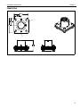
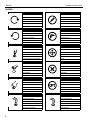
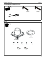
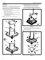
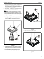
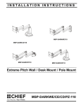
INSTALLATION INSTRUCTIONS
Instrucciones de instalación
Installationsanleitung
Instruções de Instalação
Istruzioni di installazione
Installatie-instructies
Instructions d´installation
Heavy Duty Swivel Adapter
Spanish Product Description
German Product Description
Portuguese Product Description
Italian Product Description
Dutch Product Description
French Product Description
CMA351
CMA351
Installation Instructions
DISCLAIMER
Milestone AV Technologies and its affiliated corporations and
subsidiaries (collectively "Milestone"), intend to make this
manual accurate and complete. However, Milestone makes no
claim that the information contained herein covers all details,
conditions or variations, nor does it provide for every possible
contingency in connection with the installation or use of this
product. The information contained in this document is subject
to change without notice or obligation of any kind. Milestone
makes no representation of warranty, expressed or implied,
regarding the information contained herein. Milestone assumes
no responsibility for accuracy, completeness or sufficiency of
the information contained in this document.
WARNING: The CMA351 mounts are designed to be
mounted to a 1-1/2" NPT or NPSM following ANSI/ASME
B1.20.1 (Schedule 40, 0.154" minimum thickness aluminumASTM B221) threaded extension column.
WARNING: Never operate this mounting system if it is
damaged. Return the mounting system to a service center for
examination and repair.
WARNING: Do not use this product outdoors.
--SAVE THESE INSTRUCTIONS-Chief® is a registered trademark of Milestone AV Technologies.
All rights reserved.
IMPORTANT SAFETY INSTRUCTIONS
WARNING: A WARNING alerts you to the possibility of
serious injury or death if you do not follow the instructions.
CAUTION: A CAUTION alerts you to the possibility of
damage or destruction of equipment if you do not follow the
corresponding instructions.
WARNING: Failure to read, thoroughly understand, and
follow all instructions can result in serious personal injury,
damage to equipment, or voiding of factory warranty! It is the
installer’s responsibility to make sure all components are
properly assembled and installed using the instructions
provided.
WARNING: Failure to provide adequate structural strength
for this component can result in serious personal injury or
damage to equipment! It is the installer’s responsibility to
make sure the structure to which this component is attached
can support five times the combined weight of all equipment.
Reinforce the structure as required before installing the
component.
WARNING: Exceeding the weight capacity can result in
serious personal injury or damage to equipment! It is the
installer’s responsibility to make sure the combined weight of
all components located between the CMA351 up to (and
including) the projector does not exceed 500 lbs (226.8 kg).
•
The weight capacity of the CMA351 may be
LIMITED to the lowest weight capacity of any
other component located between the CMA351
and the supporting structure!
WARNING: Use this mounting system only for its intended
use as described in these instructions. Do not use
attachments not recommended by the manufacturer.
2
Installation Instructions
CMA351
DIMENSIONS
101.600
4.00
50.800
2.00
1 1/2" NPS
BOTH ENDS
50.800
2.00
101.600
4.00
STOP SET SCREW
76.424
3.01
3
CMA351
Installation Instructions
LEGEND
4
Tighten Fastener
Pencil Mark
Apretar elemento de fijación
Marcar con lápiz
Befestigungsteil festziehen
Stiftmarkierung
Apertar fixador
Marcar com lápis
Serrare il fissaggio
Segno a matita
Bevestiging vastdraaien
Potloodmerkteken
Serrez les fixations
Marquage au crayon
Loosen Fastener
Drill Hole
Aflojar elemento de fijación
Perforar
Befestigungsteil lösen
Bohrloch
Desapertar fixador
Fazer furo
Allentare il fissaggio
Praticare un foro
Bevestiging losdraaien
Gat boren
Desserrez les fixations
Percez un trou
Phillips Screwdriver
Adjust
Destornillador Phillips
Ajustar
Kreuzschlitzschraubendreher
Einstellen
Chave de fendas Phillips
Ajustar
Cacciavite a stella
Regolare
Kruiskopschroevendraaier
Afstellen
Tournevis à pointe cruciforme
Ajuster
Open-Ended Wrench
Remove
Llave de boca
Quitar
Gabelschlüssel
Entfernen
Chave de bocas
Remover
Chiave a punte aperte
Rimuovere
Steeksleutel
Verwijderen
Clé à fourche
Retirez
By Hand
Optional
A mano
Opcional
Von Hand
Optional
Com a mão
Opcional
A mano
Opzionale
Met de hand
Optie
À la main
En option
Hex-Head Wrench
Security Wrench
Llave de cabeza hexagonal
Llave de seguridad
Sechskantschlüssel
Sicherheitsschlüssel
Chave de cabeça sextavada
Chave de segurança
Chiave esagonale
Chiave di sicurezza
Zeskantsleutel
Veiligheidssleutel
Clé à tête hexagonale
Clé de sécurité
Installation Instructions
CMA351
TOOLS REQUIRED FOR INSTALLATION
3/32"
(provided)
5/32"
(provided)
PARTS
B (1)
[stop plate]
A (1)
[swivel adapter]
C (2)
.315 x .507 x 090
D (2)
10-24
H (1)
3/32"
E (1)
#8-32 x 1/2"
F (1)
5/16-18 x 3/8"
G (1)
10-24 x 1/4"
J (1)
5/32"
5
CMA351
Installation Instructions
Installation
4.
IMPORTANT ! : These installation instructions assume
that a 1-1/2" NPT or NPSM following ANSI/ASME B1.20.1
Thread swivel adapter (A) onto existing 1-1/2" NPT or
NPSM threaded extension column until tight, with a
minimum of four threads engaged. (See Figure 2)
5.
Secure swivel adapter (A) to extension column using 5/1618 x 3/8" set screw (F) and hex wrench. (See Figure 2)
(Schedule 40, 0.154" minimum thickness aluminum-ASTM
B221) threaded extension column (not included) has been
properly installed and is in place.
1.
Place one Nylon washer (C) over each stud on swivel
adapter (A). (See Figure 1)
2.
Align slots in stop plate (B) with two threaded studs on
swivel adapter (A). (See Figure 1)
3.
(F)
5
Secure stop plate (B) to swivel adapter (A) using two lock
nuts (D). (See Figure 1)
4
NOTE: DO NOT fully tighten lock nuts at this time.
(B)
2
(A)
(C) x 2
Figure 2
1
6.
Rotate the bottom of swivel adapter (A) until middle set
screw in swivel adapter (A) makes contact with tab in stop
plate (B). (See Figure 3)
NOTE: This is considered the first stop position.
(A)
Tab
(Not Visible)
6
Lower Set
Screw
(D) x 2
3
(B)
(A)
(A)
Tab
Lower Set
Screw
TOP VIEW
Figure 1
6
Figure 3
Installation Instructions
CMA351
7.
Using a pipe wrench, install 1-1/2" NPT or NPSM following
ANSI/ASME B1.20.1 (Schedule 40, 0.154" minimum
thickness aluminum - ASTM B221) threaded extension
column (not included) into swivel adapter (A) until tight, with
a minimum of four threads engaged.
8.
Secure lower 1 1/2" NPT pipe to swivel adapter (A) using
#10-24 x 1/4" set screw (G). (See Figure 4)
(E)
WARNING: Exceeding the weight capacity can result in
serious personal injury or damage to equipment! It is the
installer’s responsibility to make sure the combined weight of
all components located between the CMA351 up to (and
including) the display/projector does not exceed 500 lbs
(226.8 kg).
The weight capacity of the CMA351 may be LIMITED to
the lowest weight capacity of any other component located
between the CMA351 and the supporting structure!
(B)
Second Stop Location
(A)
Figure 5
11. Tighten two lock nuts (D). (See Figure 6)
7
(D) x 2
8
(G)
Figure 4
9.
Rotate the bottom portion of the CMA-351 to the desired
location for the second stop (0 degrees to 330 degrees).
(See Figure 5)
10. Insert one Phillips pan head screw (E) in the nearest
threaded hole in stop plate (B). (See Figure 5)
Figure 6
7
CMA351
Installation Instructions
USA/International
Europe
Chief Manufacturing, a products division
of Milestone AV Technologies
8800-002183 Rev00
2012 Milestone AV Technologies, a
Duchossois Group Company
www.chiefmfg.com
04/12
Asia Pacific
A
P
F
A
P
F
A
6436 City West Parkway, Eden Prairie, MN 55344
800.582.6480 / 952.225.6000
877.894.6918 / 952.894.6918
Franklinstraat 14, 6003 DK Weert, Netherlands
+31 (0) 495 580 852
+31 (0) 495 580 845
Office No. 1 on 12/F, Shatin Galleria
18-24 Shan Mei Street
Fotan, Shatin, Hong Kong
P 852 2145 4099
F 852 2145 4477