1
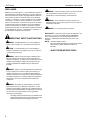
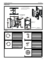
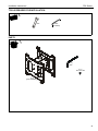
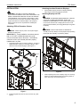
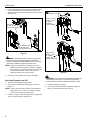
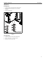
INSTALLATION INSTRUCTIONS
Large Dual Ceiling Mount
PDC Series
PDC Series
Installation Instructions
DISCLAIMER
Milestone AV Technologies, Inc., and its affiliated corporations
and subsidiaries (collectively, "Milestone"), intend to make this
manual accurate and complete. However, Milestone makes no
claim that the information contained herein covers all details,
conditions or variations, nor does it provide for every possible
contingency in connection with the installation or use of this
product. The information contained in this document is subject
to change without notice or obligation of any kind. Milestone
makes no representation of warranty, expressed or implied,
regarding the information contained herein. Milestone assumes
no responsibility for accuracy, completeness or sufficiency of
the information contained in this document.
WARNING: Use this mounting system only for its intended
use as described in these instructions. Do not use
attachments not recommended by the manufacturer.
WARNING: Never operate this mounting system if it is
damaged. Return the mounting system to a service center for
examination and repair.
WARNING: Do not use this product outdoors.
IMPORTANT ! : The PDC Series mounts are designed to be
IMPORTANT SAFETY INSTRUCTIONS
WARNING: A WARNING alerts you to the possibility of
serious injury or death if you do not follow the instructions.
mounted to a 1-1/2" NPT or NPSM following ANSI/ASME
B1.20.1 (Schedule 40, 0.154" minimum thickness steel or
aluminum - ASTM B221) threaded extension column (not
included)
NOTE: The PDC Series includes:
•
Accessory Model PDC2000 (to be used with two Listed
Chief accessory PSBU interface brackets--not
included).
CAUTION: A CAUTION alerts you to the possibility of
damage or destruction of equipment if you do not follow the
corresponding instructions.
WARNING: Failure to read, thoroughly understand, and
follow all instructions can result in serious personal injury,
damage to equipment, or voiding of factory warranty! It is the
installer’s responsibility to make sure all components are
properly assembled and installed using the instructions
provided.
WARNING: Failure to provide adequate structural strength
for this component can result in serious personal injury or
damage to equipment! It is the installer’s responsibility to
make sure the structure to which this component is attached
can support five times the combined weight of all equipment.
Reinforce the structure as required before installing the
component.
WARNING: Exceeding the weight capacity can result in
serious personal injury or damage to equipment! It is the
installer’s responsibility to make sure the combined weight of
all components located between the supporting structure and
the PDC does not exceed 400 lbs (181.44 kg) [200 lbs
(90.72 kg) each faceplate].
•
2
The weight capacity of the PDC may be LIMITED to the
lowest weight capacity of any other component located
between the PDC and the supporting structure!
--SAVE THESE INSTRUCTIONS--
Installation Instructions
PDC Series
DIMENSIONS
NOTE: PSBU INTERFACE BRACKETS
NOT SHOWN. THE PSBU INTERFACE
BRACKET WILL ADD 1” IN DEPTH AND
MAY AFFECT THE LOCATION OF THE
DISPLAY ON THE MOUNT.
ON PSBU GOES HERE
1-1/2" NPSM
FACE TILTS UP 5
DOWN 25
[BOTH SIDES]
DIMENSIONS:
APPROXIMATE CENTER OF DISPLAY
INCHES
[MILLIMETERS]
LEGEND
Tighten Fastener
Hex-Head Wrench
Apretar elemento de fijación
Llave de cabeza hexagonal
Befestigungsteil festziehen
Sechskantschlüssel
Apertar fixador
Chave de cabeça sextavada
Serrare il fissaggio
Chiave esagonale
Bevestiging vastdraaien
Zeskantsleutel
Serrez les fixations
Clé à tête hexagonale
Loosen Fastener
Open-Ended Wrench
Aflojar elemento de fijación
Llave de boca
Befestigungsteil lösen
Gabelschlüssel
Desapertar fixador
Chave de bocas
Allentare il fissaggio
Chiave a punte aperte
Bevestiging losdraaien
Steeksleutel
Desserrez les fixations
Clé à fourche
Adjust
Ajustar
Einstellen
Ajustar
Regolare
Afstellen
Ajuster
3
Installation Instructions
PDC Series
TOOLS REQUIRED FOR INSTALLATION
9/16"
5/32"
(included)
PARTS
B (1)
5/32"
C (1)
5/16-18 x 3/8"
A (1)
[PDC assembly]
4
Installation Instructions
PDC Series
INSTALLATION
Attaching Interface Bracket to Displays
1.
WARNING: FAILURE TO PROVIDE ADEQUATE
STRUCTURAL STRENGTH FOR THIS COMPONENT CAN
RESULT IN SERIOUS PERSONAL INJURY OR DAMAGE
TO EQUIPMENT! It is the installer’s responsibility to make
sure the structure to which this component is attached can
support five times the combined weight of all equipment.
Reinforce the structure as required before installing the
component.
Attach PSBU interface brackets to displays following
instructions included with interface brackets.
Installing Displays on PDC
WARNING: EXCEEDING MAXIMUM WEIGHT CAPACITY
CAN LEAD TO SERIOUS PERSONAL INJURY OR
DAMAGE TO EQUIPMENT! It is the installers responsibility
to ensure the total amount of weight placed on the mount
does not exceed 400 lbs (181.44 kg) [200 lbs (90.72 kg) each
faceplate].
Attaching PDC to Extension Column
WARNING: DISPLAY MAY WEIGH IN EXCESS OF
CAUTION: Watch for pinch points. Do not place fingers
40 LBS (18.14 KG)! Always use two people and proper lifting
techniques when installing or positioning display.
between movable parts.
IMPORTANT ! : These installation instructions assume
that a 1-1/2" NPT or NPSM (Schedule 40, 0.154"
minimum thickness steel or aluminum - ASTM B221)
extension column (not included) has been properly
installed and is in place.
1.
Mounting
button
Thread the PCD mount (A) onto the existing 1-1/2" NPT or
NPSM extension column (not included) until tight, with a
minimum of four threads engaged. (See Figure 1)
2
1
(C) x 1
1
2
(A)
Display
Figure 2
1.
While supporting each side of display, align four mounting
buttons on interface bracket with four mounting holes on
PDC. (See Figure 2) and (See Figure 3)
(A)
Figure 1
2.
Install and tighten the 5/16-18 x 3/8" set screw (C). (See
Figure )
5
PDC Series
2.
Installation Instructions
Lower each display into place listening for audible "click" to
ensure recessed area of mounting buttons are properly
seated in lower area of mounting holes. (See Figure 2) and
(See Figure 3)
May remove
pin and nut and
move to lower holes
2 Remove bolt or
padlock if used
3
Pins in "Closed"
position - move
to "Open"
position to
remove display
1
2
5
A padlock or bolt
may be placed
through latch holes
Pins in "Open"
position - move
to "Closed"
position after
display is removed.
Figure 3
WARNING: IMPROPER INSTALLATION CAN LEAD TO
DISPLAY FALLING CAUSING SERIOUS PERSONAL
INJURY OR DAMAGE TO EQUIPMENT! Ensure mounting
buttons are completely engaged in mounting holes.
NOTE: Holes are provided in the faceplate for use with a
padlock or similar locking device, if desired. In addition,
the pin and nut may be removed from the upper holes
and moved to the lower holes for use as a more
permanent locking device. (See Figure )
3.
Figure 4
Connect and secure power, audio and video cables.
WARNING: EACH DISPLAY MAY WEIGH IN EXCESS OF
40 LBS EACH! Always use two people and proper lifting
techniques when installing or positioning displays on PDC.
Removing Displays from PDC
1.
Disconnect all power/audio/video cables.
2.
Remove bolt or padlock from faceplate (if used). (See
Figure 4)
NOTE: The pin may have been used as a more permanent
locking device. If so, remove nut and pin and move
from the lower holes to the upper holes.
3.
6
Pull back on flags on upper mounting holes and press pins
down into "Open" position. (See Figure 4)
4.
Carefully lift displays from PDC.
5.
Lift up on pins and place flags back against faceplate to
return it to "Closed" position. (See Figure 4)
Installation Instructions
PDC Series
Adjustments
Roll Adjustment
1.
Loosen two Nylock nuts inside the PDC. (See Figure 5)
2.
Using the slotted holes, adjust the roll, or horizontal
movement.
3.
Tighten two Nylock nuts.
4
1
x2
5
2
3
x2
x2
6
x2
(Display and faceplate
removed for clarity)
Figure 5
Pitch Adjustment
4.
Loosen two screws on side of PDC. (See Figure 5)
5.
Adjust to desired pitch, or vertical movement.
6.
Tighten the screws on side of PDC.
7
PDC Series
Installation Instructions
USA/International
Europe
Chief, a products division of
Milestone AV Technologies
8800-002607 Rev00
2014 Milestone AV Technologies
www.chiefmfg.com
05/14
Asia Pacific
A
P
F
A
P
F
A
6436 City West Parkway, Eden Prairie, MN 55344
800.582.6480 / 952.225.6000
877.894.6918 / 952.894.6918
Franklinstraat 14, 6003 DK Weert, Netherlands
+31 (0) 495 580 852
+31 (0) 495 580 845
Office No. 918 on 9/F, Shatin Galleria
18-24 Shan Mei Street
Fotan, Shatin, Hong Kong
P 852 2145 4099
F 852 2145 4477