1
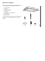
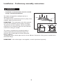
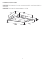
Instructions for use
Important safety instructions
4
Installation
5
Advice on safeguarding the environment
6
Troubleshooting guide
6
After-Sales Service
7
Cleaning
7
Maintenance
8
Material supplied
9
Installation - Preliminary assembly instructions
10
Installation dimensions
11
Installation - assembly instructions
12
Description and use of hood
13
Important safety instructions
YOUR SAFETY AND THAT OF OTHERS IS
VERY IMPORTANT.
This manual and the appliance itself provides
important safety messages, to be read and
observed at all times.
• The appliance is not intended for use by people
(including children) with limited physical,
sensory or mental abilities or without
experience or knowledge of it, unless they are
supervised or instructed in its use by someone
responsible for their safety.
• Do not repair or replace any part of the
appliance unless specifically indicated in the
manual.
Faulty parts must be replaced with original
ones. All other maintenance services must be
carried out by a specialised technician.
• Children must be watched over to ensure they
do not play with the appliance.
• When drilling the wall or ceiling, be careful not
to damage electrical connections and/or pipes.
• The ventilation ducts must always discharge to
the outside.
• The exhaust air must not be discharged through
a duct used to remove fumes produced by
appliances running on gas or other fuels, but
must have an independent outlet. All the
national regulations on exhausting air must be
observed.
• If the hood is used together with other
appliances operating on gas or other fuels, the
negative pressure in the room must not exceed
4 Pa (4 x 10⁻⁵ bar).
Therefore, make sure the room is adequately
ventilated.
• The Manufacturer declines any liability for
improper use or incorrect setting of the
controls.
• Regular cleaning and maintenance are essential
for correct and efficient operation of the
appliance. Frequently clean all encrustations
from dirty surfaces to prevent the accumulation
of grease. Regularly remove, clean or change
the filters.
• Failure to observe the rules for cleaning the
hood and cleaning and replacing the filters
involves the risk of fire.
• The steam extractor hood must never be
opened without the grease filters installed and
should be constantly watched over.
• Gas appliances must have pots on them when
used under the extractor hood.
• If more than three gas cooking points are used,
the hood should work at power level 2 or
higher.
This will ensure the elimination of excessive
heat in the appliance.
• Make sure the lamps are cold before touching
them.
• Do not use or leave the hood without lamps
This is the attention symbol, relevant to
safety, warning of potential risks to the user and to
others. All safety warnings are preceded by the
attention symbol and the following words:
DANGER
Indicates a hazardous situation which, if not
avoided, will cause serious injury.
WARNING
Indicates a hazardous situation which, if not
avoided, could cause serious injury.
All the safety messages specify the potential
danger/warning to which they refer and indicate
how to reduce the risk of injury, damage and
electric shock resulting from incorrect use of the
appliance.
Carefully observe the following instructions:
• Installation must be carried out at least by a
specialised technician, in compliance with the
manufacturer's instructions and the current local
safety regulations.
Do not repair or replace any part of the
appliance unless specifically indicated in the user
manual.
• The specialised technician can determine the
appropriate extractor hood exhaust air ducting
and fixing.
Fixing must be suitable for the weight of the
hood and the load.
• The appliances are designed for installation flush
with the ceiling.
• The appliance must be disconnected from the
power supply before carrying out any
installation work.
• Earthing of the appliance is compulsory. (Not
necessary for class II hoods identified by the
symbol
on the dataplate).
• The power cable must be long enough for
connecting the appliance to the power socket.
• Do not pull the power cable to unplug the
appliance.
• The electrical components must not be
accessible to the user after installation.
• Do not touch the appliance with wet parts of
the body and do not use it when barefoot.
4
correctly installed - risk of electric shock.
• Wear work gloves for all installation and
maintenance operations.
• The product is not suitable for outdoor use.
• When the hob is in use, the accessible parts of
the hood can become hot.
• For further information on the treatment,
recovery and recycling of this appliance, contact
the competent local authority, the household
waste collection service or the shop where you
purchased the appliance.
KEEP THESE INSTRUCTIONS
Disposal of electrical appliances
• This appliance is manufactured with recyclable
or reusable materials. Scrap it in accordance
with the local waste disposal regulations. Before
scrapping, make it unusable by cutting off the
power cable.
Installation
After unpacking the appliance, check for any
damage caused during transport. In case of
problems, contact the dealer or the After-Sales
Service. To avoid possible damage, it is advisable to
remove the appliance from the polystyrene base
only before installation.
seen on removing the grease filter.
The power cable ((H05 VV-F type) must only be
replaced by qualified personnel. Contact an
authorised Service Centre.
If provided with a plug, connect the appliance to a
socket complying with the current regulations and
located in an accessible area. If it does not have a
plug (direct connection to the power supply) or if
the socket is not in an accessible place, fit an
approved double-pole switch that ensures
complete disconnection from the power supply in
category III overvoltage conditions, complying with
the installation rules.
PREPARATION FOR INSTALLATION
WARNING
Very heavy product; hood handling and
installation must be carried out by at least
three people.
GENERAL RECOMMENDATIONS
Before use
Remove cardboard protection pieces, protective
film and stickers from accessories.
Make sure the hood has not been damaged during
transport.
The distance between the support surface of the
cooking device and the lowest part of the hood
must not be less than 100 cm, irrespective of the
type of hob (electric, vitroceramic, induction or
gas).
The following nominal power stresses (kW) must
not be exceeded above the gas cooking points:
During use
Do not expose the appliance to atmospheric
agents.
Max. power of a single cooking point: 4.2 kW.
Max. power of hob: 16.2 kW.
Before installation, also check the distances
specified in the hob manual.
If the cooking device installation instructions specify
a greater distance, this distance must be taken into
account.
CONNECTION TO THE POWER SUPPLY
Make sure the voltage specified on the product's
dataplate is the same as the mains voltage. The
dataplate is located inside the hood, and can be
5
Advice on safeguarding the environment
- By ensuring the correct scrapping of this
product, the user can help prevent potentially
negative consequences for the environment and
the health of people.
Packing disposal
The packing materials are 100% recyclable and are
marked with the recycling symbol (
). The
various parts of the packing must not be dispersed
in the environment, but disposed of in compliance
with the local regulations.
- The symbol
on the product or on the
accompanying documentation indicates that it
should not be treated as domestic waste but
must be taken to an appropriate collection
centre for the recycling of electrical and
electronic equipment.
Product disposal
- This appliance is marked in compliance with
European Directive 2002/96/EC on Waste
Electrical and Electronic Equipment (WEEE).
Troubleshooting guide
The hood does not work
Make sure:
• There is not a power outage.
• A certain speed is actually selected.
The hood does not extract sufficiently:
Make sure:
• The selected speed is sufficient for the amount of fumes and steam present.
• The kitchen is adequately ventilated to allow an air inlet.
• The air exhaust tube is free of obstructions.
The hood stops during operation
Make sure:
• There is not a power outage.
• The differential thermal-magnetic switch (Safety Cutout) has not tripped.
The light does not work
• Check if the lamp needs replacing.
• Make sure the lamp is correctly fitted.
The remote control does not work
• Check if the batteries need replacing.
• Make sure the lithium batteries are correctly fitted.
6
After-Sales Service
Before contacting the After-Sales Service:
1. See if you can eliminate the problem on your
own by consulting the "Troubleshooting guide".
2. Switch the hood off and then on again to check
if the problem has been eliminated.
If the following faults occur, contact the After-Sales
Service immediately:
• The hood makes strange noises and you are
unable to detect any fault in it;
• The motor runs unevenly, or strange noises can
be heard, or it is faulty;
• Switching does not work regularly.
• The Service number (the number after the
word SERVICE on the dataplate inside the
appliance). The Service number is also given in
the warranty booklet;
• Your full address;
• Your telephone number.
If any repairs are needed, contact an authorised
Service Centre (to ensure that only original spare
parts are used and that repairs are carried out
correctly).
If the problem persists after carrying out the
above checks, contact the nearest After-Sales
Service.
Always specify:
• A brief description of the fault;
• The type of appliance and exact model;
Cleaning
• Use specific detergents to clean the appliance
and follow the manufacturer's instructions.
• The remote control must only be cleaned with
a damp cloth.
WARNING
• Do not use steam cleaners.
• Disconnect the appliance from the power
supply.
IMPORTANT: Failure to observe the instructions
for cleaning the hood and replacing the filters
involves the risk of fire. Therefore make sure to
follow the instructions.
The manufacturer declines any liability for damage
to the motor, fires caused by inadequate
maintenance or failure to comply with the above
instructions.
IMPORTANT: Do not use corrosive or abrasive
detergents. If any of these products comes into
contact with the appliance, clean it immediately
with a damp cloth.
• Clean the surfaces with a damp cloth. If very
dirty, add a few drops of washing up detergent
to the water. Dry with a dry cloth.
IMPORTANT: Do not use abrasive sponges, or
metallic scrapers or scouring pads. Their use could
eventually spoil the enamelled surfaces.
7
Maintenance
WARNING
• Use protective gloves.
• Disconnect the appliance from the power supply.
GREASE FILTER
Its purpose is to retain the particles of grease produced
by cooking.
It must be cleaned every 14 days or after 15 hours of
operation, when the LED on the appliance signals this need.
Use gentle and non-aggressive detergents, clean it by hand or
in a dishwasher at low temperature and with a short cycle.
To be able to clean the filters, pull the hood extraction panel
downwards a little with both hands.
The extraction panel is released and, by means of the
cylindrical actuator, gradually turned downwards, allowing
removing of the grease filters fixed to the main body of the
hood.
After washing, refit the grease filters and lower the extraction
panel in its original position of normal operation.
IMPORTANT: Avoid temperatures above 65°C during washing.
IMPORTANT: The manufacturer declines any liability for colour alterations due to the use of aggressive
detergents.
LIGHTING SYSTEM
WARNING
• Use protective gloves.
• Disconnect the appliance from the power supply.
IMPORTANT: Make sure the lamps are cold before touching
them.
To replace the lamps, proceed as follows:
1. Pull the hood extraction panel downwards a little with
both hands. The extraction panel is released and, by means
of the cylindrical actuator, gradually turned downwards,
allowing access to the lamps.
2. Remove the glass protection cover with the aid of a
screwdriver.
3. Remove the burnt-out lamp and replace it with one having
the same characteristics: Halogen type G4 21520 (12 V 35 Watt).
4. After replacing the lamp, refit the glass cover (snap-on).
8
Material supplied
Remove all the parts from the packets and make sure
all the components listed below are included.
•
•
•
•
•
•
•
•
4+4 Plugs Ø10
4 washers
4 Threaded sleeves
4+4 Screws M8
4+4 Nuts
1 Threaded rod: length 100 cm
Flange Ø20 cm
Remote control
The material for the external motor, included in the
previous list, is supplied separately in the motor
packing.
9
Installation - Preliminary assembly instructions
WARNING
• Installation and maintenance must be carried
out by a specialised technician.
The hood is designed for installation and use in
"Extractor Version".
The hood must be installed away from very dirty areas,
windows, doors and heat sources.
IMPORTANT: The hood comes with all the material
necessary for installation on the majority of ceilings.
To guarantee correct installation, contact a qualified
technician or an architect to make sure the materials
used for the ceiling are suitable.
The steam is removed to the outside through an
exhaust pipe fixed to the connection flange. The
diameter of the hood body and motor connection
flange is 200 mm.
The diameter of the exhaust pipe must be at least 200 mm. Provide for a fixing system suitable for the
connection flange.
IMPORTANT: If the exhaust pipe is not supplied, it must be purchased separately.
10
Installation dimensions
IMPORTANT: For the operation of this hood, it is necessary to install the external motor included in a
separate pack.
IMPORTANT: For gas hobs, the maximum total power is 16.2 kW.
11
Installation - assembly instructions
WARNING
• Installation and maintenance must be carried out by a specialised technician.
• Very heavy product; hood handling and installation must be carried out by at least two
people.
The instructions below, in numerical order, refer to the drawings (giving the same numbering) in the
"Installation instructions" manual.
1. Position the external motor and fix it using the material supplied.
IMPORTANT: The external motor must be protected against atmospheric agents and can be positioned
anywhere in the house, and not necessarily in the kitchen. The maximum recommended length of the
exhaust pipe connecting the motor to the hood is 6 m. In case of elbows in the path established for the
evacuation pipe, it is advisable to position the motor more than 1 m from them so as not to negatively
affect motor efficiency.
2. Arrange the installation template (supplied) on the ceiling and drill the ceiling as indicated. The
extractor hood must be positioned centrally with respect to the hob.
IMPORTANT: Provide a socket for the electrical connection in an accessible place for hood connection.
3. Remove the glass as shown in the figure and remove the grease filters.
IMPORTANT: Provide a suitable support surface on which to place the hood in order to carry out this
operation.
4. Place the template on the ceiling: Mark the positions of the holes for fixing to the ceiling according to
the four points provided on the template.
5. Make the Ø10 holes with a suitable drill and insert the plugs supplied (A) flush with the ceiling. Screw
the screws (supplied) in the plugs so that they protrude approx. 20 mm from the ceiling (B).
6. Before hanging the hood on the ceiling, make sure the direction of the air outlet connection coincides
with the guide arranged for the exhaust duct, then screw the connection flange and covering sheet to
the hood body.
IMPORTANT: The exhaust air connection can be arranged on any of the side surfaces of the motor case
body.
To modify the outlet connection direction: if already fitted, undo the fixing screws of the connection flange
and the covering sheet and invert the position.
7. Arrange the flexible tube and connect the 200 mm flange to the tube
8. Fix the hood to the ceiling using the washers and nuts supplied.
IMPORTANT: In case of flush ceiling mounting, hang the hood on the screws (A).
IMPORTANT: In case of suspended hood fixing, screw the threaded sleeves (supplied) on the screws (C).
Cut the threaded rod (supplied) to the required length and screw it on the threaded sleeves (B).
9. Connect the hood to the suction tube connected to the external motor. Carry out the electrical
connection. Connect the external motor to the hood with the connection cable.
IMPORTANT: The exhaust air path must be prepared in such a way that the extractor hood can be easily
connected. The flexible air exhaust tube must be positioned without bends.
10. Refit the grease filters and rehook the glass as shown in the figure.
12
Description and use of hood
1.
2.
3.
4.
5.
6.
7.
8.
9.
Hood body
Extraction panel
Cylindrical actuator
Switch
IR sensor
Lighting
Grease filters
LED indicators
Anchoring to ceiling.
The hood functions and the external motor performance can be controlled in two alternative ways by
means of the remote control or the switch on the main body of the hood.
Operation using the remote control
The 2010 remote control model has six control buttons.
• Button 1:
Switches the hood on or off. When the hood is switched on, the external
motor is set to extraction power 1.
• Button 2:
Increases the extraction power (1→2→3).
The speed is displayed by lighting up of the LED of the corresponding
speed.
Button 2 has no effect on hood deactivation/activation.
• Button 3:
Decreases the extraction power (3→2→1).
The speed is displayed by lighting up of the LED of the corresponding
speed.
Button 3 has no effect on hood deactivation/activation.
• Button 4:
Activates timed hood deactivation. This function provides for a speed
decrease from power level 3 to level 1, maintained for 15 minutes before
the hood switches off. During timed operation, the corresponding LED
blinks.
• Button 5:
Increases the extraction power to maximum, and then automatically
returns to power level 3 after 5 minutes.
The speed is displayed by lighting up of the LED of the corresponding
speed.
• Button 6:
Switches the light on or off. The light intensity becomes adjustable by
keeping Button 6 pressed longer.
13
• Battery Compartment:
The battery compartment is located in the back of the remote control.
Only use CR2032 3V lithium batteries.
Replacing the batteries: the battery compartment cover is located on the back of the remote control.
Lift it with thumb and forefinger until separating the magnetic contact keeping the cover closed.
Remove the old batteries and replace them with new ones of the same type, then refit the cover.
IMPORTANT: The maximum operating range of the remote control is 5 m.
Operation by means of switch (located on the hood, under the extraction panel)
• Switch to LEFT: switches the light on or off.
• Switch to RIGHT:
1. Increases or decreases the external motor extraction power according to the sequence:
OFF→1→2→3→2→1.
2. Keep it pressed for 3 seconds to switch the hood off.
Grease Filter saturation signalling
Every 15 hours of use or after 14 days the hood signals the need to service the grease filters. The signalling
is displayed by lighting up of the corresponding red LED on the main body of the hood.
Grease filter signalling reset: after servicing the grease filters as described in the "Maintenance" section,
keep the switch under the hood extraction panel pressed to the RIGHT for 5 seconds until the red LED
goes off.
LED display (on the main body of the hood)
Hood operation status is signalled by LEDs on the appliance.
1.
2.
3.
4.
5.
6.
ON/OFF – Gradual stop
Level 1
Level 2
Level 3
Intense level
Filter saturation display
Green LED
Green LED
Green LED
Green LED
Green LED
Red LED
• LED 1:
Display of hood operation status: ON / OFF.
LED 1 blinks if the hood timed deactivation function is activated.
• LED 2:
Motor LOW power, power level 1.
• LED 3:
Motor MEDIUM power, power level 2.
• LED 4:
Motor HIGH power, power level 3.
• LED 5:
Motor MAXIMUM power.
The motor automatically returns to power level 3 after 5 minutes.
• LED 6:
Grease filter saturation indicator.
14
Printed in Italy
06/11
5019 718 02046
n
GB