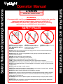
1
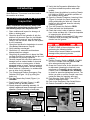
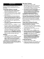
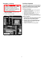
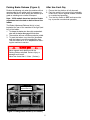
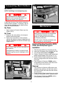
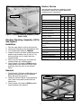
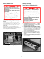
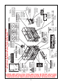
Safety Rules and Operating Instructions X-Series SERIAL NO. 13600 to Current WARNING All personnel shall carefully read, understand and follow all safety rules, operating instructions and the Scaffold Industry Associations MANUAL OF RESPONSIBILITIES (ANSI A92.6-1999) before operating or performing maintenance on any UpRight aerial work platform. SAFETY RULES NEVER operate the machine within ten feet of power lines. THIS MACHINE IS NOT INSULATED. NEVER elevate the platform or drive the machine while elevated unless the machine is on firm level surface. NEVER sit, stand or climb on guardrail or midrail. NEVER operate the machine without first surveying the work area for surface hazards such as holes, drop-offs, bumps and debris. NEVER operate the machine if all guardrails are not properly in place and secured with all fasteners properly torqued. SECURE and lock gate after mounting platform. NEVER use ladders or scaffolding on the platform. NEVER attach overhanging loads or increase platform size. LOOK up, down and around for overhead obstructions and electrical conductors. DISTRIBUTE all loads evenly on the platform. See the back cover for maximum platform load. NEVER use damaged equipment. (Contact UpRight for instructions. See toll-free phone number on back cover.) NEVER change operating or safety systems. INSPECT the machine thoroughly for cracked welds, loose hardware, hydraulic leaks, damaged control cable, loose wire connections and wheel bolts. NEVER climb down elevating assembly with the platform elevated. NEVER perform service on machine while platform is elevated without blocking elevating assembly. NEVER recharge batteries near sparks or open flame; batteries that are being charged emit highly explosive hydrogen gas. AFTER USE secure the work platform against unauthorized use by turning key switch off and removing key. NEVER replace any component or part with anything other than original UpRight replacement parts without the manufacturers consent. 1 Safety Rules and Operating Instructions Operator Manual 13. Verify that the Depression Mechanism Supports have rotated into position under each module. 14. Partially lower the platform by pushing Chassis Lift Switch to DOWN, and check operation of the audible lowering alarm. 15. Open the Chassis Emergency Lowering Valve (Figure 3) to check for proper operation by pulling and holding the knob out. Once the platform is fully lowered, close the valve by releasing the knob. 16. Turn the Chassis Key Switch to DECK. 17. Close and latch the module doors. 18. Check that route is clear of persons, obstructions, holes and drop-offs, is level and capable of supporting the wheel loads. 19. Unhook Controller from guardrail. Firmly grasp Controller while performing the following checks from the ground. Introduction This manual covers all models of the X-Series Work Platforms. This manual must be stored on the machine at all times. Pre-Operation and Safety Inspection Read, understand and follow all safety rules and operating instructions and then perform the following steps each day before use. 1. Open modules and inspect for damage, oil leaks or missing parts. 2. Check the level of the hydraulic oil with the platform fully lowered. Open the Left Module and remove the reservoir cap, oil should be visible in the filler screen. Add ISO #46 hydraulic oil if necessary. 3. Check that fluid level in the batteries is correct (See Battery Maintenance, Page 8). 4. Verify batteries are charged. 5. Check that A.C. extension cord has been disconnected from charger. 6. Check that all guardrails are in place, the Slide out Deck Extension is secured with the pin and all fasteners are properly tightened. 7. Carefully inspect the entire work platform for damage such as cracked welds or structural members, loose or missing parts, oil leaks, damaged cables or hoses, loose connections damaged or missing labels, and tire damage. 8. Move machine, if necessary, to unobstructed area to allow for full elevation. 9. Turn Chassis and Platform Emergency Stop Switches ON (Figure 1 & 2) by pulling the button out. 10. Turn the Chassis Key Switch (Figure 1) to CHASSIS. 11. Push Chassis Lift Switch (Figure 1) to UP position and fully elevate platform. 12. Visually inspect the elevating assembly, lift cylinder, cables and hoses for damage or erratic operation. Check for missing or loose parts. Control Fuse Key Switch STAND CLEAR of the work platform while performing the following checks. Protect control console cable from possible damage while performing checks. 20. Pull Emergency Stop Button out to the ON position. 21. Position Function Switch to DRIVE. For 20W, 26, and 31 models, use both HI and LOW drive when performing step 22. 22. Grasp the Control Lever so the Interlock Lever is depressed (releasing the Interlock Lever cuts power to Controller), slowly position the Control Lever to FORWARD then REVERSE to check for speed and directional control. The farther you push or pull the Control Lever from center the faster the machine will travel. 23. Push Steering Switch RIGHT then LEFT to check for steering function. 24. Push in the Emergency Stop Switch Button. 25. Rehook Controller on side guardrail. Interlock Lever Chassis Lift Switch Control Lever Hourmeter (Optional) Pot Hole Protection Support Chassis Emergency Stop Switch Steering Switch Function Switch Emergency Stop Switch Figure 2: Controller Figure 1: Chassis, Left Side 2 Elevating Platform Operation 1. Position Function Switch to LIFT. 2. While holding the Control Lever so that the Interlock Lever is depressed, push Control Lever forward to UP, the farther you push the Control Lever the faster the Platform will elevate. 3. If the machine is not level an Alarm will sound and the machine will not lift or drive. If an Alarm sounds, immediately lower the Platform and move the machine to a level location before attempting to re-elevate the Platform. Before operating work platform ensure that preoperation and safety inspection has been completed and any discrepancies have been corrected. Travel With Platform Lowered 1. Check that route is clear of people, obstructions, holes and drop-offs, is level and is capable of supporting wheel loads. 2. Verify Chassis Key Switch is turned to DECK and Chassis Emergency Stop Switch is ON, pull button out. 3. After mounting platform, lower top rail across entrance and secure entryway closure. Check that guardrails are properly assembled, in position, and that the Slide Out Deck Extension is secured with pin. Attach Controller to left or right guardrail. 4. Check clearances above, below and to the sides of platform. 5. Pull Controller Emergency Stop Button out to ON position. In case of emergency, push down to stop all functions. 6. Position Function Switch to DRIVE. For 20W, 26, and 31 models: position Function Switch to HI for traveling on level ground, LOW when extra torque is required for climbing ramps. 7. Grasp the Control Lever so the Interlock Lever is depressed (releasing the Interlock Lever cuts power to Controller), slowly push or pull the Control Lever to FORWARD or REVERSE position to travel in the desired direction. The farther you push or pull the Control Lever from center the faster the machine will travel. Depression Mechanism System When the platform is elevated, the depression mechanism system will automatically deploy. The depression mechanism system will retract automatically when the platform is lowered, and high speed drive is engaged. Be aware that while the depression mechanism system is deployed, minimum ground clearance is reduced to 3/4 inches. Travel With Platform Elevated NOTE: Work platform will travel at reduced speed when platform is elevated. 1. Check that route is clear of persons, obstructions, holes and drop-offs, is level and capable of supporting the wheel loads. 2. Check clearances above, below and to the sides of platform. 3. Position Function Switch to DRIVE position. 4. Grasp the Control Lever so the Interlock Lever is depressed (releasing the Interlock Lever cuts power to Controller), push Control Lever to FORWARD or REVERSE for desired direction of travel. 5. If the machine is not level an Alarm will sound and the machine will not lift or drive. If an Alarm sounds, immediately lower the Platform and move the machine to a level location before attempting to re-elevate the Platform. Steering 1. Position Function Switch to DRIVE. 2. While holding the Control Lever so that the Interlock Lever is depressed, push the Steering Switch to RIGHT or LEFT to turn wheels in the desired direction. Observe the tires while maneuvering the work platform to ensure proper direction. NOTE: Steering is not self-centering. Wheels must be returned to straight ahead position by operating Steering Switch. Lowering Platform 1. Position Function Switch to LIFT. 2. Grasp the Control Lever so the Interlock Lever is depressed, pull back on the Control Lever. A warning alarm will sound when lowering. 3 Emergency Lowering Fold Down Guardrails This procedure applies only to the X31N model for the purpose of passing through a standard double doorway. Guardrails must be returned to proper position before operating the work platform. If the platform should fail to lower, NEVER climb down the elevating assembly. Ask a person on the ground to open the Emergency Lowering Valve located at the rear of the machine (Figure 3). Fold Down Procedure 1. Unhook the controller from the side guardrail and place on the platform. 2. Unpin the front and rear upper rails from the side rails and rotate inwards. 3. Starting with the rollout deck rails and then the outer rails, lift up on each guardrail and fold inward. 1. Open the Emergency Lowering Valve by pulling on the handle. 2. To close, release the handle. Erection Procedure X31N Model 1. Starting with the outer rails and then the rollout deck rails, raise each guardrail and drop it down securing it in the vertical position. 2. Rotate the front and rear upper rails outward and secure them to the opposite side rails using the retaining pins. 3. Hang the controller on the side guardrail. X20N, X20W, and X26N Models Figure 3: Emergency Lowering Valve Handle 4 Parking Brake Release (Figure 4) After Use Each Day Perform the following only when the machine will not operate under its own power and it is necessary to move the machine or when towing the machine up a grade or winching onto a trailer to transport. 1. Ensure that the platform is fully lowered. 2. Park the machine on level ground, preferably under cover, secure against vandals, children or unauthorized operation. 3. Turn the Key Switch to OFF and remove the key to prevent unauthorized operation. Note: X31N models have two identical brake adjustment nuts located on both sides of the ladder. The Brake Adjustment/Release Nut(s) is (are) located at the rear of the machine to the right (and left) of the ladder. 1. To release the brakes turn the nut(s) counterclockwise until the brakes disengage from the tires. 2. The machine will now roll when pushed or pulled. 3. To reset the brakes, turn the nut(s) clockwise until the brakes have fully engaged the tires. Test the brakes on a 23 % slope before returning the machine to service. Never operate work platform with the Parking Brakes released. Serious injury or damage could result. Never tow faster than 1 ft./sec. (.3m/sec.). Parking Brake Adjustment Nuts Figure 4: Parking Brake Release (X31N Shown) 5 Transporting Work Platform Front Lifting Points By Forklift NOTE: Forklifting is for transporting only. See specifications for weight of work platform and be certain that forklift is of adequate capacity to lift platform. Front Tie Down Forklift from the rear of the machine using the forklift pockets provided. If necessary, the machine may be forklifted from the side by lifting under the Chassis Modules. Figure 6: Front Tie Downs, Lifting Lugs Maintenance By Crane 1. Secure straps to Chassis Lifting Lugs only (Figure 5 & 6). By Truck Never perform service on the work platform in the Elevating Assembly area while platform is elevated without first blocking the Elevating Assembly. 1. Maneuver the work platform into transport position and chock wheels. 2. Secure the work platform to the transport vehicle with chains or straps of adequate load capacity attached to the chassis tie down lugs (Figure 5 & 6). DO NOT stand in Elevating Assembly area while installing or removing brace. Blocking Elevating Assembly (X20N, X20W, and X26N) See Figure 7 Front tie down lugs are not to be used to lift work platform. Installation 1. 2. 3. 4. Park the work platform on firm level ground. Verify both Emergency Stop Switches are ON. Turn Chassis Key Switch to CHASSIS. Position Chassis Lift Switch to UP and elevate platform approximately nine (9) feet (2.7 m). 5. Rotate Scissors Brace towards the front and allow it to hang vertical over the lower scissor pivot tube. 6. Push Chassis Lift Switch to DOWN position and gradually lower platform until brace rests on lower scissor arm pivot tube. Overtightening of chains or straps through tie down lugs may result in damage to work platform. Removal 1. Push Chassis Lift Switch to UP position and gradually raise platform until the lower end of the Scissors Brace will clear the lower scissor arm pivot tube. 2. Rotate Scissors Brace towards the rear so that it rests on the cylinder mount, stowed position. 3. Push Chassis Lift Switch to DOWN position and completely lower platform. Rear Tie Down / Lifting Points Forklift Pockets Figure 5: Parking Brake Release, Rear Tie Downs 6 Routine Service Use the following table as a guide for routine maintenance, refer to the Service Manual for complete service instructions. SERVICE OPERATION Scissors Brace Clean entire work platform Check battery fluid level Charge batteries Check tires for damage Check lug nuts/bolts Check hydraulic fluid level Check for peeling, faded or missing labels & replace Check deck and guardrail fasteners for proper torque Inspect elevating assembly for bends or cracking Check for & repair collision damage Check emergency lowering valve operation Check electric motor brushes Check pivot pin bolts for proper torque Change hydraulic filter Check all fasteners for proper torque Change hydraulic fluid Grease front spindle bearings Grease pot hole protection cylinder rod end bearing Figure 7: Blocking Elevating Assembly (X20N, X20W, X26N) Blocking Elevating Assembly (X31N) See Figure 8 Installation 1. 2. 3. 4. Park the work platform on firm level ground. Verify both Emergency Stop Switches are ON. Turn Chassis Key Switch to CHASSIS. Position Chassis Lift Switch to UP and elevate platform approximately nine (9) feet (2.7 m), leaving enough room to freely rotate the Scissors Brace. 5. Pull out on the retaining pin and rotate the Scissors Brace into vertical position. 6. Push Chassis Lift Switch to DOWN position and gradually lower platform until the upper and lower pivot pins rest on the Scissors Brace. INTERVAL Monthly 6 Months 2 Years Daily or or or 50 Hrs. 250 Hrs. 1000 Hrs. X X X X X X X X X X X X X X X X X X Removal 1. Push Chassis Lift Switch to UP position and gradually raise platform until the Scissors Brace will clear the pivot pins. 2. Rotate the Scissors Brace counterclockwise until it locks into position parallel with the scissor arm. 3. Push Chassis Lift Switch to DOWN position and completely lower platform. Scissors Brace Retaining Pin Figure 8: Blocking Elevating Assembly (X31N) 7 Battery Maintenance Battery Charging Charge batteries at end of each work shift or sooner if batteries have been discharged. Hazard of explosive gas mixture. Keep sparks, flame and smoking materials away from batteries. Charge batteries in a well ventilated area. Always wear safety glasses when working with batteries. Do not charge batteries when the work platform is in an area containing sparks or flames. Battery fluid is highly corrosive. Rinse away any spilled fluid thoroughly with clean water. Permanent damage to batteries will result if batteries are not immediately recharged after discharging. Always replace batteries with UpRight batteries or manufacturer approved replacements weighing 62 lbs. each. Never leave charger operating unattended for more than two days. Never disconnect cables from batteries when charger is operating. Check battery fluid level daily (Figure 7), especially if work platform is being used in a warm, dry climate. If electrolyte level is lower than 3/8 in. above plates add distilled water only. DO NOT use tap water with high mineral content it will shorten battery life. Keep terminals and tops of batteries clean. Refer to the Service Manual to extend battery life and for complete service instructions. Keep charger dry. 1. Check battery fluid level (Figure 7). If electrolyte level is lower than 3/8 in. (10 mm) above plates add distilled water only. 2. Connect extension cord (12 gauge (1.5 mm²) conductor minimum and 50 ft. (15 m) in length maximum) to the charger outlet plug located at the rear of the machine. Connect other end of extension cord to properly grounded outlet of proper voltage and frequency. 3. Charger turns on automatically after a short delay, the ammeter will indicate DC charging current. 4. Charger turns off automatically when batteries are fully charged. Battery Charger Ammeter Charger Plug (Behind Guard) Figure 7: Battery Charger Figure 8: Battery Module 8 X-SERIES LABEL INSTALLATION: THESE LABELS SHALL BE PRESENT AND IN GOOD CONDITION BEFORE OPERATING THE WORK PLATFORM. BE SURE TO READ, UNDERSTAND AND FOLLOW THESE LABELS WHEN OPERATING THE WORK PLATFORM. 9 005221-000 1-REQUIRED 062562-001 1-REQUIRED 066556-001 4-REQUIRED 066552-000 1-REQUIRED 066553-000 2-REQUIRED 066560-011 (20N) 066560-010 (20W, 26N, 31N) 1-REQUIRED 066554-000 1-REQUIRED 060197-000 1-REQUIRED 066561-000 1-REQUIRED (X20N, X20W, X26N) 010076-001 1-REQUIRED 066561-002 1-REQUIRED (X31N) 066555-000 1-REQUIRED 066556-000 1-REQUIRED 101251-000 1-REQUIRED Note: Labels can be ordered by using Part Number located by each label. For machines equipped with options consult Service Manual. 066522-000 1-REQUIRED 101252-003 (20N) 101252-004 (20W) 101252-005 (26N) 101252-006 (31N) 1-REQUIRED MAXIMUM WHEEL LOAD 1400 LBS. 066559-000 1-REQUIRED 061205-005 1-REQUIRED 014222-009-99 2-REQUIRED 066558-000 1-REQUIRED 99 061220-002 1-REQUIRED 101250-002 (20N) 101250-003 (20W) 101250-004(26N) 0101250-005(31N) 2-REQUIRED 066550-000 1-REQUIRED NOTES: 10 NOTES: 11 ITEM Platform Size w/ Extension Max. Platform Capacity Standard w/ Extension on Extension Max. No. of occupants Standard on Extension Height Working Height Max. Platform Height Min. Platform Height Dimensions Weight Overall Width Overall Height Overall Length Driveable Height Surface Speed Platform Lowered Platform Raised Energy Source X20N X20W X26N X31N 28 in. x 87 in. [711 mm x 2.21 m] 44 in. x 87 in. [1.12 m x 2.21 m] 44 in. x 87 in. [1.12 m x 2.21 m] 44 in. x 87 in. [1.12 m x 2.21 m] Inside Toeboards Inside Toeboards Inside Toeboards Inside Toeboards 750 lbs. [340 kg] 250 lbs. [110 kg] 1000 lbs. [453 kg] 250 lbs. [110 kg] 1000 lbs. [453 kg] 250 lbs. [110 kg] 700 lbs. [318 kg] 250 lbs. [110 kg] 3 people 1 person 4 people 1 person 4 people 1 person 3 people 1 person 26 ft. [7.9 m] 20 ft. [6.1 m] 38 in. [.97 m] 26 ft. [7.9 m] 20 ft. [6.1 m] 39 in. [.99 m] 32 ft. [9.75 m] 26 ft. [7.92 m] 43 in. [1.09 m] 37 ft. [11.28 m] 31 ft. [9.44 m] 43 in. [1.09 m] 3,828 lbs. [1656 kg] 32 1/2 in. [.83m] 78 in. [1.98m] 92 in. [2.34m] 20 ft. [6.1 m] 4,273 lbs. [1858 kg] 48 in. [1.22 m] 79 in. [2.0 m] 92 in. [2.34 m] 20 ft. [6.1 m] 4,747 lbs. [2072 kg] 48 in. [1.22 m] 83 in. [2.11 m] 92 in. [2.34 m] 26 ft. [7.93 m] 5430 lbs. [2463 kg] 48 in. [1.22 m] 83 in. [2.11 m] 92 in. [2.34 m] 31 ft. [7.93 m] 0 to 2.3 mph [0 to 3.70 km/h] 0 to .7 mph [0 to 1.13 km/h] 24 Volt Battery Pack (4-220 Amp Hour, 6 Volt Batteries, min. wt. 62 lbs. each [28.12 kg]), 4 HP DC Electric Motor 24 Volt DC 25 AMP, 60 Hz 110 VAC 25% for 8 Hours 4 Gallons [15.2 l] 0 to 2.3 mph [0 to 3.70 km/h] 0 to .7 mph [0 to 1.13 km/h] 24 Volt Battery Pack (4-220 Amp Hour, 6 Volt Batteries, min. wt. 62 lbs. each [28.12 kg]), 4 HP DC Electric Motor 24 Volt DC 25 AMP, 60 Hz 110 VAC 25% for 8 Hours 4 Gallons [15.2 l] 0 to 2.3 mph [0 to 3.70 km/h] 0 to .7 mph [0 to 1.13 km/h] 24 Volt Battery Pack (4-220 Amp Hour, 6 Volt Batteries, min. wt. 62 lbs. each [28.12 kg]), 4 HP DC Electric Motor 24 Volt DC 25 AMP, 60 Hz 110 VAC 25% for 8 Hours 5 Gallons [19 l] 2600 psi [179 Bar] Three stage scissor assembly actuated by one Single Stage Lift Cylinder Smooth one hand joystick with two speed operation Dual Front Wheel Hydraulic Motors with series or parallel operation 15 in. [381 mm] Diameter Solid Rubber, non-marking Spring Applied, Hydraulic Release Brake with Manual Release 8 in. [254 mm] Inside 23% [13 degrees] 74 3/4 in. [1.9 m] 40 in. [1.02 m] 6 in. [152 mm] High 2600 psi [179 Bar] Four stage scissor assembly actuated by one Single Stage Lift Cylinder Smooth one hand joystick with two speed operation Dual Front Wheel Hydraulic Motors with series or parallel operation 15 in. [381 mm] Diameter Solid Rubber, non-marking Spring Applied, Hydraulic Release Brake with Manual Release 8 in. [254 mm] Inside 22% [12 degrees] 74 3/4 in. [1.9 m] 40 in. [1.02 m] 6 in. [152 mm] High 2000 psi [138 Bar] Five stage scissor assembly actuated by two Single Stage Lift Cylinders Smooth one hand joystick with two speed operation Dual Front Wheel Hydraulic Motors with series or parallel operation 15 in. [381 mm] Diameter Solid Rubber, non-marking Spring Applied, Hydraulic Release Brake with Manual Release 8 in. [254 mm] Inside 20% [11 degrees] 74 3/4 in. [1.9 m] 40 in. [1.02 m] 6 in. [152 mm] High 0 to 2.3 mph [0 to 3.70 km/h] 0 to .7 mph [0 to 1.13 km/h] 24 Volt Battery Pack (4-220 Amp Hour, 6 Volt Batteries, min. wt. 62 lbs. each [28.12 kg]), 4 HP DC Electric Motor System Voltage 24 Volt DC Battery Charger 25 AMP, 60 Hz 110 VAC Battery Duty Cycle 25% for 8 Hours Hydraulic Tank Capacity 4 Gallons [15.2 l] Maximum Hydraulic System Pressure 2400 psi [165 Bar] Lift System Three stage scissor assembly actuated by one Single Stage Lift Cylinder Control System Smooth one hand joystick with two speed operation Dual Front Wheel Hydraulic Motors Drive System with series operation Tires 15 in. [381 mm] Diameter Solid Rubber, non-marking Parking Brake Spring Applied, Hydraulic Release Brake with Manual Release Turning Radius 8 in. [254 mm] Inside Maximum Gradeability 23% [13 degrees] Wheel Base 74 3/4 in. [1.9 m] Guardrails 40 in. [1.02 m] Toeboard 6 in. [152 mm] High * Specifications subject to change without notice. Hot weather orheavy use may reduce performance. Meets or exceeds all applicable requirements of OSHA and ANSI A92.6-1999 Refer to Service Manual for complete parts and service information. FOR MORE INFORMATION Local Distributor: USA TEL: (1) 800-926-5438 or (1) 559-662-3900 FAX: (1) 559-673-6184 Parts FAX: (1) 800-669-9884 801 South Pine Street Madera, California 93637 http://www.upright.com Europe TEL: +353 1 620 9300 FAX: +353 1 620 9301 UNIT S1, PARK WEST INDUSTRIAL PARK FRIEL AVENUE NANGOR ROAD DUBLIN 12, IRELAND 12 060572-003 06-02 Safety Rules and Operating Instructions Safety Rules and Operating Instructions Specifications*