1
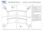
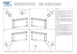
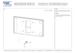
70” Smart Screen Hoister
Mounting instructions - Installatie instructies
062.7300
English
1. Please note: the stand should be installed by qualified technicians. Remove the split-lid from the flightcase.
2. Take the base plate out of the flightcase. Position the base on
the desired position.
3. Take the bottom columns with the cable duct closed out of the
flightcase and lower them gradually over the alignment pins on
the base.
4. Make sure that the end stop (a) is located at the back side of the
stand. The cable duct should be directed to the centre of the
base plate. Open the cable duct door and use the latch (b) to
secure the columns to the base.
5. Place the second column according to point 4.
6. Take the motor unit from the flightcase and lower it (as shown)
carefully over the columns until it reaches the end stops. Please
note: make sure that the pulleys and guide blocks slide through
the t-slots of the columns.
7. Place the top column (cable duct closed) over the pin of the
lower column. Make sure that the cable ducts (top and bottom)
are aligned. Use the latch (C) to secure the top columns.
8. Place the hoist set gently on top of the columns, in a way that
the cylinder and the alignment pins slide in the columns. Secure
the hoist set to the columns with the latches, located at the top
of the columns.
9. Connect the power plug with a 230V extension cord (D), not
included. Use the control switch with the red emergency stop to
bring the hoist sling to the pulley of the hoist set (with arrow
down button).
A
Nederlands
B
C
D
SmartMetals Mounting Solutions B.V. • Handelsweg 4 • 4231 EZ Meerkerk •The Netherlands •
T +31(0)183-352942 • F +31(0)183-352909 • E [email protected] • W www.SmartMetals.eu
1.Het statief dient door gekwalificeerd personeel te worden opgebouwd.
Haal de twee deksels van de flightcase af.
2. Til de voetplaat aan de handgrepen uit de flightcase. Positioneer
de voetplaat op de gewenste positie.
3. Til de onderste zuil(en) met de afsluitklep gesloten uit de flightcase en positioneer ze geleidelijk over de uitlijnpinnen van de
voetplaat.
4. Zorg er voor dat de eindaanslag (A) zich aan de achterzijde van
de voetplaat bevind. Tevens dat de afsluitklep naar het midden
van de voetplaat gericht is. Open de klep en vergrendel de
onderste zuil met behulp van de overslagsluiting (B).
Let op!! Bij demontage overslagsluiting ontgrendelen en afsluitklep sluiten alvorens de zuil eraf te tillen!!
5. Plaats ook de tweede zuil volgens punt 4.
6. Til de motorunit uit de flightcase en laat deze (als weergegeven)
voorzichtig over de zuilen zakken tot op de eindaanslagen. Let
er op dat de geleiderollen en -blokken in de T-gleuven van de
zuilen vallen.
7. Plaats de boven zuil (afsluitklep gesloten) voorzichtig over de
pin van de onderste zuil. Zorg er voor dat de afsluitkleppen
(onder en boven)met elkaar uitgelijnd zijn. Vergrendel de boven
zuil met behulp van de overslagsluiting (C).
8. Plaats de hijs set voorzichtig bovenop de zuilen, zodanig dat de
cilinder en de uitlijnpennen in de zuilen vallen. Vergrendel
de hijs set aan de zuilen met behulp van de overslagsluitingen,
die zich bovenin de zuilen bevinden.
9. Sluit de stekker met randaarde aan op 230V verlengsnoer (D)
Gebruik de bedieningsschakelaar met rode noodstop om de
hijsband naar de katrol van de hijs set te brengen (met pijltje
naar beneden)
MOUNTING SOLUTIONS
70” Smart Screen Hoister
Mounting instructions - Installatie instructies
062.7300
English
10.Lead the hoist hook from the rear to the front of the stand
through the pulley (E) as shown. Lower the hook further down
into the motor unit.
11. Check if the hoist sling is not twisted. Hook the hoist sling to
the motor unit. Do not forget to secure the hook!
12.Position the flightcase so that the screen bracket is aligned with
the coupling bolts and the key holes in the motor unit.
13.Adjust the height of the end stops, so that the coupling bolts of
the screen bracket are aligned with the largest opening of the
keyholes in the motor unit (with the screen still in the flightcase).
Please note: this applies to first installation or a change in screen
size only!
14.Use the control switch with the red emergency stop, to hook on
the screen from within the flightcase. Note that the coupling bolts
are located below the screen fall prevention.
15.Pull the index plunger (located at the underside of motor-unit)
to stop securing, to rotate the screen from landscape to portrait.
Make sure the plunger falls back into locking position. Where
required, use the height adjustment (H) to level the screen.
16.Bring the flightcase carefully towards the stand, so that it is
positioned right underneath the screen (shown at point 12).
Afterwards lower the screen, release the screen’s fall protection (I)
by moving the lever to the right just before the screen reaches
the bottom of the flightcase, then continue to lower the screen
until it reaches the bottom.
E
F
Nederlands
G
I
SmartMetals Mounting Solutions B.V. • Handelsweg 4 • 4231 EZ Meerkerk •The Netherlands •
T +31(0)183-352942 • F +31(0)183-352909 • E [email protected] • W www.SmartMetals.eu
H
10.Geleid de hijshaak vanaf de achterkant naar de voorkant van
het statief door de katrol (E) zoals weergegeven. Laat de
hijshaak vervolgens zakken tot in de motorunit.
11. Controleer of de hijsband niet verdraaid is. Haak vervolgens de
hijsband aan de motorunit, vergeet de hijshaak niet te borgen!
12.Breng de flightcase voorzichtig naar het statief toe zodanig dat
de koppelbussen (F) van de schermbracket uitgelijnd zijn met
de sleutelgaten van de motorunit.
13.Pas de hoogte van de eindaanslagen zodanig aan, dat de koppelbussen van de schermbracket zich op dezelfde hoogte bevinden als de grootste opening van de sleutelgaten in de motorunit
(met het scherm nog in de flightcase). Let op: dit is alleen van
toepassing bij een eerste gebruik of wanneer er een ander
formaat scherm toegepast gaat worden.
14.Gebruik de bedieningsschakelaar met rode noodstop om het
scherm vanuit de flightcase aan te haken. Let er op dat de koppelbussen zich onder de scherm valbeveiliging bevinden! Is dat het
geval dan pas het scherm op de gewenste hoogte brengen!
15.Trek de arreteerpen uit (die zich aan de onderzijde van de motorunit bevind) om de beveiliging te ontgrendelen en het scherm
van landscape naar portrait te draaien. Let op: dat deze nadien
in zijn beveiliging valt. Gebruik de hoogteverstelling (H) om het
scherm waterpas te stellen.
16.Breng de flightcase voorzichtig naar het statief toe, zodanig dat
deze zich recht onder het scherm bevind (zie punt 12). Laat het
scherm zakken en ontgrendel de valbeveiliging (I) door het
hendeltje naar rechts te verplaatsen, vlak voordat het scherm de
bodem van de flightcase raakt, en laat vervolgens de het scherm
verder zakken tot de bodem bereikt is.
MOUNTING SOLUTIONS