1
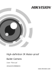
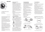
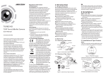
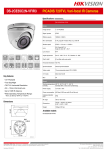
Regulatory Information
FCC Information
User Manual
FCC compliance: This equipment has been tested
and found to comply with the limits for a digital
device, pursuant to part 15 of the FCC Rules.
These limits are designed to provide reasonable
protection against harmful interference when the
equipment is operated in a commercial
environment. This equipment generates, uses,
and can radiate radio frequency energy and, if
not installed and used in accordance with the
instruction manual, may cause harmful
interference to radio communications. Operation
of this equipment in a residential area is likely to
cause harmful interference in which case the user
will be required to correct the interference at his
own expense.
UD.6L0201D1104A01
FCC Conditions
Bullet Camera
www.hikvision.com
Thank you for purchasing our product. If there
are any questions, or requests, please do not
hesitate to contact the dealer.
This manual applies to
Type
Model
Ⅰ
DS-2CE1512P(N)-IR, DS-2CE1582P(N)-IR
DS-2CE15A2P(N)-IR,DS-2CE15C2P(N)-IR
DS-2CE1582P(N)-IRP,DS-2CE15A2P(N)-IRP
Ⅱ
DS-2CE1682P(N)-IT1, DS-2CE16A2P(N)-IT1
DS-2CE16C2P(N)-IT1, DS-2CE1682P(N)-IT3
DS-2CE16A2P(N)-IT3,DS-2CE16C2P(N)-IT3
Ⅲ
DS-2CE1682P(N)-IT5, DS-2CE16A2P(N)-IT5
DS-2CE16C2P(N)-IT5
Ⅳ
DS-2CE1582P(N)-VFIR3,DS-2CE15A2P(N)-VFIR3
DS-2CE15C2P(N)-VFIR3
This manual may contain several technical
incorrect places or printing errors, and the
content is subject to change without notice.
The updates will be added to the new version of
this manual. We will readily improve or update
the products or procedures described in the
manual.
0200001030603
This device complies with part 15 of the FCC
Rules. Operation is subject to the following two
conditions:
1. This device may not cause harmful
interference.
2. This device must accept any interference
received, including interference that may
cause undesired operation.
EU Conformity Statement
This product and - if applicable the supplied accessories too are
marked with "CE" and comply
therefore with the applicable harmonized
European standards listed under the Low Voltage
Directive 2006/95/EC, the EMC Directive 2004/
108/EC, the RoHS Directive 2011/65/EU.
2012/19/EC (WEEE directive):
Products marked with this symbol
cannot be disposed of as unsorted
municipal waste in the European
Union. For proper recycling, return
this product to your local supplier
upon the purchase of equivalent new equipment,
or dispose of it at designated collection points.
For more information see:www.recyclethis.info.
2006/66/EC (battery directive):
This product contains a battery
that cannot be disposed of as
unsorted municipal waste in the
European Union.
See the product documentation for specific
battery information. The battery is marked with
this symbol, which may include lettering to
indicate cadmium (Cd), lead (Pb), or mercury (Hg).
For proper recycling, return the battery to your
supplier or to a designated collection point. For
more information see: www.recyclethis.info.
Sun Shield Adjustable Screw
Power Cable
Lens
Video Cable
IR LED
Figure 1-2 Overview of Type Ⅱ Camera
Sun Shield
Adjustable Screw
Power Cable
Lens
Video Cable
IR LED
Figure 1-3 Overview of Type Ⅲ Camera
Video Cable
Mounting Base
1 Introduction
1.1 Product Features
This series of camera adopts new generation
sensor with high sensitivity and advanced
circuit design technology. It features high
resolution, low image distortion and low noise
features, etc., which makes it suitable for
surveillance system and image processing
system.
●High-performance sensor and high resolution
bring high-quality image
●IR LED enables the day/night surveillance
Power Cable
Sun Shield
Lens
IR LED
Figure 1-4 Overview of Type Ⅳ Camera
2 Installation
Before you start:
●Make sure that all the related equipment is
power-off during the installation.
●IR cut filter auto switch
●ATW brings high color rendition
●Check the specification of the products for the
●Ingress protection:IP66
installation environment.
●Check whether the power supply is matched
1.2 Overview
Video Cable
Mounting Base
with your AC outlet to avoid damage.
●If the product does not function properly, please
contact your dealer or the nearest service
center. Do not disassemble the camera for
Sun Shield
Lens
IR LED
Power Cable
repair or maintenance by yourself.
●Please make sure that the ceiling or the wall
is strong enough to withstand 3 times the
Figure 1-1 Overview of Type Ⅰ Camera
weight of the camera.
2.1 Ceiling Mounting for Type I
Camera
2.2 W all Mounting for Type II / II I
Camera
Steps:
Steps:
1.Drill the screw holes and the cable hole in the
ceiling according to the supplied drill template.
2.Hammer the supplied plastic expansion bolt into
the screw holes.
1.Drill the screw holes and the cable hole in the
ceiling according to the drill template.
2.Hammer the supplied plastic expansion bolt into
the screw holes.
2.3 Ceiling Mounting for Type IV
Camera
1
90°
Steps:
1.Drill the screws holes and the cable hole on the
ceiling according to the supplied drill template.
2.Hammer the supplied plastic expansion bolt
into the screw holes.
2
3
360°
360°
2
1
Ceiling Mounting
1
2
Figure 2-9 3-axis Adjustment
2
No.2 Screw Hole
for Mounting
Base 1
No.1 Screw Hole
for Bracket
1
2
Figure 2-1 Drill Template
3.Route the cables to the cable hole and connect
the corresponding power cable and video cable.
4.Fix the camera to the ceiling with the supplied
screws.
Figure 2-4 Drill Template
3.Route the cables to the cable hole and connect
the corresponding power cable and video cable
4.Fix the camera to the wall with the supplied
screws.
Adjusting Screw
Figure 2-7 Drill Template
3.Route the cables to the cable hole and connect
the corresponding cables.
4.Fix the camera to the ceiling with the supplied
screws.
6.Adjust the zoom and the focus.
1).Output the image to the monitor.
2).Push forward to remove the adjusting sheet
located on the bottom of the camera. See
figure below.
3).Insert the removed adjusting sheet to zoom
slot and focus slot to adjust the zoom and the
focus.
4).Put the adjusting sheet back after the
adjustment is done.
Focus
Zoom
Figure 2-2 Fix the Camera to the Ceiling
5.Adjust the surveillance angle.
1).Loosen No.3 adjusting screw to adjust the
panning position (0° ~ 360°) .
2).Tighten No.3 adjusting screw.
3).Loosen the No.2 adjusting screw to adjust the
tilting position (0° ~ 90°).
4).Tighten No.2 adjusting screw.
5).Loosen No.1 adjusting screw to adjust the
azimuth angle of the image (0° ~ 360°).
6).Tighten No.1 adjusting screw.
Figure 2-5 Fix the Camera to the Wall
Adjusting Sheet
5. Adjust the surveillance angle.
1). Loosen No.3 adjusting screw to adjust the pan
2.4 Power Supply
position ( 0° ~ 360°) .
2).Tighten No.3 adjusting screw.
3). Loosen No.2 adjusting screw to adjust the
tilting position( 0° ~ 90°).
4).Tighten No.2 adjusting screw.
5). Loosen No.1 adjusting screw to adjust the
rotation position (0° ~ 360°) .
6).Tighten No.1 adjusting screw.
3
90°
360°
Figure 2-8 Fix the Camera to the Ceiling
5.Adjust the surveillance angle.
1).Loosen No.3 adjusting screw to adjust the
panning position (0°~ 360°).
2).Tighten No.3 adjusting screw.
3).Loosen No.2 adjusting screw to adjust the
360°
Figure 2-3 3-axis Adjustment
Figure 2-10 Focus and Zoom Adjustment
1
Figure 2-6 3-axis Adjustment
2
tilting position (0° ~ 90°).
4).Tighten No.2 adjusting screw.
5).Loosen No.1 adjusting screw to adjust the
azimuth angle of the image (0° ~ 360°).
6).Tighten No.1 adjusting screw.
Figure 2-11 The Powe Cable & the Video Cable
Note:
Please make sure that the power adapter is
compatible with the camera, and the standard
power supply is 12V DC. Please refer to the
technical specification for more information.