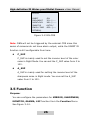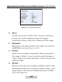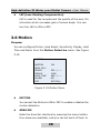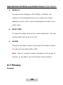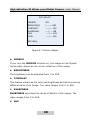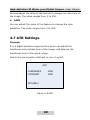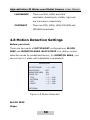
1
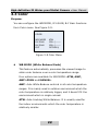
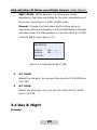
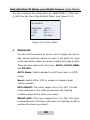
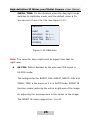
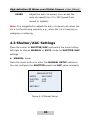
High-definition IR Water-proof Bullet Camera User Manual UD.6L0201D0086A01 High-definition IR Water-proof Bullet Camera· User Manual Thank you for purchasing our product. If there are any questions, or requests, please do not hesitate to contact the dealer. This manual applies to DS-2CE1582P (N)-VFIR3 DS-2CC1283P-VFIR3 DS-2CC1283P-AVFIR3 DS-2CC1281P (N)-VFIR3 DS-2CC1281P (N)-AVFIR3 DS-2CC12A1P (N)-VFIR3 DS-2CC12A1P (N)-AVFIR3 This manual may contain several technical incorrect places or printing errors, and the content is subject to change without notice. The updates will be added to the new version of this manual. We will readily improve or update the products or procedures described in the manual. DISCLAIMER STATEMENT “Underwriters Laboratories Inc. (“UL”) has not tested the performance or reliability of the security or signaling aspects of this product. UL has only tested for fire, shock or casualty hazards as outlined in UL’s Standard(s) for Safety, UL60950-1. UL Certification does not cover the performance or reliability of the security or signaling aspects of this product. UL MAKES NO REPRESENTATIONS, WARRANTIES OR CERTIFICATIONS WHATSOEVER REGARDING THE PERFORMANCE OR RELIABILITY OF ANY SECURITY OR SIGNALING RELATED FUNCTIONS OF THIS PRODUCT.” 0100001030320 1 High-definition IR Water-proof Bullet Camera· User Manual Regulatory Information FCC Information FCC compliance: This equipment has been tested and found to comply with the limits for a digital device, pursuant to part 15 of the FCC Rules. These limits are designed to provide reasonable protection against harmful interference when the equipment is operated in a commercial environment. This equipment generates, uses, and can radiate radio frequency energy and, if not installed and used in accordance with the instruction manual, may cause harmful interference to radio communications. Operation of this equipment in a residential area is likely to cause harmful interference in which case the user will be required to correct the interference at his own expense. FCC Conditions This device complies w ith part 15 of the FCC Rules. Operation is subject to the following two conditions: 1. This device may not cause harmful interference. 2. This device must accept any interference received, including interference that may cause undesired operation. EU Conformity Statement This product and - if applicable - the supplied accessories too are marked with "CE" and comply therefore with the applicable harmonized European standards listed under the Low Voltage Directive 2006/95/EC, the EMC Directive 2004/108/EC. 2 High-definition IR Water-proof Bullet Camera· User Manual 2002/96/EC (WEEE directive): Products marked with this symbol cannot be disposed of as unsorted municipal waste in the European Union. For proper recycling, return this product to your local supplier upon the purchase of equivalent new equipment, or dispose of it at designated collection points. For more information see: www.recyclethis.info. 2006/66/EC (battery directive): This product contains a battery that cannot be disposed of as unsorted municipal waste in the European Union. See the product documentation for specific battery information. The battery is marked w ith this symbol, which may include lettering to indicate cadmium (Cd), lead (Pb), or mercury (Hg). For proper recycling, return the battery to your supplier or to a designated collection point. For more information see: www.recyclethis.info 3 High-definition IR Water-proof Bullet Camera· User Manual Table of Contents 1 Introduction ........................................................................6 1.1 Product Features ...................................................... 6 1.2 Overview ................................................................. 7 2 Installation..........................................................................8 2.1 Ceiling Mounting ...................................................... 8 2.2 Power Supply ......................................................... 12 3 Menu Description (A) .......................................................14 3.1 Menu Overview ...................................................... 14 3.2 Exposure................................................................ 15 3.3 Color...................................................................... 22 3.4 Day & Night ........................................................... 23 3.5 Function................................................................. 26 3.6 Motion ................................................................... 28 3.7 Privacy................................................................... 30 3.8 Setup..................................................................... 33 3.9 System .................................................................. 36 3.10 Exit ...................................................................... 37 4 Menu Description (B) .......................................................38 4.1 Main Menu ............................................................. 38 4.2 Lens Settings ......................................................... 39 4.3 Shutter/AGC Settings ............................................. 41 4.4 White Balance Settings........................................... 43 4.5 Backlight Settings .................................................. 47 4.6 Picture Adjust Settings ........................................... 47 4.7 ATR Settings .......................................................... 49 4.8 Motion Detection Settings ....................................... 50 4.9 Privacy Mask Settings............................................. 52 4 High-definition IR Water-proof Bullet Camera· User Manual 4.10 Day/Night Settings ............................................... 53 4.11 NR Settings .......................................................... 56 4.12 Camera ID Settings .............................................. 56 4.13 SYNC Settings ...................................................... 58 4.14 Language Settings................................................ 59 4.15 Camera Reset Settings ......................................... 59 4.16 Pixel Correct Settings ........................................... 59 4.17 Save All/Exit ........................................................ 60 5 High-definition IR Water-proof Bullet Camera· User Manual 1 Introduction 1.1 Product Features This camera adopts a high-sensitivity sensor and advanced circuit design technology. It possesses features of high resolution, low image distortion and low noise, which are suitable for surveillance system and image processing system. Adopt high-performance sensor, and w ith a high resolution which brings high-quality images. High co lor rendition with Auto White Balance function. High S/N ratio which makes the image is vivid and clear. Support Auto Electronic Shutter control to adapt to different environments. Support auto gain control to adapt to changing light conditions. Support Backlight Compensation (BLC), which can adjust the iris so that the object in the sensitive area is properly exposed. Bullet camera adopts an advanced product design and the mounts of them support wiring out from inside. Adopt unique two-shell design which can ensure the senor has a proper temperature to get a high quality image. Ingress Protection level reaches IP66. 6 High-definition IR Water-proof Bullet Camera· User Manual 1.2 Overview Bracket Mounting Base Power Cable Video Cable Zoom Figure 1-1 Overview 7 Focus High-definition IR Water-proof Bullet Camera· User Manual 2 Installation Before you start: Read the following contents carefully before the installation. Make sure that all the related equipment is power-off during the installation. Check the specification of the products for the installation environment. Check whether the power supply is matched w ith your AC outlet to avoid damage. If the product does not function properly, please contact your dealer or the nearest service center. Do not disassemble the camera for repair or maintenance by yourself. Ceiling mounting is recommended, we will take ceiling mounting as an example to explain the installation steps in this chapter. 2.1 Ceiling Mounting Notes: 1. When mounting the camera, for the cement wall, you need to mount the base with expansion screws. For the wooden wall, you need to mount the base with self-tapping screws. 2. Please ensure that the wall is strong enough to withstand more than 3 times the weight of the camera and the bracket. If the wall is not strong enough, the camera may fall and cause serious damage. 8 High-definition IR Water-proof Bullet Camera· User Manual 3. Before any operation, please make sure that the device in the package is in good condition and all the assembly parts are completed. Steps: 1. Drill the holes on the wall with the supplied drilling template. 2. Route the cables inside the ceiling or on the surface. If you want to route the cables inside the ceiling, drill the cable hole in the ceiling for wiring; pull all cables through the ho le and terminate all wires (if not yet terminated). 3. Connect the power cable and video cable and secure the mounting base w ith camera to the wall with supplied screws. Wall Figure 2-1 Secure the Camera 4. Three-axis adjustment. 1). Preview the image of the camera on a monitor. 9 High-definition IR Water-proof Bullet Camera· User Manual Note: You must loosen the lock screw or fixed ring before adjustment and tighten it when you adjusted it. 2). Rotate the panning table to adjust the panning position of the camera. The adjustable range is from 0 degree to 360 degrees. 3). Rotate the tilting table to adjust the tilting position of the camera. The adjustable range is from 0 degree to 75 degrees. 4). Rotate the lens to adjust the azimuth angle of the image. The adjustable range is from 0 degree to 360 degrees. Pan: 0~360° Lock screw Tilt: 0~90° Lock screw Rotation: 0~360° Figure 2-2 Adjust the Azimuth Angle 5. To focus and zoom, adjust the FOCUS and ZOOM screws on the camera to get a clear image. 10 High-definition IR Water-proof Bullet Camera· User Manual Zoom Focus Figure 2-3 Adjust the Lens 11 High-definition IR Water-proof Bullet Camera· User Manual 2.2 Power Supply Figure 2-4 Power Cable (Round Interface) Note: Please make sure the power adapter is match with the camera, the standard adapter model for camera is DC12V (Please refer to technical specifications for more details). 12 High-definition IR Water-proof Bullet Camera· User Manual Figure 2-5 Power Cable (Two-needle Interface ) Note: Please make sure that the power adapter is match with the camera. The standard power supply of the camera is usually 12V DC or 24V AC (Please refer to technical specifications for more details). 13 High-definition IR Water-proof Bullet Camera· User Manual 3 Menu Description (A) Note: This Menu only works for DS-2CC1283P-VFIR3, and DS-2CC1283P-AVFIR3. 3.1 Menu Overview This series of camera supports OSD menu, the main menu is listed as below: Table 3-1 Main Menu Main EXPOSURE LENS, HBLC/D-WDR, AGC, 3D-DNR, SENSE UP COLOR WB MODE, R-Y GAIN, B-Y GAIN DAY &NIGHT DAY&NIGHT MODE, A_SUP, C_SUP FUNCTION MIRROR, SHARPNESS, MONITOR, GAMMA,LSC MOTION MOTION, AREA SEL, SENSITI, DISPLAY, HOLD TIME, ALARM. PRIVACY MASK1~MASK8 SETUP TITLE, MANUAL DPC, AUTO DPC, OLPF, OSD COLOR SYSTEM CAMERA ID, COMMUNI, LANGUAGE EXIT FACTORY SET, SAVE&EXIT, EXIT Menu 14 High-definition IR Water-proof Bullet Camera· User Manual 3.2 Exposure Purpose: Exposure is realized by Shutter/IRS/Gain control. On the Exposure menu, you can configure the LENS, HBLC/D-WDR, AGC, 3D DNR, SENSE-UP settings. See Figure 3-1. EXPOSURE LENS HBLC/D-WDR AGC 3D DNR SENSE-UP EXIT ELC BLC HIGH AUTO AUTO RETURN↓ Figure 3-1 Exposure Menu Lens You can set the Lens to ELC mode or DC mode. ELC Mode In the ELC Mode, auto shutter has a higher priority to auto iris. E.SHUTTER value can be configured to AUTO(default), x2, x4, x8, x16, x32, x64, x128, x256, x512, x1024,1/50, 1/100, 1/120FLK, 1/250, 1/500, 1/1K,1/2K, 1/4K, 1/10K and 1/100K (second). BRIGHT refers to the brightness of the image, in ELC mode, the image brightness is controlled by shutter. You can set 15 High-definition IR Water-proof Bullet Camera· User Manual the value from 1 to 100. 50 is the default value. See Figure 3-2. LENS-ELC E.SHUTTER AUTO BRIGHT 028 ---|---RETURN↓ Figure 3-2 ELC Mode DC Mode In DC Mode, auto iris has a higher priority to auto shutter. AUTO, x2, x4, x8, x16, x32, x64, x128, x256, x512, x1024,1/50, 1/100, 1/120FLK, 1/250, 1/500, 1/1K, 1/2K, 1/4K,1/10K,1/100K (second) are selectable for E.SHUTTER. BRIGHT of the image is controlled by iris in DC mode, and the value can be set from 1 to 100. DC REF means the reference value of the iris. The bigger the value you set, the higher the brightness reference value is. You can set the value from 0 to 20. See Figure 3-3. 16 High-definition IR Water-proof Bullet Camera· User Manual LENS-DC E.SHUTTER AUTO BRIGHT 028---|----DC REF 010---|----RETURN↓ Figure 3-3 DC Mode HBLC/D-WDR Note: This item contains BLC, HLI, and D-WDR function. BLC (Backlight Compensation) If there’s a strong backlight, the object in the foreground appears silhouetted or dark. BLC can correct the exposure of the subject. BLC supports AUTO mode and Manual mode. In the Auto mode, the areas are not configurable, and in the manual mode, you can set the area size and coordinate by changing the value of its up/down/left/right. See Figure 3-4 and Figure 3-5. BLC level can be adjusted by WEIGHT in the BLC menu; you can set it to OFF, LOW, MID, and HIGH. 17 High-definition IR Water-proof Bullet Camera· User Manual BLC BLC MODE BLC WEIGHT RETURN ↓ MANUAL MID Figure 3-4 BLC BLC-MANUAL TOP BOTTOM LEFT RIGHT RETURN↓ 006--|------012----|----004-|-------011---|------ Figure 3-5 BLC Area Set HLI (Highlight Inverse) Highlight inverse is a function which inverses the area which is strongly- highlighted. The HLI BLC mode is controlled by BLC window area (HBLC). You can set the inverse area by changing the value of its top/bottom/left/ right. And you can also set the BLC level to OFF, LOW, MID, HIGH. See Figure 3-6. 18 High-definition IR Water-proof Bullet Camera· User Manual HBLC BLC LEVEL TOP BUTTOM LEFT RIGHT RETURN ↓ OFF 006 --|-------012---|-------004--|-------011---|-------- Figure 3-6 HBLC Mode ALL DAY and NIGHT are selectable. All day means HLI function will be effective for both day and night, and Night means it only takes effect in night mode. Set Level It’s the value boundary for HLI function. The HLI function will be performed if it reaches the value you set. The value can be set from 0 to 255. Gray Mode Black, Gray, and D.Gray are selectable to deal with the images which are over the value you set for HLI. See Figure 3-7. 19 High-definition IR Water-proof Bullet Camera· User Manual HLI HBLC MODE SET LEVEL GRAY MODE MASK SEL RETURN ↓ NIGHT 255---------| BLACK MASK1 Figure 3-7 HLI Mask Sel Mask Sel is for configuring some areas which you don’t want to be inversed. You can select four areas in all and define the size of the mask by changing the value for its top, bottom, left and right. See Figure 3-8. MASK1 MODE TOP BUTTOM LEFT RIGHT RETURN ↓ ON 008--|------022---|-----007--|------034----|----- Figure 3-8 Mask Set D-WDR (Digital-Wide Dynamic Range) When the Digital Wide Dynamic Range function is on, the bullet camera is able to balance the brightest and darkest sections of a scene to produce a picture that is better balanced in lighting and provides more details . 20 High-definition IR Water-proof Bullet Camera· User Manual You can set the D-WDR LEVEL from 0 to 20. The bigger the value is, the higher the D-WDR intensity is. AGC (Auto Gain Control) AGC is a control circuit that automatically changes the gain of a receiver or other piece of equipment to maintain the output video quality. Under low illuminations, AGC function can regulate the gain and amplify of the video signal. Four options are available for AGC: HIGH, MID, LOW, OFF. 3D DNR (Digital Noise Reduction) DNR is the process of removing noise from a signal. It compensates for the low-light conditions, and corrects imperfections in the image by removing a large percentage of the noises; it helps to deliver a clear signal, a more visually appealing image, and makes it easier to identify the objects. Five options are available for 3D DNR: AUTO, HIGH, MID, LOW, OFF. SENSE-UP This series of camera supports frame accumulation at maximum of 512, it will make the image brighter by multiple exposures the image and it only works in low luminance. You can set the value for sense-up to AUTO, OFF, x2, x4, x8, x16, x32, x64, x128, x256 and x512. 21 High-definition IR Water-proof Bullet Camera· User Manual 3.3 Color Purpose: You can configure the WB MODE, R-Y GAIN, B-Y Gain functions from Color menu. See Figure 3-9. COLOR WB MODE R-Y GAIN B-Y GAIN EXIT ATW 128---|------128---|------RETURN↓ Figure 3-9 Color Menu WB MODE (White Balance Mode) This feature automatically processes the viewed image to retain color balance over a color temperature range. Four options are available for WB MODE: ATW, AWC, AWC>PUSH and MANUAL. AWC: Auto White Balance controls in all color temperature ranges. It is mainly used in outdoor environment which the color temperature is relatively bigge r, and it doesn’t fit the environment which is single colored. ATW: Auto-tracking White Balance. It is usually used for the indoor environments which the color temperature is relatively smaller. 22 High-definition IR Water-proof Bullet Camera· User Manual AWC>PUSH: White balance is continuously being adjusted in real-time according to the color temperature of the scene illumination in AWC>PUSH mode. Manual: Change the Red value and the Blue value to manually set the white balance. Set the WB Mode to Manual, and then enter the Manual Menu to set the value for M.WB R and M.WB B, see Figure 3-10. WB-MANUAL M.WB R M.WB B RETURN↓ 064 - - - |- - - 064 - - - | - - - - Figure 3-10 Manual Mode of WB R-Y GAIN Adjust the red gain. You can set the value for R-Y GAIN from 0 to 255. B-Y GAIN Adjust the blue gain. You can set the value for B-Y GAIN from 0 to 255. 3.4 Day & Night Purpose: 23 High-definition IR Water-proof Bullet Camera· User Manual You can configure the parameters for D&N MODE, C_SUP, and A_SUP function from Day & Night Menu. See Figure 3-11. DAY & NIGHT D&N MODE C_SUP A_SUP EXIT AUTO 030---|------051---|------RETURN↓ Figure 3-11 Color Menu D&N MODE You can set the camera to deliver color images during the day, and as light diminishes at night, it will switch to night mode and deliver black and white images with high quality. There are four options for this item: AUTO, COLOR, B&W, and EX-CDS. AUTO Mode: D&N is decided by AGC gain level in AUTO mode. Burst: Switch ON or OFF to enable or disable signal synchronization. DAY>NIGHT: The value ranges from 0 to 255. The day mode switches to the night mode when the light ing condition reaches the value you select. NIGHT>DAY: The value ranges from 0 to 255. The night mode switches to the day mode when the lighting condition reaches the value you select. 24 High-definition IR Water-proof Bullet Camera· User Manual DWELL TIME: It’s the duration when the day/night mode switches to night/day mode, and the default value is 3s. You can set it from 0 to 15s. See Figure 3-12. D&N-AUTO BURST ON DAY>NIGHT 19--|-----NIGHT>DAY 18--|-----DWELL TIME 003--|-----RETURN↓ Figure 3-12 D&N-Auto Note: The value for day>night must be bigger than that for night>day. EX-CDS: D&N is decided by the external CDS signal in EX-CDS mode. The configuration for BURST, DAY>NIGHT, NIGHT>DAY and DWELL TIME is the same as it is in AUTO Mode. SMART IR function means reducing the entire brightness of the image for adjusting the overexposure in the center of the image. The SMART IR value ranges from 1 to 40. 25 High-definition IR Water-proof Bullet Camera· User Manual EX-CDS BURST DAY>NIGHT NIGHT>DAY SMART IR DWELL TIME RETURN↓ ON 151---|----100---|-----AUTO 003---|----- Figure 3-13 EX-CDS Note: D&N will not be triggered by the external CDS since this series of cameras do not have alarm output, while the SMART IR function is still configurable from here. C_SUP C_SUP is mainly used to set the inverse level of the color noise in Night Mode. You can set the C_SUP value from 0 to 100. A_SUP A_SUP is mainly used for sett ing the inverse level of the sharpness noise in Night mode. You can set the A_SUP value from 0 to 100. 3.5 Function Purpose: You can configure the parameters for MIRROR, SHARPNESS, MONITOR, GAMMA, LSC function from the Function Menu. See Figure 3-14. 26 High-definition IR Water-proof Bullet Camera· User Manual FUNCTION MIRROR SHARPNESS MONITOR GAMMA LSC EXIT ON 016---|---MODE 1 0.45 OFF RETURN↓ Figure 3-14 Function Menu Mirror You can turn the Mirror ON or OFF. Turning on the Mirror function can flip the displayed image 180 degrees horizontally, shown as the mirror reflection of the image. Sharpness Sharpness is the edge contrast of an image. The value for SHARPNESS can be set from 0 to 30. Monitor There are two modes are selectable: Mode 1 and mode 2. The image in Mode 1 is much smoother, and the image in Mode 2 looks more stereo perception, but the noise will be relatively bigger. Gamma Gamma is the name of a nonlinear operation used to code and decode luminance or tristimulus values in video or still image system. The value for GAMMA can be set to USER, 0.45, 0.60 and 1.00. 27 High-definition IR Water-proof Bullet Camera· User Manual LSC(Lens Shading Compensation) LSC is used for the complement the quality of the lens. It’s a function which increases gain of screen angle. You can turn the LSC to ON or OFF. 3.6 Motion Purpose: You can configure Motion, Area Select, Sensitivity, Display, Hold Time and Alarm from the Motion Detection menu. See Figure 3-15. MOTION MOTION AREA SEL SENSITI. DISPLAY HOLD TIME ALARM EXIT ON 025---|-----ICON 003---|-----ON RETUTN↓ Figure 3-15 Motion Menu MOTION You can set the Motion to ON or OFF to enable or disable the motion detection. AREA SEL Enter the Area Sel interface by pressing the menu button. Four areas are available, and you can set each of them to 28 High-definition IR Water-proof Bullet Camera· User Manual ON or OFF. You can define the Area size by selecting the different value for TOP, BUTTON, LEFT, and RIGHT. See Figure 3-16 and Figure 3-17. MOT-AREA AREA 1 AREA 2 AREA 3 AREA 4 RETURN↓ ON ON ON ON Figure 3-16 Turn on the Motion Detection AREA1 – ON TOP BOTTOM LEFT RIGHT RETURN↓ 025---|------070---|------025---|------080---|------- Figure 3-17 Set the Area Size SENSITI You can set the value for Sensitivity from 0~30. The higher the value is, the easier the alarm will be triggered. 29 High-definition IR Water-proof Bullet Camera· User Manual DISPLAY You can set the Display to OFF, ICON, or TRACE. Icon means it w ill be displayed as an icon when the motion detection occurs, and it w ill be displayed as mosaic if you select trace. HOLD TIME It means the delay time set for motion detection. You can set the Hold Time from 3s to 15s. ALARM Turing on the Alarm means it w ill support the alarm output. You can turn the Alarm ON or OFF. Note: There is no alarm output interface for this series of camera, so the Alarm will not function at the present. 3.7 Privacy Purpose: 30 High-definition IR Water-proof Bullet Camera· User Manual If you don’t want some parts of the area to be viewed or recorded, then the Privacy Mask will be useful here. You can set 8 privacy masks in all. Steps: 1. Enter the privacy configuration interface by pressing the up/down button. See Figure 3-18. PRIVACY MASK 1 MASK 2 MASK 3 MASK 4 MASK 5 MASK 6 MASK 7 MASK 8 EXIT ON ON ON ON OFF OFF OFF OFF RETURN↓ Figure 3-18 Privacy Menu 2. Select the privacy mask number and press the menu button to configure the privacy mask position, color etc. see Figure 3-19. 31 High-definition IR Water-proof Bullet Camera· User Manual MASK 1 DOT SEL DOT XY MOVE XY COLOR SET RETURN↓ L_TOP BLACK Figure 3-19 Privacy Mask Setup DOT SEL Select L_BOT, L_TOP, R_BOT, R_TOP from DOT SEL to decide which corner you will use to change the mask size and position. DOT XY Adjust the privacy mask size by pressing the left/right button. MOVE XY Adjust the privacy mask position by pressing the left/right button. COLOR SET 32 High-definition IR Water-proof Bullet Camera· User Manual Select the color for the privacy mask. Blue, Magenta, Cyan, Gray, Black, White, Red, Green are selectable. 3. Click Return to save the settings and go back to the previous page. 3.8 Setup Purpose: You can configure the TITLE, MANUAL DPC, AUTO DPC, OLPF, and OSD COLOR from SETUP menu. See Figure 3-20. SETUP TITLE MANUAL DPC AUTO DPC OLPF OSD COLOR EXIT OFF OFF AUTO 850 BLUE RETURN↓ Figure 3-20 Setup Menu Title Set the Title to ON or OFF by pressing the left/right button, and press menu button to select the user title. After 33 High-definition IR Water-proof Bullet Camera· User Manual selecting Title On, you are able to write TEXT to display on the screen. It supports at maximum of 16 characters input. ← → are used for moving the cursor to the exact position where the title should be edited or modified. POS is for changing the location of the title. You can change the title position by setting the menu button up/down/ left /right. CLR is used for deleting the title, and you can click Return to go back to the previous page. See Figure 3-21. USER TITLE ABCDEFGHIJKLMNOPQRSTUV WXYZ0123456789 !”#$%&’ ()*+, -./ ← → <=>?@[\]^_ ← → CLR POS RET “ “ “_ _ _ _)A_ _ _ Figure 3-21 User Title Manual DPC 34 High-definition IR Water-proof Bullet Camera· User Manual The camera supports Dead Pixels Compensation function. It will correct the defective pixels which are not performed as expected. You can set the Manual DPC to Manual or OFF, and if you select Manual for it, then you can enter the parameter interface to configure the parameters for White Thr (range from 0 to 255), Black Thr (range from 0 to 255), and DPC Level (range from 0 to 255). Auto DPC You can set the AUTO DPC to AUTO or OFF, and if you select Auto for it, then you can set the DPC Level (range from 0 to 50), and DPC RUN from the sub-menu. OLPF (Optical Low Pass Filter) OLPF can reduce or eliminate the color rendition effect of the infrared. The value for it can be set to 850 filter (IR-PASS) or 650 filter (IR-CUT). OSD(On Screen Display) COLOR Blue, Magenta, Cyan, Gray, Black, White, Red, Green are the selectable color for OSD. 35 High-definition IR Water-proof Bullet Camera· User Manual 3.9 System Purpose: You can set the Camera ID, Communication, and Language from this System menu. See Figure 3-22. SYSTEM CAMERA ID COMMUNI. LANGUAGE EXIT 008--|------OFF ENGLISH RETURN ↓ Figure 3-22 System Menu Camera ID Camera ID is the communication address, and it is configurable from 0 to 255. Communication OFF/ON are selectable for RS485 Communication. You can view the Protocol and Baudrate information by turning the communication ON. Language English/ Chinese Si/ Chinese Tr/ Korean/ Japanese / Italian/ Russian/ Portuguese/ Spanish/ German/ French are selectable. 36 High-definition IR Water-proof Bullet Camera· User Manual 3.10 Exit Purpose: You can save your settings and exit. And you can also restore all the parameters back to the Factory Settings. See Figure 3-23. EXIT FACTORY SET NO SAVE & EXIT↓ EXIT↓ Figure 3-23 Exit Menu Factory Set: YES or No are selectable. Selecting YES will restore all the parameters to the factory set. Save & Exit: press the menu button to save the settings and exit. Exit: press menu button to exit menu w ithout saving the new settings. 37 High-definition IR Water-proof Bullet Camera· User Manual 4 Menu Description (B) Note: This Menu works for DS-2CC1281P (N)-VFIR3, DS-2CC1281P (N)-AVFIR3, DS-2CC12A1P (N)-VFIR3, DS-2CC12A1P (N)-AVFIR3. 4.1 Main Menu Steps: 1. Press the menu button on the rear panel of the camera to access the main menu and the submenu. 2. Switch the menu button up/down to position the cursor. 3. Switch the menu button left/right to select the options. Table 4-1 Main Menu Main Menu LENS AUTO, MANUAL SHUTTER/AGC SHUT+AUTO IRIS, AUTO IRIS WHITE BAL ATW, PUSH, PUSH LOCK, USER1, USER2, ANTI CR, MANUAL BACKLIGHT BLC,HLC PICT ADJUST MIRROR, BRIGHTNESS, CONTRAST, SHARPNESS, HUE, GAIN ATR LUMINANCE, CONTRAST MOTION DET DETECT SENSE, BLOCK DISP, MONITOR 38 High-definition IR Water-proof Bullet Camera· User Manual AREA, AREA SEL PRIVACY AREA SEL, COLOR, TRANSP, MOSAIC DAY/NIGHT AUTO, COLOR, B/W NR Y LEVEL CAMERA ID SYNC INT , LINELOCK LANGUAGE English/Chinese/Japanese/French/Russian/ Portuguese/ Spanish/ German CAMERA RESET DPC EXIT/SAVE ALL 4.2 Lens Settings Purpose: On LENS settings menu and SHUTTER/AGC settings menu, you can set the value of iris, shutter speed and AGC (Auto Gain Control) manually to obtain the optimum brightness of the image, or set them to AUTO mode, which enables the parameters to adjust automatically according to the changing lighting environment. Note: If the iris, shutter speed and AGC are all in AUTO mode, in high luminance environment, auto iris is prior to auto shutter; in lower luminance, auto shutter is prior to auto iris; Auto AGC only takes effect in low luminance. Please refer to Section 4.3 for more details. 39 High-definition IR Water-proof Bullet Camera· User Manual Move the cursor to LENS, and you can switch the menu button left/right to select MANUAL or AUTO. Press the menu button to access the manual/auto interface. In MANUAL mode, you have to set the LENS IRIS value manually. In AUTO mode, press the menu button to enter the AUTO IRIS submenu. AUTO IRIS TYPE MODE SPEED DC AUTO -----|---- 080 RETURN Figure 4-1 Auto Iris TYPE Choose the Auto-iris drive type as DC type. VIDEO type is not supported. MODE Choose the iris mode. AUTO, OPEN and CLOSE are selectable. In AUTO mode, iris value adjusts automatically according to the lightning environment; iris is fully open if you choose OPEN; and iris is completely closed if you choose CLOSE. 40 High-definition IR Water-proof Bullet Camera· User Manual SPEED Adjust the auto iris speed. You can set the auto iris speed from 0 to 255 (speed from lowest to highest). Note: It is suggested to adjust the auto iris speed only when the iris is not functioning properly, e.g., when the iris is keeping on enlarging or reducing. 4.3 Shutter/AGC Settings Move the cursor to SHUTTER/AGC and switch the menu button left/right to choose MANUAL or AUTO mode for SHUTTER/AGC settings. MANUAL mode Press the menu button to enter the MANUAL SETUP submenu. You can configure the SHUTTER speed and AGC value manually. MANUAL SETUP MODE SHUT+AGC SHUTTER 1/50 AGC 6.00 RETURN Figure 4-2 Manual Setup 41 High-definition IR Water-proof Bullet Camera· User Manual SHUTTER Manually set the shutter speed. For PAL standard, 1/50, 1/120, 1/250, 1/500, 1/1K, 1/2K, 1/4K and 1/10K (second) are selectable. For NTSC standard, 1/60, 1/100, 1/250, 1/500, 1/1K, 1/2K, 1/4K and 1/10K (second) are selectable. AGC The AGC value can be set as 6.00, 12.00, 18.00, 24.00, 30.00, 36.00, 42.00 or 44.8. AUTO mode In AUTO SETUP mode, the SHUTTER and AGC value will change automatically according to the lighting environment, which can be distinguished as LOW LUMINANCE and HIGH LUMINANCE. Note: AGC is only available in LOW LUMINANCE condition. AUTO SETUP HIGH LUMINANCE MODE SHUT+AUTO IRIS/AUTO IRIS BRIGHTNESS ----|---- 080 LOW LUMINANCE MODE AGC BRIGHTNESS *0.50 RETURN Figure 4-3 Auto Setup 42 High-definition IR Water-proof Bullet Camera· User Manual HIGH LUMINANCE MODE When LENS type is AUTO IRIS, you can choose SHUT+AUTO IRIS mode or AUTO IRIS mode; When LENS type is Manual, only SHUT mode is available. BRIGHTNESS Set the desired BRIGHTNESS value which the iris and shutter speed will adjust automatically for. The value ranges from 0 to 255. Note: In SHUT+AUTO IRIS mode, AUTO IRIS is prior to AUTO SHUT. LOW LUMINANCE MODE Only AGC is available. BRIGHTNESS Set the desired BRIGHTNESS value as the target which the AGC will adjust automatically for. ×0.25, ×0.50, ×0.75 and ×1.00 are selectable. 4.4 White Balance Settings Purpose: This feature processes the image to retain color balance over a color temperature range and remove the unrealistic color casts. 43 High-definition IR Water-proof Bullet Camera· User Manual ATW, PUSH, PUSH LOCK, USER1, USER2, ANTI CR and MANUAL modes are selectable. You can switch the menu button left/right to choose the mode. PUSH In the PUSH mode, the viewed image retains color balance automatically according to the color temperature. PUSH LOCK In the PUSH LOCK mode, press the menu button to lock the white balance settings. The white balance parameters will be fixed as the current settings. ANTI CR (Anti-Color Rolling) In this mode, the system suppresses the color rolling under the fluorescent light when processing the color balance. USER 1 This mode is the indoor mode. It is suitable for indoor applications. USER 1 WB B-GAIN R-GAIN ----|----030 ----|----033 RETURN Figure 4-4 User 1 WB 44 High-definition IR Water-proof Bullet Camera· User Manual B-GAIN Adjust the blue gain. The B-GAIN value ranges from 0 to 255. R-GAIN Adjust the red gain. The R-GAIN value ranges from 0 to 255. USER 2 This mode is suitable for environments with fluorescent light. B-GAIN The B-GAIN value ranges from 0 to 255. R-GAIN The R-GAIN value ranges from 0 to 255. MANUAL In MANUAL WB mode, you can change the white balance LEVEL manually. MANUAL WB LEVEL ----|----064 RETURN Figure 4-5 Manual WB ATW(Auto-Tracking White Balance) 45 High-definition IR Water-proof Bullet Camera· User Manual In ATW mode, white balance is continuously being adjusted in real-time according to the color temperature of the scene illumination. ATW SPEED DELAY CNT ATW FRAME ENVIRONMENT ------|--239 --|------016 *1.00 INDOOR RETURN Figure 4-6 ATW SPEED The SPEED can be set from 0 to 255. DELAY CNT Set the delay time between monitoring the changing lighting conditions and adjusting the white balance. ATW FRAME Adjust the ATW image size. ×0.50, ×1.00, ×1.50 and × 2.00 are available. ENVIRONMENT INDOOR and OUTDOOR are selectable. 46 High-definition IR Water-proof Bullet Camera· User Manual 4.5 Backlight Settings Purpose: You can set the backlight compensation and high light compensation functions of the camera on BACKLIGHT settings submenu. There are OFF, BLC and HLC modes selectable. Switch the menu button left/right to choose the mode. BLC (Backlight Compensation) If there’s a strong backlight, the object in the foreground appears silhouetted or dark. BLC can correct the exposure of the subject. In this mode, normally the background is overexposed. HLC (Highlight Compensation) HLC masks strong light sources to suppress the intervening light. This function makes it possible to capture the details of the target. 4.6 Picture Adjust Settings Purpose: On PICT ADJUST submenu, you can adjust the features of MIRROR, BRIGHTNESS, CONTRAST, SHARPNESS, HUE, and GAIN. Switch the menu button left/right to choose the mode. 47 High-definition IR Water-proof Bullet Camera· User Manual PICT ADJUST MIRROR BRIGHTNESS CONTRAST SHARPNESS HUE GAIN OFF |-------- 000 ----|---- 128 ----|---- 128 ----|---- 128 ----|---- 128 RETURN↓ Figure 4-7 Picture Adjust MIRROR If you turn the MIRROR function on, the image w ill be flipped horizontally, shown as the mirror reflection of the image. BRIGHTNESS The brightness can be adjusted from 0 to 255. CONTRAST This feature enhances the color and brightness distribution among different parts of an image. The value ranges from 0 to 255. SHARPNESS SHARPNESS describes the clarity of details in the image. The value ranges from 0 to 255. HUE 48 High-definition IR Water-proof Bullet Camera· User Manual You can adjust the value of this feature to change the color tone of the image. The value ranges from 0 to 255. GAIN You can adjust the value of this feature to change the color gradation. The value ranges from 0 to 255. 4.7 ATR Settings Purpose: It is a digital dynamic range function which can adjust the brightness and contrast level of the image, and balance the brightness level of the whole image. Switch the menu button left/right to turn it on/off. ATR LUMINANCE CONTRAST LOW LOW RETURN Figure 4-8 ATR 49 High-definition IR Water-proof Bullet Camera· User Manual LUMINANCE There are MID, HIGH and LOW selectable, standing for middle, high and low luminance respectively. CONTRAST There are MID, HIGH, LOW, MIDLOW and MIDHIGH selectable. 4.8 Motion Detection Settings Before you start: There are two parts of MOTION DET configurations, BLOCK DISP and MONITOR AREA. BLOCK DISP is to define motion detection areas by predefined blocks; for MONITOR AREA, you can set up to 4 areas with adjustable coordinators. MOTION DET DETECT SENSE BLOCK DISP MONITOR AREA AREA SEL TOP BUTTOM LEFT RIGHT ----|---- 111 OFF ON 1/4 ----|---- 128 ----|---- 128 ----|---- 128 ----|---- 128 RETURN Figure 4-9 Motion Detection BLOCK DISP Steps: 50 High-definition IR Water-proof Bullet Camera· User Manual 1. Move the cursor to MOTION DET, and switch it to ON and press the menu button to enter the submenu. 2. Position the cursor on DETECT SENSE, and switch the menu button left/right to adjust the sensitivity level. 3. Position the cursor on BLOCK DISP, and switch the menu button left/right to select ENABLE. 4. Press the menu button to enter the blocking area settings interface. 5. You can press the menu button once to set a pane as a blocking area, or press it again to cancel it. 6. Press and hold the menu button for 2 seconds to return to the previous menu. 7. Select ON to enable BLOCK DISP. 8. Move the cursor to MONITOR AREA and select ON. 9. Return to the MAIN MENU and click SAVE ALL. 10. You can find the BLOCK DISP taking effect after you exit the main menu. MONITOR AREA Steps: 1. Move the cursor to MOTION DET, and select ON and press the menu button to enter the submenu. 2. Position the cursor on DETECT SENSE, and select the menu button left/right to adjust the sensitivity level. 3. Position the cursor on MONITOR AREA. Select ON to enable area motion detection. 51 High-definition IR Water-proof Bullet Camera· User Manual 4. Position the cursor on AREA SEL. You can set 4 separate monitor areas at a time. 5. Select one of the monitor areas and set the values of TOP, BOTTOM, LEFT and RIGHT to define its size and position. You can see the frame of the area shown on the screen while defining the values. 6. Return to MAIN MENU and click SAVE ALL. 7. You can find the MONITOR AREA frame taking effect after you exit the main menu. Note: The MONITOR AREA frame can only take effect when there are BLOCK DISP panes being configured. 4.9 Privacy Mask Settings Purpose: You can set privacy masks on the live view screen to cover certain areas where don’t need to be viewed or recorded. The size, color and transparency of the areas are adjustable. Steps: 1. Move the cursor to PRIVACY, set it as ON and press the button to enter PRIVACY submenu. 2. Position the cursor on AREA SEL and select one mask. 3. Set the values of TOP, BOTTOM, LEFT and RIGHT to define the size and position of the privacy mask. 4. Select the color and the transparency value for the privacy mask. Turn on MOSAIC if you want to set the mask as mosaic. 52 High-definition IR Water-proof Bullet Camera· User Manual 5. Repeat steps 1-4 to configure more privacy masks. Note: You can set up to 8 privacy masks; only 4 masks can be configured when motion detection function is on. PRIVACY AREA SEL TOP BUTTOM LEFT RIGHT COLOR TRANSP MOSAIC 1/8 ----|---- 128 ----|---- 128 ----|---- 128 ----|---- 128 1 0.00 OFF RETURN Figure 4-10 Privacy Masks AREA SEL Select a privacy area. COLOR Values 1 to 8 are selectable. TRANSP 1.0, 0.75, 0.5 and 0 are selectable. 4.10 Day/Night Settings Purpose: You can set the camera to deliver color images during the day, and as light diminishes at night, sw itch to night mode and deliver black and white images w ith high quality. There are five modes selectable: AUTO, COLOR, B/W, EXT1 and EXT2. 53 High-definition IR Water-proof Bullet Camera· User Manual COLOR Color mode is used for normal lighting conditions. B/W B/W mode can increase the sensitivity in low light ing conditions. On the B/W submenu, you can switch it to ON or OFF to enable or disable BURST. B/W BURST OFF RETURN Figure 4-11 B/W AUTO Enable the day/night modes to switch automatically. Steps: 1. Move the cursor to DAY/NIGHT, and switch the menu button left/right to select AUTO. 2. Press the menu button to enter the submenu. 54 High-definition IR Water-proof Bullet Camera· User Manual DAY/NIGHT BURST DELAY CNT DAY→NIGHT NIGHT→DAY OFF |-------- 000 -|------- 003 -|------- 005 RETURN Figure 4-12 Day/Night BURST Switch ON or OFF to enable or disable signal synchronization. DELAYCNT Set the delay time before the day/night modes switch. The value ranges from 0 to 255. DAYNIGHT The value ranges from 0 to 255. The day mode switches to the night mode when the lighting condition reaches the value you select. NIGHTDAY The value ranges from 0 to 255. The night mode switches to the day mode when the lighting condition reaches the value you select. EXT1/ EXT2 55 High-definition IR Water-proof Bullet Camera· User Manual EXIT1/EXT2 mode enables synchronization of day/night and IR light. 4.11 NR Settings Purpose: Noise Reduction is used to reduce the noises in the video signal. Move the cursor to NR, press the menu button to enter the NR submenu. NR Y LEVEL -|------- 004 RETURN Figure 4-13 NR Y LEVEL The value ranges from 0 to 15. 4.12 Camera ID Settings Purpose: On Camera ID submenu, you can customize the camera ID. You can also adjust the camera ID position on the live view screen. 56 High-definition IR Water-proof Bullet Camera· User Manual Switch the menu button to set it to ON and press the menu button to enter the submenu. CAMERA ID ABCDEFGHIJKLMNOPQRSTUV WXYZ0123456789-!”#$%&’ ()_ , ¥:;<= >?@\^*.x+/ CHR 1 CHR 2 ← → ↑ ↓ CLR POS RETURN Figure 4-14 Camera ID Customizing the camera ID Steps: 1. Switch the menu button up/down/left/right to position the cursor on the character you want to select. Note: The characters include letters, numbers and symbols. 2. Press the menu button to enter the character you selected. It will be displayed under CAMERA ID and above the character list. 3. Repeat steps 1 to 2 to select other characters. Modifying the camera ID Steps: 57 High-definition IR Water-proof Bullet Camera· User Manual 1. Position the cursor on one of the arrows. 2. Press the menu button to position the cursor on the character of the current camera ID which needs to modify. 3. Move the cursor to the character list and select one to replace it. Clearing the camera ID Steps: 1. Position the cursor on CLR. 2. Press the menu button to clear the characters. Positioning the camera ID Steps: 1. Move the cursor to POS and press the menu button to enter the position setting interface. 2. Switch the menu button up/down/left/right to position the camera ID. 3. Press the menu button to save the position and ex it. 4.13 SYNC Settings You can set the synchronization mode as internal or power (line lock) synchronization. Steps: 1. Exit the OSD menu to the live view screen. 2. Switch and hold the menu button to the right for 2 seconds. You can see the live view screen flickering for several seconds. 58 High-definition IR Water-proof Bullet Camera· User Manual 3. Press the menu button to enter the menu and you can see the SYNC mode is switched from INT to LINELOCK or vice versa. Note: For line lock synchronization, you can adjust the V Phase value to adjust the power synchronous phase. 4.14 Language Settings You can choose the language of the menu. The factory default language is English. Steps: 1. Move the cursor to LANGUAGE. 2. Switch the menu button left/right to select the language you prefer. 4.15 Camera Reset Settings Move the cursor to CAMERA RESET, press the menu button to reset all camera settings to factory default parameters. 4.16 Pixel Correct Settings Purpose: The CCD sensor of the lens may appear defective pixels. You can trigger the pixel correction function to correct and compensate the defective pixels. Steps: 59 High-definition IR Water-proof Bullet Camera· User Manual 1. Exit the OSD menu to the live view screen. 2. Switch and hold the menu button to the left for 2 seconds until you see the message of “COVER-UP LENS/CLOSE IRIS”. 3. Cover the lens or close the iris to prevent the light from entering the lens. 4. Press the menu button to confirm. You w ill be able to see the bright dot detects on the grainy screen. 5. After the process, the bright dot defects will disappear and you can see “SUCCESS” on the screen. 6. Press the menu button to exit. Note: An ERROR may happen because that the lens was not fully covered. Please repeat above steps to try again. 4.17 Save All/Exit Move the cursor to SAVE ALL to save all the settings; move the cursor to EXIT to exit the menu. 60