1
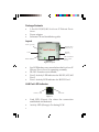
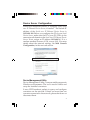
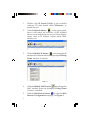
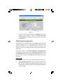
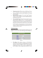
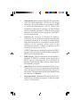
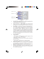
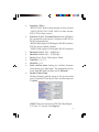
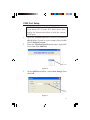
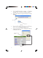
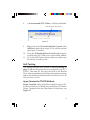
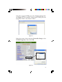
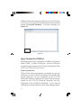
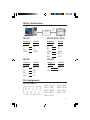
2-Port RS-232/422/485
Serial over IP Ethernet
Device Server
Installation Guide
Introduction
The 2-Port RS-232/422/485 Serial over IP Ethernet Device
Server is designed to operate serial ports over 10/100
Mbps Ethernet networks, transmitting via TCP/IP
protocol.
Features and Benefits
•
•
•
•
•
•
•
ARM Cortex-M3 32-bit high performance CPU
Auto reset on Idle detection
Easy to use Web Server Management
115.2Kbps data throughput
Power output: 12V, 500mA
Built-in 1.5KV Magnetic Isolation
15KV ESD for all signals
System Requirements
•
•
Pentium® or equivalent computer with an available
serial port and ethernet port
Windows® 8 (32-/64-bit) / 7 (32-/64-bit) / Vista
(32-/64-bit) / XP (32-/64-bit) / Server 2003 & 2008
(32/-64-bit) / Server 2008 R2 / 2000
04-0965A
1
Package Contents
•
•
•
2-Port RS-232/422/485 Serial over IP Ethernet Device
Server
Power adapter
Software CD and installation guide
Layout
DC-In (power)
RS-232/422/
485 (Port 2)
LAN
RS-232
(Port 1)
LED Indicators
(SYS, Port-2,
Port-1)
Reset Button
Figure 1: Layout
•
•
•
•
Sys: LED flashes every second when the Serial over IP
Ethernet Device Server is operating normally
DI/DO: Function not available
Port-2: Activity LED indicator for RS-232/422/485
Port 2
Port-1: Activity LED indicator for RS-232 Port 1
LAN Port LED Indicator
Activity LED
Link LED
Figure 2
•
•
2
Link LED (Green): On when the connection
established and detected
Activity LED (Orange): On during R/W
Device Server Configuration
Follow the instructions below to configure your Serial
over IP Ethernet Device Server, if needed. The default IP
address of the Serial over IP Ethernet Device Server is
192.168.0.100. Before you configure the IP of your Serial
Device Server, make sure the IP of your PC/NB is in the
same network domain as the Serial over IP Ethernet Device
Server. If not, assign an IP address 192.168.0.X.(* X is a
random number between 0-254, except 100). For more
details about the network settings, see Web Console
Configuration, in the next sub section.
Figure 3
Device Management Utility
Device Management Utility, is an executable program in
Windows environments. The tool is used to detect and
setup the installed converters.
It uses UDP broadcast packets to query and configure
converters on the network. If there are more than one
converter connected to the network, please shut down or
disconnect them.
3
1.
2.
Double click IP Search Utility in the included
software CD, then double click CVBrowser... to
enable the tool.
Click the Refresh button
on the upper panel,
then it will detect the existence of the installed
device server and the device server's latest display
status, such as IP address, subnet mask, MAC
address, etc.
Figure 4
3.
Click the Modify IP button
and change the IP
address and subnet mask from the prompted Dialog
Frame window, if needed.
Figure 5
4.
5.
4
Click the Modify MAC button
and change the
MAC address from the prompted Dialog Frame
window, if needed.
Click the Web Browse button
to open the Web
Browser Configuration webpage. See Figure 6.
Figure 6
Login
Type in password and click the Login button, then
make your changes from the Web Browser
Configuration webpage. See the section for more
information.
Web Console Configuration
In addition to basic IP address and subnet mask, specific
device settings can be set through HTTP protocol with
popular browsers, e.g. Internet Explorer, Firefox, etc.
Setup is as easy as surfing the web, no special software is
required.
You can access to the Web Browser Configuration
webpage by either clicking the Web Browse button from
the CVBrowser software, or by typing in the Serial over IP
Ethernet Device Server's IP address in the URL field of the
browser.
Login page
See Figure 6 and refer to the field descriptions below:
•
System time elapsed: the time elapsed since start of
this device in [Day:Hour:Minute:Sec] format. This
information can be useful in identifying the reliability
of the system
5
•
•
•
•
Firmware version: The Serial over IP Ethernet Device
Server's firmware version is identified by date code.
Serial number: Product serial number as provided
by the factory
Ethernet MAC address: The unique MAC (Media
Access Control) address used for identification by
the Ethernet network
Password and Login: This field is the administration
password for authentication. The factory default
setting is blank. However, it is recommended to set
a password under normal operation. If you forget
the password, the device server can be returned to
factory default setting (blank password) by pressing
in the reset button while powering on the Serial over
IP Ethernet Device Server
Controller Setup
After login, you will enter the parameter setting page. See
Figure 7 -9 and refer to the following field descriptions.
Figure 7
•
6
IP address: The default setting is 192.168.0.100.
Note that the IP address must not conflict with other
devices on your network. If DHCP client mode is
enabled and there's a DHCP server on the network,
the IP address will be assigned by the DHCP server
•
•
•
•
•
Subnet mask: Subnet mask of 255.255.255.0 is usually
used for small networks, 255.255.0.0 for larger
networks. If your IP address is provided by an ISP
or network administrator, please obtain that
information and enter it correctly. If DHCP client
mode is enabled and there's a DHCP server on the
network, this field will be assigned by the DHCP
server automatically
Gateway IP: Gateway or Router IP address.
"Gateway" is a device which connects local network
to external network. If you need to communicate
with other networks or your device owns a real IP
address on the internet, please type in the
information correctly. If there's no gateway on the
network, just leave it as 0.0.0.0.
If DHCP client mode is enabled and there's a DHCP
server on the network, this field will be assigned by
DHCP server automatically
DHCP client: DHCP client mode can be enabled/
disabled. If DHCP is enabled, there should be a
DHCP server on the network. If it is disabled, IP
address, Subnet mask, and Gateway address must
be manually assigned
Auto Reset: If the function is enabled, the Serial over
IP Ethernet Device Server would restart automatically
when the device has been disconnected and/or no
data input. The parameter can be from "0 to 255" and
the time unit is "Minute"
Login password: Administration password used to
login to the Controller Setup page. It may be empty
or up to 15 characters
7
Interface- Port 1
Baudrate - Port 1
Interface- Port 2
Baudrate- Port 2
Figure 8
•
•
•
•
•
•
8
Serial I/O Port 1 (RS-232): One RS-232 serial port for
connecting RS-232 serial device
Serial I/O Port 1 (RS-422/485): One RS-422/485
serial port for connecting RS-422/485 serial device
Local Port: A socket port assigned to the serial port.
It's a 16-bit number, ranging from 1 to 65535. Because
the numbers below 1000 are used for specific
purposes (e.g. 80 is for HTTP protocol), we suggest
you use numbers larger than 100. Generally the port
number 4660 is used for the serial communication.
However you should specify different port number
for each serial port
Socket Mode:
- TCP Server: TCP protocol, passive open, to be
connected from the TCP clients.
- TCP Client: TCP protocol, active open, connect to
the TCP server.
- UDP Client: UDP protocol, connectionless
Remote IP address: The server IP address and socket
port would be connected in TCP Server, TCP Client
and UDP Client mode for a certain serial port
Remote socket port: The server socket port would
be connected in TCP Client and UDP Client mode
for a certain serial port
•
•
•
•
•
•
•
•
•
Interface - Port 1
- RS232 GTxD, RxD for data stream, no flow control
- RS232 (RTS/CTS) GTxD, RxD for data stream,
RTS/CTS for flow control
Interface - Port 2: TheAuto Detect feature will detect
the connected serial device's interface as RS-422 or
RS-485 automatically
- RS485 (Half duplex): Half duplex RS-485 interface,
RTS for driver enable/disable
- RS422 (Full duplex): Full duplex RS-422 interface
Baudrate- Port 1: 300 ~ 460800 bps
Baudrate- Port 2: 300 ~ 115200 bps
Parity: None, Even, Odd, Space, Mark
Data Bits: 5, 6, 7, 8
Stop Bit: 1 or 2
Force off-line time: Setting for off-line duration
when there is no data input. The parameter can be
from "0 to 255" and the time unit is "Minute"
Packet Collect Time
Packet collecting period setup of the device serial
port's Tx and Rx. It can be 0 to 999, and the time unit
is "mSec"
Figure 9
NOTE: There's no function for DI/DO. Skip Digital
I/O Port 1/2 section. See Figure 9.
9
Device Server Updated
Press the Update button after you complete your changes.
The Serial over IP Ethernet Device Server will save all setting
into internal non-volatile memory and then reboot. The
Web Console webpage will refresh in around 5 seconds.
NOTE: If Controller Updated/Now restarting
doesn't show up after clicking the update button,
this means the configuration page may be left
idling too long and it timed out, so no update was
performed. Important: If the domain of the RS232/422/485 Serial over IP Ethernet is different from
that the connected PC, the login page won't appear
until the Serial Device Server's gateway address is
corrected.
Factory Default Setting
1.
Press and hold the reset button as you power on the
Serial over IP Ethernet Device Server for 3 seconds, then
release the reset button.
NOTE: Avoid pressing the reset button for over 5
seconds, this may cause the Serial over IP Ethernet
Device Server to disconnect. In this case, power off
then power on the RS-232/422/485 Serial over IP
Ethernet and repeat the default setting steps.
2.
10
The LAN port's activity LED would blink for a
while, which means the Serial over IP Ethernet Device
Server had been set back to the default settings.
COM Port Setup
IMPORTANT: Copy the VirtualCOM folder from
your driver CD to your PC's hard drive, then
follow the instructions below to add the virtual
COM port.
1.
2.
Open the VirtualCOM folder, double click 32-bit or
64-bit folder ( based on your system), then double
click VSerPortConsole.
Enter the VSerPortConsole main menu, right click
on it, then click Add Port.
Add Port
Figure 10
3.
At the Add Port window, check Auto Assign, then
click OK.
Auto
assign
Figure 11
11
4.
5.
Click Install this driver anyway or Continue
Anyway, then a COM port would be assigned.
Right click under the assigned COM port and click
Add Net.
COM 3
Add Net
Figure 12
6.
7.
Type in the IP address of the Serial over IP Ethernet
Device Server in the Remote Address field.
Type in the Serial I/O Port's Local port number to
the Remote Port field.
Device server's IP
address
Figure 13
12
8.
A (Unconnceted) TCP Client... will be established.
(Unconnected) TCP Client...
Figure 14
9.
Right click on the Virtualserial Port Console, click
Add Port, then follow steps 3-7 to add the second
serial port, if needed.
10. Close the Virtualserial Port Console and reopen it
to make sure the COM port is successfully added.
11. Go to the Self-Testing section below to make sure
the device is ready to use.
Self-Testing
The wiring architecture is similar to RS-232 Wiring on
page 17-18, and the serial device is replaced by the PC's
COM 1. The same PC also plays the roll of the Remote
Host. After completing the wiring and parameter setting,
refer to the following instructions to test the Serial over IP
Ethernet Device Server.
Hyper Terminal for TCP/IP WinSock
Hyper Terminal utility should be installed on your PC.
It can be found in your Windows installation CD. Initiate
Hyper Terminal from the Start Menu in Windows, see
Figure 15.
13
Figure 15
Enter a terminal name, choose an icon, and press OK
button.
Figure 16
14
Select the assigned COM port at the Connect using field,
see Figure 17. For example, if the virtual COM port was
assigned COM 3, then select COM 3.
Figure 17
Select the same values with the Controller Setup to the
COMX Properties, then click OK.
Figure 18
15
If Hyper Terminal connects with the Serial over IP Ethernet
Device Server successfully, the time clock at the lower left
corner, Connected hh:mm:ss, will start counting, see
Figure 19.
Figure 19
Hyper Terminal for COM Port
Initiate another Hyper Terminal as a COM Port Terminal.
Select COM 1 or other COM port. Set the COM port
properties to the same as those set for the serial port of the
Serial over IP Ethernet Device Server.
Data Transmission
When all the above movements are finished, type any
characters on the COM Port Terminal and check if the
typed characters are also displayed on the TCP/IP
Winsock Terminal. Alternatively, check if the characters
typed on the TCP/IP Winsock Terminal are also
displayed on the COM Port Terminal. If yes, then all
settings are correct and the converter is operating properly.
16
Wiring Architecture
PC
Ethernet
switch /
hub
RS-232
Serial to
TCP/IP
Tx
Rx
GND
RS-232 (RTS / CTS)
Serial
Device
Rx
Tx
GND
RS-422
Serial to
TCP/IP
TxTx+
RxRx+
LAN
cable
Serial to
TCP/IP
Tx
Rx
GND
CTS
RTS
Serial
Device
Rx
Tx
GND
RTS
CTS
RS-485
Serial
Device
RxRx+
TxTx+
Serial to
TCP/IP
DD+
Serial
Device
DD+
Pin Assignment
RS-232 (Port 1)
Pin 1:
Pin 3:
Pin 5:
Pin 7:
Pin 9:
N/A
TxD
GND
RTS
N/A
Pin 2: RxD
Pin 4: N/A
Pin 6: N/A
Pin 8: CTS
17
RS-232 / 422 / 485 (Port 2)
7 6
RS-232
Pin 5: Tx
Pin 7: GND
Pin 6: Rx
5 4 321
RS-422
Pin 1: RPin3: TPin 7: GND
Pin 2: R+
Pin 4: T+
RS-485
Pin 3: DPin 4: D+
Pin 7: GND
FAQ
Q1. Why can't ETM.exe detect the Serial over IP Ethernet
Device Server on the network?
A1. Please check the followings: (1) The power adapter
is properly connected and powerd on; (2) The
network cable is properly connected between the
Device Server and the computer; (3) The anti-virus
program and Firewall utility are disabled; (4) The
subnet mask of the computer is the same as the
Device Server (default 255.255.0.0).
Q2. Why the Controller Status on my browser didn't
save the changes after I changed the parameters?
A2. Click Tools on your brower's tools bar, select Internet
option. Select Security, then select Local intranet.
Add this Controller Status webpage (http://
192.168.0.100) to your security zone, the problem
should be solved.
18
Technical Support and Warranty
QUESTIONS? SIIG’ s Online Support has answers! Simply visit our web site
at www.siig.com and click Support. Our online support database is updated
daily with new drivers and solutions. Answers to your questions could be just
a few clicks away. You can also submit questions online and a technical support
analyst will promptly respond.
SIIG offers a 5-year manufacturer warranty with this product. This warranty
covers the original purchaser and guarantees the product to be free of any
defects in materials or workmanship for five (5) years from the date of
purchase of the product.
SIIG will, at our discretion, repair or replace (with an identical product or
product having similar features and functionality) the product if defective in
materials or workmanship. This warranty gives you specific legal rights, and
you may also have other rights which vary from state to state. Please see our
web site for more warranty details.
If you encounter any problems with this product, please follow the procedures
below.
A) If it is within the store's return policy period, please return the product to
the store where you purchased it.
B) If your purchase has passed the store's return policy period, please follow
these steps to have the product repaired or replaced.
Step 1: Submit your RMA request. Go to www.siig.com, click Support,
then Request A Product Replacement to submit a request to SIIG RMA or
fax a request to 510-657-5962. Your RMA request will be processed, if the
product is determined to be defective, an RMA number will be issued.
Step 2: After obtaining an RMA number, ship the product.
• Properly pack the product for shipping. All software, cable(s) and any
other accessories that came with the original package must be included.
• Clearly write your RMA number on the top of the returned package.
SIIG will refuse to accept any shipping package, and will not be
responsible for a product returned without an RMA number posted on
the outside of the shipping carton.
• You are responsible for the cost of shipping to SIIG. Ship the product
to the following address:
SIIG, Inc.
6078 Stewart Avenue
Fremont, CA 94538-3152, USA
RMA #:
•
SIIG will ship the repaired or replaced product via Ground in the U.S.
and International Economy outside of the U.S. at no cost to the
customer.
19
About SIIG, Inc.
Founded in 1985, SIIG, Inc. is a leading manufacturer of IT connectivity
solutions (including Serial ATA and Ultra ATA Controllers, FireWire, USB,
and legacy I/O adapters) that bridge the connection between Desktop/
Notebook systems and external peripherals. SIIG continues to grow by
adding A/V and Digital Signage connectivity solutions to our extensive
portfolio. All centered around the distribution and switching of A/V signals
over CAT5/6, these products include matrix switches, distribution amplifiers,
extenders, converters, splitters, cabling, and more.
SIIG is the premier one-stop source of upgrades and is committed to
providing high quality products while keeping economical and competitive
prices. High-quality control standards are evident by one of the lowest
defective return rates in the industry. Our products offer comprehensive
user manuals, user-friendly features, and most products are backed by a
lifetime warranty.
SIIG products can be found in many computer retail stores, mail order
catalogs, and e-commerce sites in the Americas, as well as through major
distributors, system integrators, and VARs.
PRODUCT NAME
2-Port RS-232/422/485 Serial over IP Ethernet Device Server
FCC RULES: TESTED TO COMPLY WITH FCC PART 15, CLASS
B OPERATING ENVIRONMENT: FOR HOME OR OFFICE USE
FCC COMPLIANCE STATEMENT:
This device complies with part 15 of the FCC Rules. Operation is
subject to the following two conditions: (1) This device may not cause
harmful interference, and (2) this device must accept any interference
received, including interference that may cause undesired operation.
THE PARTY RESPONSIBLE FOR PRODUCT COMPLIANCE
SIIG, Inc.
6078 Stewart Avenue
Fremont, CA 94538-3152, USA
Phone: 510-657-8688
2-Port RS-232/422/485 Serial over IP Ethernet Device Server is a trademark of SIIG, Inc. SIIG and the
SIIG logo are registered trademarks of SIIG, Inc. Microsoft and Windows are registered trademarks of
Microsoft Corporation. All other names used in this publication are for identification only and may be
trademarks of their respective owners.
July, 2014
Copyright © 2014 by SIIG, Inc. All rights reserved.