1
User Guide
English
Manual Version 1.5
Table of Contents
Welcome to the MPC .................................................................................................................................. 7
System Requirements and Product Support ..................................................................................... 7
About This Manual ................................................................................................................................ 8
Important Notes..................................................................................................................................... 9
Installation ............................................................................................................................................. 9
MPC Hardware Overview ......................................................................................................................... 12
MPC Renaissance ............................................................................................................................... 12
Top Panel ........................................................................................................................................ 12
Front Panel ...................................................................................................................................... 17
Rear Panel ....................................................................................................................................... 18
MPC Studio .......................................................................................................................................... 20
Top Panel ........................................................................................................................................ 20
Quick Start / Tutorial ................................................................................................................................ 26
Starting Up ........................................................................................................................................... 26
Creating a Drum Kit ............................................................................................................................ 27
Recording a Drum Sequence ............................................................................................................. 28
Organizing Samples and Editing Note Events ................................................................................. 29
Making Basic Sound Edits ................................................................................................................. 30
Recording a Bass Track ..................................................................................................................... 31
Creating a Song................................................................................................................................... 34
Exporting the Song ............................................................................................................................. 34
Other Features Explained .................................................................................................................. 35
Step Sequencer ............................................................................................................................... 35
Drum Loops and Chop Mode .......................................................................................................... 36
Pad Muting and Track Muting .......................................................................................................... 38
Sample Recording ........................................................................................................................... 40
Sample Editing ................................................................................................................................ 41
Automating Parameters with the Q-Link Knobs ............................................................................. 412
Using MPC as a Plugin .................................................................................................................... 42
2
Operation (Software) ................................................................................................................................ 43
General Features ................................................................................................................................. 44
Adjusting the Controls ..................................................................................................................... 44
Program Types ................................................................................................................................ 46
File Browser ..................................................................................................................................... 55
Mode Tab Section ........................................................................................................................... 58
Transport Section ............................................................................................................................ 61
The Grid ........................................................................................................................................... 64
Software Menus ............................................................................................................................... 71
Main Mode............................................................................................................................................ 83
Q-Link Section ................................................................................................................................. 83
Pad Bank Section ............................................................................................................................ 86
Sequence Section ........................................................................................................................... 87
Track Section ................................................................................................................................... 88
Project Information Section ............................................................................................................. 92
Program Edit Mode ............................................................................................................................. 94
Master Section ................................................................................................................................. 95
Simultaneous Play Section (Drum Programs Only) ......................................................................... 95
Mute Target Section (Drum Programs Only) ................................................................................... 96
Keygroup Play Modes Section (Keygroup Programs Only) ............................................................. 96
Key Group Section (Keygroup Program Only) ................................................................................ 97
Edit Layers Section .......................................................................................................................... 98
Filter Section .................................................................................................................................. 101
Pad Play Modes Section (Drum Programs Only) .......................................................................... 104
Velocity Sensitivity Section ............................................................................................................ 105
LFO Section ................................................................................................................................... 105
Controller Mod Section (Keygroup Program Only) ........................................................................ 106
Pad Insert Effects Section ............................................................................................................. 107
Program Edit Mode for MIDI Programs and Plugin Programs ....................................................... 108
3
Program Mixer Mode ........................................................................................................................ 109
Routing .......................................................................................................................................... 110
Levels ............................................................................................................................................ 110
Panning.......................................................................................................................................... 111
Mute ............................................................................................................................................... 111
Send Effects .................................................................................................................................. 111
Insert Effects .................................................................................................................................. 112
Track Mixer Mode .............................................................................................................................. 114
Routing .......................................................................................................................................... 115
Levels ............................................................................................................................................ 118
Panning.......................................................................................................................................... 119
Mute and Solo ............................................................................................................................... 120
Send Effects .................................................................................................................................. 120
Insert Effects .................................................................................................................................. 121
Master Effects ................................................................................................................................ 122
Track View Mode ............................................................................................................................... 123
Next Sequence Mode ........................................................................................................................ 125
Sequence Playlist .......................................................................................................................... 126
Pad Bank Section .......................................................................................................................... 126
Next Sequence Section ................................................................................................................. 127
Project Information Section ........................................................................................................... 128
Sample Record Mode ....................................................................................................................... 129
Setting Up to Record with MPC Renaissance ............................................................................... 130
Waveform Display ......................................................................................................................... 131
Record Control Section ................................................................................................................. 132
Project Information Section ........................................................................................................... 135
4
Sample Edit Mode ............................................................................................................................. 136
Waveform Display ......................................................................................................................... 137
Edit Section.................................................................................................................................... 138
Pad Section ................................................................................................................................... 140
Settings Section ............................................................................................................................. 141
Process Section ............................................................................................................................. 142
Project Information Section ........................................................................................................... 145
Chop Mode .................................................................................................................................... 145
Song Mode ......................................................................................................................................... 153
Sequence Playlist Section ............................................................................................................. 154
Pad Bank Section .......................................................................................................................... 155
Song Section ................................................................................................................................. 155
Edit Step ........................................................................................................................................ 156
Step Section .................................................................................................................................. 156
Project Information Section ........................................................................................................... 157
Pad Mute Mode .................................................................................................................................. 158
Pad Mute ....................................................................................................................................... 158
Pad Group ..................................................................................................................................... 160
Project Information Section ........................................................................................................... 161
Track Mute Mode ............................................................................................................................... 162
Track Mute Mode ........................................................................................................................... 163
Track Group Mode ......................................................................................................................... 164
Project Information Section ........................................................................................................... 165
Step Sequence Mode ........................................................................................................................ 166
Pad Section ................................................................................................................................... 167
MIDI Control Mode ............................................................................................................................ 169
Effects ................................................................................................................................................ 172
Overview ........................................................................................................................................ 172
Pad Effects .................................................................................................................................... 173
Track Effects .................................................................................................................................. 175
Master Effects ................................................................................................................................ 177
5
Operation (Plugin) .................................................................................................................................. 178
Differences Between the MPC Plugin and Standalone Application............................................... 178
Appendix ................................................................................................................................................. 179
Keyboard Shortcuts .......................................................................................................................... 179
Effects and Parameters .................................................................................................................... 181
Glossary ............................................................................................................................................. 213
Trademarks and Licenses ................................................................................................................ 218
6
Welcome to the MPC
Thanks for choosing the MPC!
Fusing Akai Professional's legendary MPC layout and workflow with the power of your computer, MPC
software is an unrivaled instrument for music production.
MPC Renaissance is a fully integrated hardware-software system, allowing you to create using classic
hardware controls and an integrated pop-up display, while its exclusive MPC software empowers you with
unprecedented, expandable production capabilities on your Mac or PC.
MPC Studio offers the most streamlined MPC experience yet. At under one-inch thin, with low-profile
controls and a brushed aluminum body, it's made to move. MPC Studio merges real MPC pads, iconic
workflow, and the same MPC software used by MPC Renaissance to give you a fully integrated portable
production solution.
Welcome to the MPC family.
— The Akai Professional Team
System Requirements and Product Support
For complete system requirements, compatibility information, and product registration, visit the Akai
Professional website: akaiprompc.com.
For additional support, visit akaiprompc.com/support.
7
About This Manual
This manual was written to help you get familiar with the MPC hardware and software.
To avoid confusion, the terminology in this manual is based on the MPC parameter names. You will find
the various terms explained in the Glossary at the end of this manual.
We also used a uniform set of symbols to show topics of particular interest or significance:
Information: Important or helpful information on a given topic.
Hardware: How to use a software feature with your MPC hardware's controls. Note that these
paragraphs are not the only parts of the manual that mention the MPC hardware!
All buttons, controls, and parameters are highlighted in bold characters throughout the manual.
Examples:
•
"Press the Prog Edit button."
•
"Turn the Level dial."
Specific settings or values are indicated in italic characters.
Examples:
•
The Velocity ranges from 0 to 127.
•
Set your Sample Play to One-Shot or Note-On.
Some parts of this manual refer to other relevant sections, which are cited in bold and italic characters.
Examples:
•
Read the Important Notes section before proceeding.
•
For more information about installing the necessary drivers and software, please see the
Installation section.
8
Important Notes
•
Read the included Safety and Warranty Manual before using the MPC hardware.
•
Before getting started and connecting devices to the MPC hardware or turning the hardware on/off,
make sure all devices are switched off.
•
Before connecting the MPC hardware to your computer, install the drivers and software. Visit
akaiprompc.com to download the latest versions (recommended), or insert the included DVD. Refer
to the Installation section for more information.
Installation
Before installing the MPC software, make sure your computer meets the system requirements described
at akaiprompc.com. This applies whether you'll use MPC software as your host software or as a plugin.
Windows®
From a DVD:
1.
Power on your computer and operating system, and insert the DVD into your DVD drive. If you have
enabled the Autostart function in Windows, the installer will start automatically and you can proceed
with Step 5 below. If not, please proceed as follows:
2.
Launch the Explorer or open the window My Computer.
3.
Double-click the icon for the drive that holds the DVD.
4.
Double-click the MPC installer icon. This launches a special installation program.
5.
Follow the on-screen instructions.
Important: After installing the MPC software, you need to unlock the program on your computer.
Please refer to Unlocking the MPC Software.
9
From a downloaded installer file:
1.
Open the folder where the downloaded .zip file is located.
2.
Double-click the file to extract it.
3.
Double-click the MPC installer icon. This launches a special installation program.
4.
Follow the on-screen instructions.
Important: After installing the MPC software, you need to unlock the program on your computer.
Please refer to Unlocking the MPC Software.
Mac® OS X®
From a DVD:
1.
Power on your computer and operating system, and disable any system activity monitoring software
or extension. Then, insert the DVD into your computer's DVD drive.
2.
If required, double-click the MPC icon to view the DVD's contents.
3.
Double-click the MPC installer icon. This launches a special installation program.
4.
Follow the on-screen instructions.
Important: After installing the MPC software, you need to unlock the program on your computer.
Please refer to Unlocking the MPC Software.
From a downloaded installer file:
1.
Open the folder where the downloaded .zip file is located.
2.
Double-click the file to extract it.
3.
Double-click the MPC installer icon. This launches a special installation program.
4.
Follow the on-screen instructions.
Important: After installing the MPC software, you need to unlock the program on your computer.
Please refer to Unlocking the MPC Software.
10
Unlocking the MPC Software
Follow these steps to unlock the MPC software before using it.
1.
Connect your MPC hardware to a USB port on your computer. If you are using MPC Renaissance,
connect it to a power source, too.
2.
Power on the MPC hardware.
3.
Open the MPC software.
4.
In the dialogue box that appears, click Unlock Now.
5.
Enter your information in the window that appears.
6.
If your computer is connected to the Internet, click Unlock Now, and enjoy your MPC!
7.
If your computer is not connected to the Internet, follow these additional steps:
8.
Click Use Web Form.
9.
The window that appears will have your name, serial number, and software ID number. Click Save
Details to save this information as a .txt file, or copy the information from each field into another file
of your choosing.
10. On a computer connected to the Internet, go to authorizations.akaipro.com/MPC, enter the copied
information, and click Unlock My MPC.
11. Copy the unlock code from the window that appears.
12. In your MPC software, go to the window from Step 5 and click Enter Code.
13. Enter your name and the unlock code generated by the webpage.
14. Click Unlock, and enjoy your MPC!
11
MPC Hardware Overview
This chapter explains the features and functions of your MPC hardware: the MPC Renaissance or the
MPC Studio.
MPC Renaissance
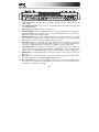
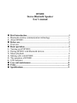
Top Panel
1
47
43 44
11 11 11 11
13 14 24 25 26
12
2 2 2 2 2 2
8
8
8
8
10
10
10
10
8
8
8
8
10
10
10
10
8
8
8
8
10
10
10
10
8
8
8
8
10
10
10
10
41
15
9
12
45
46
27 19 20 21 22 23
28 29 30 31 32
16 18
17
42
6
7
4
5 5
3
38 38 40 39 39
36 37 35 33 34
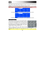
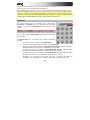
Navigation and Data Entry Controls
1.
Display: This LCD shows all the information relevant to MPC Renaissance's current operation.
Much of this information is also shown in the software. Use the Cursor Buttons to navigate through
the display, and use the Data Dial, and -/+ buttons to adjust the currently selected
setting/parameter. Use the Mode buttons to change what page is shown, and use the F-Buttons to
change what tab is shown.
Note: You can adjust the display contrast by holding down Shift and turning the Data Dial.
2.
F-Buttons: Press one of these buttons to select its corresponding tab, shown above the button in
the display.
3.
Cursor Buttons: Use these buttons to navigate through the fields of menus and options shown in
the display.
4.
Data Dial: Use this dial to scroll through the available menu options or adjust the parameter values
of the selected field in the Display.
5.
-/+: Press these buttons to increase/decrease the value of the selected field in the display.
6.
Numeric Keypad: If the selected field in the Display is a number, use these numbered buttons as a
standard numeric keypad to enter a value. Press the keypad's Enter to enter it.
7.
Undo / Redo: Press this button to undo your last action. Hold down Shift and press this button to
redo the last action you undid.
Pad and Q-Link Knob Controls
8.
Q-Link Knobs: Use these touch-sensitive knobs to adjust various parameters and settings. The
LEDs surrounding each knob indicate the knob's current position.
9.
Q-Link Trigger: Hold this button down, then touch one of the Q-Link Knobs to make that knob's
parameter's value jump to its minimum or maximum (depending on the Trig parameter in the
software).
10. Pads: Use these pads to trigger drum hits or other samples in your software. The pads are velocitysensitive and pressure-sensitive, which makes them very responsive and intuitive to play. The pads
will light up different colors, depending on how hard you play them (ranging from yellow at a low
velocity to red at the highest velocity). To disable (or re-enable) these lights, press Pad Assign then
F6 (Velo Col).
11. Pad Bank Buttons: These 4 buttons switch among Pad Banks A–H. Between these 8 banks with 16
pads per bank, you can access up to 128 MIDI events using the pads.
13
12. Pad Assign / Pad Copy: Press this button to assign a sample to a pad. In the display, the 4 x 4 grid
that appears represents the 16 pads. Use the Cursor Buttons to navigate through the grid, and use
the Data Dial or -/+ buttons to select a Program (when the Program field is highlighted) or a sample
(when a pad is highlighted).
Hold down Shift and press this button to copy the samples and parameters from one pad to another.
Use the Cursor Buttons to select the From Pad ("source") or To Pads ("destination") field and hit a
pad to select it (you can copy to multiple pads). Use the F-Buttons to confirm or cancel the
operation.
13. Full Level / Half Level: Press this button to activate/deactivate Full Level. When activated, the pads
always play back at a maximum velocity (127), no matter how hard or soft you hit them.
Hold down Shift and press this button to activate/deactivate Half Level. When activated, the pads
always play back at half-velocity (63).
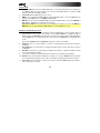
14. 16 Level: Press this button to activate/deactivate 16 Level. When activated, the last pad that was hit
will be temporarily copied to all 16 pads. The pads will now output the same note number as the
initial pad, but a selectable parameter will be fixed a specific value (ascending in value from the
lowest to highest pad), regardless of how hard you hit each pad. In the software, in the window that
appears, click the Type menu to select the parameter: Velocity, Tune, Filter, Layer, Attack, or
Decay.
You can change the pad by clicking the Pad drop-down menu in the window that appears.
Alternatively, you can press and hold the 16 Level button, press the desired pad, and then release
both.
15. Note Repeat / Latch: Hold this button down and press a pad to retrigger that pad's sample at a rate
based on the current Tempo and Time Correct settings (the available Time Correct settings will
appear in the display, which you can select with the F-Buttons). Hold down Shift and press this
button to latch the Note Repeat feature. When latched, the button does not need to be held down for
Note Repeat to be activated. Press Note Repeat once more to unlatch it.
Mode / View Controls
16. Shift: Hold this button down to access some buttons' secondary functions (indicated by orange
writing). You can also double-press it to "latch" it for a few seconds. To unlatch it, press it once more
or wait a few seconds for it to unlatch automatically.
17. Main / Track: Press this button to enter Main Mode in the display and software. Hold down Shift
and press this button to enter Track View Mode in the display and software.
14
18. Browser / Save: Press this button to view the File Browser in the display. Hold down Shift and
press this button to save the current Project (including its samples, Programs, Sequences, and
Songs).
19. Prog Edit / Q-Link: Press this button to enter Program Edit Mode in the display and software. Hold
down SHIFT and press this button to assign a parameter to a Q-Link Knob: use the Cursor
Buttons to select the desired Q-Link Knob, then use the Data Dial or -/+ buttons to select the
desired parameter.
20. Prog Mix / Track Mix: Press this button to enter Program Mixer Mode in the display and software.
Hold down Shift and press this button to enter Track Mixer Mode in the display and software.
21. Seq Edit / Effects: Press this button to enter Sequence Edit Mode. Hold down Shift and press this
button to enter the Effects page on the hardware, where you can select and route effects as well as
edit effects' parameters.
22. Sample Edit / Sample Rec: Press this button to enter Sample Edit Mode in the display and
software. Hold down Shift and press this button to enter Sample Record Mode in the display and
software.
23. Song / Other: Press this button to enter Song Mode in the display and software. Hold down Shift
and press this button to enter MIDI Control Mode, which lets you edit various MIDI parameters for
the pads, Q-Link Knobs, and certain buttons on your hardware while in this mode.
24. Step Seq: Press this button to enter Step Sequence Mode in the display and software.
25. Next Seq: Press this button to enter Next Sequence Mode in the display and software.
26. Track Mute / Pad Mute: Press this button to enter Track Mute Mode in the display and software.
Hold Shift and press this button to enter Pad Mute Mode in the display and software.
27. Window / Full Screen: When this button is lit, it means the selected field in the display contains
additional functions; press this button to access them. Use the F-Buttons, Cursor Buttons, and
Data Dial or -/+ buttons to execute (or cancel) these additional functions.
Hold Shift and press this button to switch between Full Screen and Half Screen Modes in the
software. In Full Screen Mode, the workspace occupies the whole window. In Half Screen Mode, the
parameter controls (Q-Link Knobs, pads, Sequence and Track information, Project Information, etc.)
are shown underneath the workspace.
28. Project / Folder 1: Press this button to view only Project files in the File Browser. Hold down Shift
and press this button to select the File Browser's Folder 1 shortcut.
29. Sequence / Folder 2: Press this button to view only Sequence files in the File Browser. Hold down
Shift and press this button to select the File Browser's Folder 2 shortcut.
15
30. Program / Folder 3: Press this button to view only Program files in the File Browser. Hold down
Shift and press this button to select the File Browser's Folder 3 shortcut.
31. Sample / Folder 4: Press this button to view only Sample files in the File Browser. Hold down Shift
and press this button to select the File Browser's Folder 4 shortcut.
32. No Filter / Folder 5: Press this button to view all files in the File Browser. Hold down Shift and
press this button to select the File Browser's Folder 5 shortcut.
Transport and Recording Controls
33. Play: Press this button to play the Sequence from the audio pointer's current position.
34. Play Start: Press this button to play the Sequence from its start point.
35. Stop: Press this button to stop playback.
36. Rec: Press this button to record-arm the Sequence. Press Play or Play Start to start recording.
Recording in this way (rather than using Overdub) erases the events of the current Sequence. After
the Sequence plays through once while recording, Overdub will be enabled.
37. Overdub: Press this button to enable Overdub, which allows you to record note events in a
Sequence without overwriting any previously recorded note events. You can enable Overdub either
before or during recording.
38. < / > ( |< / >| ): Use these buttons to move the audio pointer left/right, one step at a time. Hold
Locate and press one of these buttons to move the audio pointer to the previous/next event in the
Sequence Grid.
39. << / >> (Start / End): Use these buttons to move the audio pointer left/right, one bar at a time. Hold
Locate and press one of these buttons to move the audio pointer to the start or end of the Sequence
Grid.
40. Locate: Hold this button down to activate the secondary functions of the < / > and << / >> buttons
(i.e., |< / >| and Start / End, respectively).
41. Erase: As a Sequence is playing, hold this button down and press a pad to delete the note event for
that pad at the current playback position. This is a quick way to delete note events from your
Sequence without having to stop playback.
42. Tap Tempo: Press this button in time with the desired tempo to enter a new tempo (in BPM) in the
software.
16
I/O and Level Controls
43. Mic In / Phono In Switch: Use this switch to select the Mic In or Phono In jacks on the rear panel.
If you are using a mic or other line-level audio source connected to the Mic In jacks, select Mic In. If
you are using a phono-level device like a turntable connected to the Phono In jacks, select Phono
In.
44. Rec Gain: Use this knob to adjust the gain of the incoming signal from the Mic In or Phono In jacks
on the rear panel. Monitor the recording level by viewing the level meter (LEDs) above the Mic In /
Phono In Switch. Be careful when setting this knob at higher levels, which can cause the signal to
distort.
45. Direct Mon: Use this knob to adjust the balance between the Input and Comp signals in the
headphones. The Input signal consists of the Mic In or Phono In jacks—turn the knob all the way to
Input for zero-latency direct monitoring. The Comp signal is the normal software playback. When
not recording, we recommend turning this knob all the way to the Comp position.
46. Main Volume: Use this knob to adjust the volume level of the Stereo Out jacks.
47. Vintage Mode: Press this to toggle through the available Vintage Modes. The MPC3000 and
MPC60 settings emulate the sounds of those classic MPCs, while the Other setting emulates the
sound of vintage sampling drum machines. When none of the LEDs are lit, Vintage Mode is off.
Front Panel
1.
Footswitch Inputs: Connect optional
1/4" TS footswitches to these inputs.
2.
Mix Knob: Use this knob to adjust the
balance between the Main and Assign
signals in your headphones. The Main
signal is the Stereo Outs. The Assign signal is the Assignable Mix Outs 1 and 2.
3.
Headphones: Connect your headphones (not included) to one of these standard TRS outputs (1/8"
or 1/4"). Use the Mix Knob to determine what signal is heard in the headphones.
4.
Headphones Volume: Use this knob to adjust the headphone volume.
1 1
17
2
3 3
4
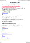
Rear Panel
9
9
14
12
10 11 13
6
7
2
8
16 16 16 16 15 15
5 4
1 3
1.
Power Input: Connect a 12V DC, 2A power adapter (center pin positive) to this jack then into an
electrical outlet.
2.
Power Adapter Restraint: You can secure a power adapter cable to this restraint to prevent it from
accidentally unplugging.
3.
Power Switch: Turns MPC Renaissance's power on/off.
4.
Computer USB Port: Use the included USB cable to connect this high-retention-force USB port to
an available USB port on your computer. This connection allows MPC Renaissance to send/receive
MIDI and audio data to/from the MPC software.
5.
USB Hub Outputs: You can connect additional USB devices (controllers, hard drives, etc.) to these
powered, high-speed USB 2.0 ports. In addition to being an audio interface, these ports allow MPC
Renaissance to function as a powered USB hub when it is powered on.
6.
Stereo Out: Connect these 1/4" TRS outputs to your speaker system (not included). The signal sent
out of these outputs is the main mix. In the MPC software, you can set what is routed to these
outputs in the Program Mixer tab, by selecting 1,2 as the Out for one pad or multiple pads.
7.
Assignable Mix Out: Connect these 1/4" TRS outputs to an external mixer (not included). The
signal sent from these outputs is full-volume (0 dB). In the MPC software, you can set what is routed
to these outputs in the Program Mixer tab, by selecting 3,4 as the Out for one pad or multiple pads.
8.
S/PDIF In/Out: Use standard RCA cables to connect these jacks to devices that can send/receive
digital audio.
9.
Mic In: Connect an external sound source or microphone to these jacks using standard 1/4" TRS or
XLR cables. Make sure to set the Mic / Line Switch appropriately.
10. Mic / Line Switch: Set this switch appropriately for the device you connected to the Mic In jacks. If
your sound source is a microphone, set it to Mic. If your sound source is a line-level device, like an
external mixer or keyboard, set it to Line.
18
11. Phantom Power Switch: This switch activates and deactivates phantom power. When activated,
phantom power supplies +48V to both Mic In inputs. Please note that most dynamic microphones do
not require phantom power, while most condenser microphones do. Consult your microphone's
documentation to find out whether it needs phantom power.
12. Phono In: Connect these RCA inputs to an external sound source (e.g., a turntable, CD player,
etc.). Make sure to set the Phono / Line Switch appropriately.
13. Phono / Line Switch: Flip this switch to the appropriate position, depending on the device
connected to the Phono In jacks. If you are using phono-level turntables, set this switch to Phono to
provide the additional amplification needed for phono-level signals. If using a line-level device, such
as a CD player or sampler, set this switch to Line.
14. Ground Terminal: If you connected a phono-level turntable to the Phono In jacks and are hearing a
low hum or buzz, this could mean that the turntable is not grounded. If the turntable has a grounding
wire, connect it to this terminal.
Note: Some turntables have a grounding wire built into the RCA connection and, therefore, nothing
needs to be connected to the grounding terminal.
15. MIDI In: Use a five-pin MIDI cable to connect the MIDI Out of an optional external MIDI device to the
MIDI In of MPC Renaissance.
16. MIDI Out: Use a five-pin MIDI cable to connect the MIDI Out of MPC Renaissance to the MIDI In of
an optional external device.
19
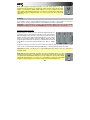
MPC Studio
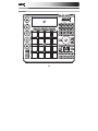
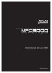
Top Panel
3
13
4 1
2
5
16 16 16 16 17
12
6
6
6
6
6
12
18 19 29 30 31
24 25 26 27 28
33 34 35 36 37
12
12
6
22
15
21 5
47
14
10
8
23
5
7
32
11
46
43 43 45 44 44
20
41 42 40 38 39
20
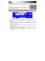
Power and I/O
1.
Computer USB Port: Use the included USB cable to connect this high-retention-force USB port to
an available USB port on your computer. This connection allows MPC Studio to send/receive MIDI
and audio data to/from the MPC software.
2.
Power Switch: Turns MPC Studio's power on/off.
3.
MIDI In: Use the included 1/8"-MIDI adapter and a five-pin MIDI cable to connect the MIDI Out of an
optional external MIDI device to the MIDI In of MPC Studio.
4.
MIDI Out: Use the included 1/8"-MIDI adapter and a five-pin MIDI cable to connect the MIDI Out of
MPC Studio to the MIDI In of an optional external device.
Important: Do NOT connect audio devices (e.g., headphones, monitors, etc.) to the 1/8" MIDI In or
MIDI Out jacks. Use the included 1/8"-MIDI adapters to connect MIDI devices only.
Navigation and Data Entry Controls
5.
Display: This LCD shows all the information relevant to MPC Studio's current operation. Much of
this information is also shown in the software. Use the Cursor Buttons to navigate through the
display, and use the Data Dial, and -/+ buttons to adjust the currently selected setting/parameter.
Use the Mode buttons to change what page is shown, and use the F-Buttons to change what tab is
shown.
Press and hold Shift and turn the Data Dial to adjust the contrast of the display.
6.
F-Buttons: Press one of these buttons to select its corresponding tab, shown above the button in
the display.
7.
Cursor Buttons: Use these buttons to navigate through the fields of menus and options shown in
the DISPLAY.
8.
Data Dial: Use this dial to scroll through the available menu options or adjust the parameter values
of the selected field in the display.
9.
-/+: Press these buttons to increase/decrease the value of the selected field in the display.
10. Numeric: If the selected field in the display is a number, you can press Numeric and use the pads
as a standard numeric keypad to enter a value. The numbers are printed in green above the pads.
11. Undo / Redo: Press this button to undo your last action. Hold down Shift and press this button to
redo the last action you undid.
21
Pad and Q-Link Knob Controls
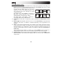
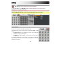
12. Q-Link Knobs: Use these touch-sensitive knobs to adjust various parameters and settings. The
knobs can control one column of parameters at a time. Use the Scroll Knob above them to change
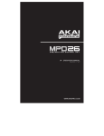
which column or row of parameters they currently control.
In modes where the display shows a "4 x 4" array of
parameters, you will see an additional indicator on the
top or left side of the array, indicating the currently
controlled row/column.
The Q-Link Knobs control columns of parameters in
Main Mode, Program Edit Mode, Track View Mode,
Sample Edit Mode, and Step Sequence Mode.
The Q-Link Knobs control rows of parameters in
Program Mixer Mode and Track Mixer Mode.
Row 1
Row 2
Row 3
Column 1
Column 2
Column 3
Row 4
Column 4
13. Scroll Knob: Use this knob to change which column of parameters the Q-Link Knobs currently
control.
14. Q-Link Trigger: Hold this button down, then touch one of the Q-Link Knobs to make that knob's
parameter's value jump to its minimum or maximum (depending on the Trig parameter in the
software).
15. Pads: Use these pads to trigger drum hits or other samples in your software. The pads are velocitysensitive and pressure-sensitive, which makes them very responsive and intuitive to play. The pads
will light up different colors, depending on how hard you play them (ranging from yellow at a low
velocity to red at the highest velocity). To disable (or re-enable) these lights, press Pad Assign then
F6 (Velo Col).
If the selected field in the display is a number, you can press Numeric and use the pads as a
standard numeric keypad to enter a value. The numbers are printed in green above the pads.
16. Pad Bank Buttons: These 4 buttons switch among Pad Banks A–H (press and hold Shift to access
Banks E–H). Between these 8 banks with 16 pads per bank, you can access up to 128 MIDI events
using the pads.
22
17. Pad Assign / Pad Copy: Press this button to assign a sample to a pad. In the display, the 4 x 4 grid
that appears represents the 16 pads. Use the Cursor Buttons to navigate through the grid, and use
the Data Dial or -/+ buttons to select a Program (when the Program field is highlighted) or a sample
(when a pad is highlighted).
Hold down Shift and press this button to copy the samples and parameters from one pad to another.
Use the Cursor Buttons to select the From Pad ("source") or To Pads ("destination") field and hit a
pad to select it (you can copy to multiple pads). Use the F-Buttons to confirm or cancel the
operation.
18. Full Level / Half Level: Press this button to activate/deactivate Full Level. When activated, the pads
always play back at a maximum velocity (127), no matter how hard or soft you hit them.
Hold down Shift and press this button to activate/deactivate Half Level. When activated, the pads
always play back at half-velocity (63).
19. 16 Level: Press this button to activate/deactivate 16 Level. When activated, the last pad that was hit
will be temporarily copied to all 16 pads. The pads will now output the same note number as the
initial pad, but a selectable parameter will be fixed at the values shown in the diagram on the right,
regardless of how hard you hit them. In the software, in the window that appears, click the Type
menu to select the parameter: Velocity, Tune, Filter, Layer, Attack, or Decay.
You can change the pad by clicking the Pad drop-down menu in the window that appears.
Alternatively, you can press and hold the 16 Level button, press the desired pad, and then release
both.
20. Note Repeat / Latch: Hold this button down and press a pad to retrigger that pad's sample at a rate
based on the current Tempo and Time Correct settings (the available Time Correct settings will
appear in the display, which you can select with the F-Buttons). Hold down Shift and press this
button to latch the Note Repeat feature. When latched, the button does not need to be held down for
Note Repeat to be activated. Press Note Repeat once more to unlatch it.
Mode and View Controls
21. Shift: Hold this button down to access some buttons' secondary functions (indicated by orange
writing). You can also double-press it to "latch" it for a few seconds. To unlatch it, press it once more
or wait a few seconds for it to unlatch automatically.
22. Main / Track: Press this button to enter Main Mode in the display and software. Hold down Shift
and press this button to enter Track View Mode in the display and software.
23
23. Browser / Save: Press this button to view the File Browser in the display. Hold down Shift and
press this button to save the current Project (including its samples, Programs, Sequences, and
Songs).
24. Prog Edit / Q-Link: Press this button to enter Program Edit Mode in the display and software. Hold
down Shift and press this button to assign a parameter to a Q-Link Knob, use the Cursor Buttons
to select the desired Q-Link Knob, then use the Data Dial or -/+ buttons to select the desired
parameter.
25. Prog Mix / Track Mix: Press this button to enter Program Mixer Mode in the display and software.
Hold down Shift and press this button to enter Track Mixer Mode in the display and software.
26. Seq Edit / Effects: Press this button to enter Sequence Edit Mode. Hold down Shift and press this
button to enter the Effects page in the display, where you can select and route effects as well as edit
effects' parameters.
27. Sample Edit / Sample Rec: Press this button to enter Sample Edit Mode in the display and
software. Hold down Shift and press this button to enter Sample Record Mode in the display and
software.
28. Song / Other: Press this button to enter Song Mode in the display and software. Hold down Shift
and press this button to enter MIDI Control Mode, which lets you edit various MIDI parameters for
the pads, Q-Link Knobs, and certain buttons on your hardware while in this mode.
29. Step Seq: Press this button to enter Step Sequence Mode in the display and software.
30. Next Seq: Press this button to enter Next Sequence Mode in the display and software.
31. Track Mute / Pad Mute: Press this button to enter Track Mute Mode in the display and software.
Hold Shift and press this button to enter Pad Mute Mode in the display and software.
32. Window / Full Screen: When this button is lit, it means the selected field in the display contains
additional functions; press this button to access them. Use the F-Buttons, Cursor Buttons, and
Data Dial or -/+ buttons to execute (or cancel) these additional functions.
Hold Shift and press this button to switch between Full Screen and Half Screen Modes in the
software. In Full Screen Mode, the workspace occupies the whole window. In Half Screen Mode, the
parameter controls (Q-Link Knobs, pads, Sequence and Track information, Project Information, etc.)
are shown underneath the workspace.
33. Project / Folder 1: Press this button to view only Project files in the File Browser. Hold down Shift
and press this button to select the File Browser's Folder 1 shortcut.
34. Sequence / Folder 2: Press this button to view only Sequence files in the File Browser. Hold down
Shift and press this button to select the File Browser's Folder 2 shortcut.
24
35. Program / Folder 3: Press this button to view only Program files in the File Browser. Hold down
Shift and press this button to select the File Browser's Folder 3 shortcut.
36. Sample / Folder 4: Press this button to view only Sample files in the File Browser. Hold down Shift
and press this button to select the File Browser's Folder 4 shortcut.
37. No Filter / Folder 5: Press this button to view all files in the File Browser. Hold down Shift and
press this button to select the File Browser's Folder 5 shortcut.
Transport and Recording Controls
38. Play: Press this button to play the Sequence from the audio pointer's current position.
39. Play Start: Press this button to play the Sequence from its start point.
40. Stop: Press this button to stop playback.
41. Rec: Press this button to record-arm the Sequence. Press Play or Play Start to start recording.
Recording in this way (rather than using Overdub) erases the events of the current Sequence. After
the Sequence plays through once while recording, Overdub will be enabled.
42. Overdub: Press this button to enable Overdub, which allows you to record note events in a
Sequence without overwriting any previously recorded note events. You can enable Overdub either
before or during recording.
43. < / > ( |< / >| ): Use these buttons to move the audio pointer left/right, one step at a time. Hold
Locate and press one of these buttons to move the audio pointer to the previous/next event in the
Sequence Grid.
44. << / >> (Start / End): Use these buttons to move the audio pointer left/right, one bar at a time. Hold
Locate and press one of these buttons to move the audio pointer to the start or end of the Sequence
Grid.
45. Go To: Hold this button down to activate the secondary functions of the < / > and << / >> buttons
(i.e., |< / >| and Start / End, respectively).
46. Erase: As a Sequence is playing, hold this button down and press a pad to delete the note event for
that pad at the current playback position. This is a quick way to delete note events from your
Sequence without having to stop playback.
47. Tap Tempo: Press this button in time with the desired tempo to enter a new tempo (in BPM) in the
software.
25
Quick Start / Tutorial
This chapter should help you to familiarize yourself with some basic MPC features. To get the most out of
this tutorial, we recommend reproducing each of the described steps.
The MPC hardware's display reflects what it is controlling in the software, but due to space and character
limitations, the hardware display is slightly different (e.g., parameter names may be abbreviated, the
layout may be different or spread across multiple tabs, etc.).
Hardware:
•
You can navigate through the MPC hardware display by using the MPC hardware's Cursor
Buttons. When a parameter is selected, you can change it by turning the hardware's Data Dial or
using the -/+ buttons.
•
When the MPC hardware display shows a series of parameters that cannot be selected with the
Cursor Buttons, that means it is showing you what the Q-Link Knobs are controlling. When you
touch a Q-Link Knob, the parameter's name and setting will appear in the upper-right corner of the
hardware display. Turn the knob to adjust it (If the Q-Link Knob does not control any parameter in
the display, this area will show the Q-Link Knob number and no text).
MPC Studio users: MPC Studio's Q-Link Knobs control one column of parameters at a time. Whenever
this manual instructs you to use the Q-Link Knobs to adjust parameters, you can use the Scroll Knob
(above the Q-Link Knobs) to move through the different columns.
On the following pages we will create a short song to show you important aspects of using the MPC
software in conjunction with the MPC hardware. Let's get started!
Starting Up
1.
Power on your computer, and make sure the MPC hardware driver and software are both properly
installed on your computer.
2.
Connect your MPC hardware to your computer with a standard USB cable and power it on. After
that, open the MPC software.
Now, you're ready to go!
26
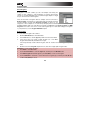
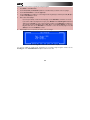
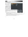
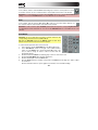
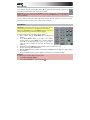
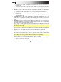
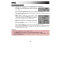
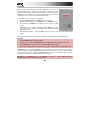
Creating a Drum Kit
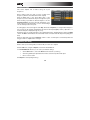
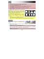
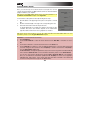
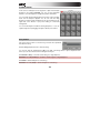
Let's start by making a simple drum kit.
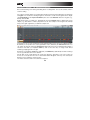
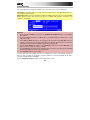
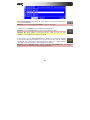
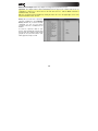
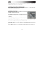
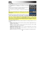
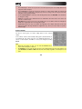
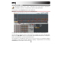
The Browser display of the MPC hardware
Hardware:
1.
Press the Browser button and use Cursor Buttons to navigate to where your drum sounds are
located:
•
Use the Up or Down Cursor Buttons to move through a list
•
Use the Right Cursor Button to enter a selected folder,
•
Use the Left Cursor Button to go to the previous folder.
2.
To preview a selected sound, press the F3 button (Play). You can also activate the Auto Preview
option with the F2 button (Auto).
3.
First, let's load a bass drum. Hit Pad 1 to select it. The pad will be lit in green. Navigate to a bass
drum sample you like and press F6 (Open) to assign it to the selected pad. Now, you can press Pad
1 to play the bass drum sample.
4.
To create a simple drum set, repeat the above steps for other pads. We recommend loading a snare
drum, a closed hi-hat, and an open hi-hat. Feel free to add a crash cymbal, too.
Now that your drum kit is set up, you can record a drum Sequence!
27
Recording a Drum Sequence
Let's record a drum Sequence.
Hardware:
1.
Press the Rec button to activate Record Mode.
2.
To start the actual recording, press the Play button. The pre-count will count one measure before
the software starts to record. We recommend recording only one sound (pad) at a time, especially if
you are not familiar with playing on the pads.
3.
Play a simple bass drum pattern. The note events you just recorded will automatically be placed in
the grid (in this case, on 16th notes). The initial measure length is two bars. After the two bars, the
recording will enter Overdub Mode automatically; the Sequence plays again from the beginning and
keeps looping, allowing you to record further notes. Don't stop the recording!
4.
Play the snare drum part, then a hi-hat part.
5.
When you're done recording, press the Stop button.
6.
To repeat the recording, keep in mind that the pads you play in your new recording will automatically
replace existing notes played with the same pads. To prevent this, you can start again from Step 1
but press the Overdub button instead of the Rec button; Overdub lets you record additional note
events over the existing Sequence.
7.
The Undo button functions differently while in Record Mode. Normally, pressing Undo will undo just
the last event. When there is an event to undo, the Undo button will be lit solid. While recording, the
Undo button will flash. In this case, pressing Undo will erase all events from that recording (i.e.,
since Play or Play Start was pressed).
8.
Want to add a crash cymbal? In this case, it is easier to create it directly in the software by clicking
the desired position in the grid, in the same row as the crash sample.
Now that you've recorded a Sequence using multiple pads, let's look at how you can edit and organize it.
28
Organizing Samples and Editing Note Events
We recommend doing some naming and editing before recording further. Let's use the software, which is
easier for editing.
The collection of drum samples you loaded earlier (and their respective pad assignments) are arranged in
a Program. Let's rename the exisiting Program as we'll want to create more Programs later on. Rightclick Program 001 in the Project Information panel, and select Rename. Name the Program (e.g.,
Drums), and click OK.
Right-click the name of a sample (e.g., Bassdrum-01), and select Rename. Enter a suitable name for the
sample (e.g., Bass Drum 1 or Kick 1). Repeat this for the other samples in the Program. This will help
keep your Program organized as you add more samples to it.
In the grid, you can see your recorded note events. Click and drag a note to move it to a different position.
By default, you can position notes only by quantization values, defined by the Time Correct value. You
can change the value by clicking the Time Correct drop-down menu. We recommend working with 8 or
16 values. Hold down your keyboard's Shift key and use the arrow keys to nudge events without
restricting ("snapping") them to the grid.
Hold down your keyboard's Control key (Windows) or Command key (Mac OS X) and click and drag a
note to copy it. Double-click a note to delete it.
Velocity data can be easily edited in the velocity lane below the grid. Click a note event or place the
mouse over a velocity bar in the lane. A small round handle will appear at the top of the velocity bar.
Move the mouse vertically to change its value.
Let's make some basic edits to the sound of the Sequence.
29
Making Basic Sound Edits
Let's make sure the samples are properly tuned and have good levels.
Hardware:
1.
Press the Prog Mix button to enter Program Mixer Mode.
2.
Press the F1 button (Level) to control the volume for each pad. You can use the hardware's Q-Link
Knobs as well as the corresponding faders in the software. Adjust the levels of each pad to suit your
taste.
3.
Press F2 (Pan) to control the stereo panning for each pad. You can use the hardware's Q-Link
Knobs as well as the corresponding Pan knob in the software. We recommend spreading the
panning of the bright sounds (e.g., cymbals, snare drum) a little.
4.
The snare drum needs a small amount of reverb to give it a more spatial sound. Press F5 (Insert) to
view the Insert Effect tab. Use the Cursor Buttons to navigate to the snare sample's pad (here,
A02). Using the Data Dial, select the desired effect, and press F4 (Select) to load it. Let's try Reverb
Medium.
5.
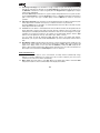
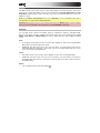
Could the bass drum use some tuning? Press the Prog
Edit button and hit Pad 1 to select the bass drum. Press
F2 (Samples) and use the Q14 and Q15 Q-Link Knobs
to tune the sound. You can also use the corresponding
Semi and Fine parameter in the Layer section of the
software.
Next, we'll add a new sound.
30
Recording a Bass Track
Let's try recording a bass line. Unlike a drum kit, it's important to be able to play and record a bass sound
chromatically, so this will be slightly different than setting up the drum kit.
Adding a bass line over the drum part means we need to add a new Track. A Track is simply a layer of a
Sequence; you can have multiple Tracks in a single Sequence (e.g., a drum Track, a bass Track, a piano
Track, etc.), and they all play simultaneously when you play the Sequence.
First, select a new Track. Go back to Main Mode and select Track 2 (unused) in the Track drop-down
menu above the grid.
Hardware: Press the Main button and then press the F4 button (Track+) to move to the next Track.
Let's create a new Program to assign to this empty Track:
1.
In the Track Section in the lower half of the window, click the + button next to the Program dropdown menu.
2.
In the Project Information Section on the right, right-click the new Program (Program 001) and
enter a name (e.g., Bass).
3.
Back in the Track Section, click the Type drop-down menu and select Keygroup. This is necessary
because we want to play the bass sound chromatically with the pads.
Now, let's load a bass sound:
1.
Click the File Browser's drop-down menu for
an overview of your hard disk structure and
select a location. Double-click any displayed
folder in the File Browser to open it.
2.
Locate and select a bass sample. Click the Preview button to preview any selected audio
sample.
3.
Double-click a sample to add it to the Project. (Keep in mind that the sample is not yet assigned to a
pad.)
31
Let's continue to set up the Keygroup Program:
1.
Click the Program Edit tab to enter Program Edit Mode.
Hardware: Press the Prog Edit button to enter Program Edit Mode.
2.
In the Layer section, click the Layer 1 drop-down menu and
select the bass sample you just loaded (you'll see your drum
samples in this list, as well). Because you're working with a
Keygroup Program instead of a Drum Program, this sample is
now playable across all pads.
Tip: On your MPC hardware, press the Pad Bank D button to switch to Pad Bank D and hit Pad 13.
You should hear the bass sample played back with its original pitch. You can use the other pads to
play your sample chromatically.
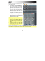
Let's add a second layer and set the Layers' velocity ranges so our bass sounds different when played at
a higher velocity (as a real bass would):
1.
Go back to the File Browser and select a different bass sample that sounds similar but a little bit
brighter.
2.
Double-click a sample to add it to the Project.
3.
Back in the Layer section, click the Layer 2 drop-down menu and select the new bass sample. Hit a
pad—both samples will sound at once. Maybe this new sound is interesting as it is, but let's make
some quick edits to get as close as we can to a real-life bass sound.
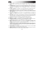
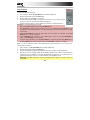
4.
Set Layer 1's Velocity slider to
cover the velocity range from 0 to
80, and set Layer 2's Velocity slider
to cover the range from 81 to 127.
Now when you hit a pad, the lower
velocities will trigger the Layer 1 sample
only, while higher velocities will trigger the
Layer 2 sample only.
32
Let's record that bass line now. Prepare your recording as described earlier, and record some bass notes.
You can edit your recording just like we've done earlier.
Once you've recorded it, let's tweak it a bit in the Filter section of the Program Edit menu. For this, let's
use the MPC hardware.
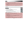
Hardware:
1.
Press Prog Edit to enter Program Edit Mode, and press F4 (Flt Env) to
enter the Filter page.
2.
Turn Q-Link Knob 13 to select a filter for the Filter Type field. We
recommend working with the Low 4 type, to start.
3.
Turn the Cutoff and Reso (Resonance) knobs (Q-Link Knobs Q14 and
Q15) until your bass sample sounds perfect to you.
4.
Use the Q-Link Knobs Q1 to Q4 to set the Amp Atk (Amplifier
Envelope Attack) and Amp Rel (Amp Envelope Release). These control
the overall level characteristics of the sound.
5.
Do you want to add an effect (e.g., Chorus)? Press F6 (Effects) and
select the desired effect type for your bassline. (Remember to turn the
Inserts parameter in the upper-right corner of the display to On.)
So far, we've created a simple drum Sequence and a bass line to go with it. Repeat this process to create
a second Sequence. Even with just these two Sequences, you have the foundation of a Song, which we'll
explain next.
33
Creating a Song
This section explains how to make a Song out of your
Sequences.
Before starting, make sure that you have recorded some
Sequences (which we described earlier in this chapter)!
Click the Song tab to open Song Mode. Each of the
Sequences you've created in this Project is assigned to a pad.
Click and drag a pad with the desired Sequence onto the
Sequence Playlist to the left of the pads. Alternatively, if you
prefer viewing a horizontal timeline, you can click and drag it
onto the workspace above the pads.
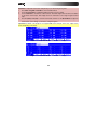
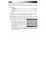
As a Song plays, it moves through the each Step, which has a Sequence you assigned. Each Sequence
may (or may not) be repeated, determined by the value in the Repeats (Rpts) column (a Rpt value of 1
means the Sequence will play through only once).
Each Step can be set to play its Sequence at an independent tempo, determined by the value in the BPM
column. The Bars column indicates the total number of bars or measure that will elapse when playing that
Step.
Click any drop-down menu in the Sequence column to select a new Sequence for that Step. Click and
drag up or down on a Rpts value to change it.
Exporting the Song
Want to share your new Song with your friends? All you need to do is export it.
Click the File menu, navigate to Export, and select As Audio Mixdown.
In the Audio Mixdown window, you can select your mixdown settings.
•
Set the Start field to 1, and set the End field to the last bar of your Song.
•
As the Song will likely be uploaded to the Internet, select the mp3 file format option.
•
Choose a save location.
Click Export to start exporting the Song.
34
Other Features Explained
This chapter describes various advanced features. These sections explain how to perform these
operations by using mostly the MPC hardware, but all of them are also possible in the software. For a
fuller explanation of these features, please refer to their corresponding sections in the Operation
(Software) chapter.
Step Sequencer
You've already learned how to record note events on a Track, but you can quickly enter note events in
Step Sequence Mode by using the pads as "step buttons," simulating the experience of a traditional stepsequencer-style drum machine.
Hardware:
1.
Press Step Seq to enter Step Sequence Mode.
2.
Start a new Track by using the Cursor Buttons to select the Trk field and use the Data Dial or -/+
buttons to select an unused Track. Let's use Track 04.
3.
Use the F2 (Bar-) and the F3 (Bar+) buttons to select the bar whose steps you want to create or
edit.
4.
Use F5 (Pad-) and F6 (Pad+) to select the pad whose steps want to create or edit. The pad number
and its sample name will appear in the upper-right corner of the display. Alternatively, you can use
the Cursor Buttons to select the Pad field in the upper-right corner and use the Data Dial or -/+
buttons to select a pad.
5.
Press the Play button to start your Sequence.
•
Each pad represents a step in the bar. If the pad already has note events on the selected Track, the
corresponding pads (steps) will be lit with colors corresponding to their velocities.
•
Hit an unlit pad to enter a note event at that step. The pad will light up with a color corresponding to
its velocity.
•
Click a lit pad to delete the note event from that step. The pad will be unlit.
See the Step Sequence Mode chapter to learn more about this feature.
35
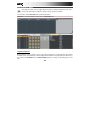
Drum Loops and Chop Mode
Modern music producers often use drum loops to add grit and nuance to programmed beats. This section
explains how to use Sample Edit Mode to work with drum loops.
Use the File Browser to locate a drum loop on your hard disk (the loop does not have to match the tempo
of anything in the Project). Double-click the desired drum loop to add it to the current Program.
Hardware:
1.
Press the Sample Edit button to enter Sample Edit Mode.
2.
Use the Data Dial to select the loaded drum loop. You can scroll through all loaded samples seen
the top of your MPC hardware display.
3.
Press F1 (Chop) to enter the Chop Mode where the drum loop will be cut into slices.
4.
Use the Cursor Buttons to select the Threshold parameter, and use the Data Dial or -/+ buttons
select a value. The higher the value, the more slices will be created. Be sure to select a value so that
every transient peak of the drum loop has a corresponding a slice marker.
Tip: Press F4 (Audition) to play the created slices with the pads. Each slice will be automatically
assigned to a pad: Pad A01 plays Slice 1, Pad A02 plays Slice 2, etc.
36
Hardware:
Now, let's create a new Program containing all of these slices as individual samples. It will also
automatically create corresponding note events to play back these slices sequentially.
1.
Press F5 (Convert) to enter the Convert Slices page.
2.
Use the Cursor Buttons to navigate to the following parameters and use the Data Dial or -/+
buttons select the value indicated as follows: Convert to Sliced Samples, Crop Samples to On,
Create New Program to On, Create Events to On, and Number Of Bars to the bar length of your
recorded Track (if you're working with the same one from the earlier tutorial, set it to 2).
3.
Press F6 (Do It) to proceed. Each slice will be assigned to a pad, and each pad will have a recorded
note event in the Track. When you play that Track, it will play each pad (each slice) in the original
order.
4.
Press Play and listen to how the drum loop matches your Song tempo now.
You can also edit the note events of the drum loop slices—enter Main Mode to do this. A new Track with
the note events playing their corresponding slices has been automatically created. Click the T Correct
drop-down menu to use Time Correct to quantize the note events so they fall on exact, even time
intervals. You can also rearrange the note events, thus creating a new playback order for the slices. You
can also edit each slice or sample in Program Edit Mode. You can add effects for slices or use the filter
function to change the frequency range of a selected slice. There are almost no limits to what you can do.
See the Chop Mode part of the Sample Edit Mode chapter to learn more about this feature.
37
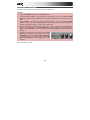
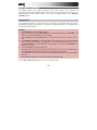
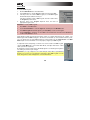
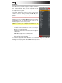
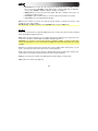
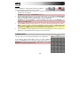
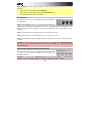
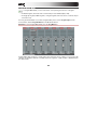
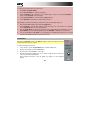
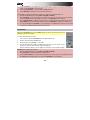
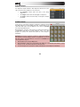
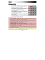
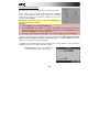
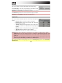
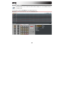
Pad Muting and Track Muting
Pad Mute Mode and Track Mute Mode let you silence different pads and Tracks to see what the
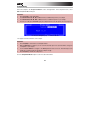
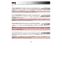
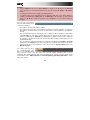
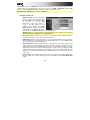
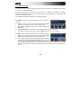
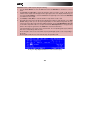
Sequence sounds like without those samples or parts.
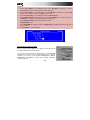
The Pad Mute display of the MPC hardware
Hardware:
1.
Select your basic drum Track.
2.
Press and hold the Shift button and press the Track Mute / Pad Mute button to enter Pad Mute
Mode.
3.
Press Play to play the Sequence.
4.
Mute a pad by pressing it once. The muted pad will be lit red. You can mute multiple pads at the
same time.
5.
To mute pads on another Track, press Shift + Main / Track and press F3 (Track-) or F4 (Track+) to
switch between the recorded Tracks. Press Shift + Track Mute / Pad Mute again to perform the
desired mutes.
38
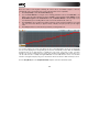
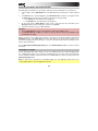
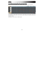
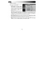
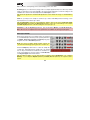
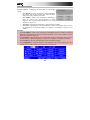
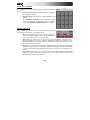
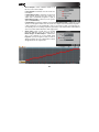
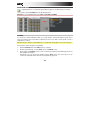
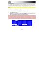
You can also mute entire Tracks by using the similar Track Mute function.
The Track Mute display of the MPC hardware
Hardware:
1.
Press the Track Mute button to enter Track Mute Mode.
2.
Press Play to play the Sequence.
3.
Mute a Track by hitting the corresponding pad once. The muted pad will be lit red. You can mute
multiple pads at the same time.
4.
To mute a Track only at precise note intervals ("quantizing" your mutes, essentially), you can set a
musical timing value by pressing the F4 button (Time Div). Use the Data Dial or -/+ buttons to set a
musical value (e.g., 1 bar). Press F4 (Close) to close the page. Now, when you hit a pad in Track
Mute Mode, the mute will occur precisely at the beginning of the following bar. This lets you test
musical combinations of patterns—the stage preliminary to building a Song structure.
39
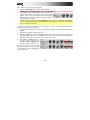
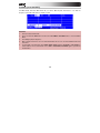
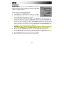
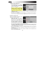
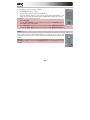
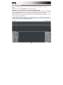
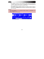
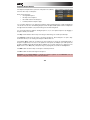
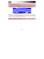
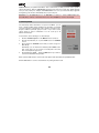
Sample Recording
This section describes recording new samples of your own, which you can use in your Projects.
Important: To record any audio, you need to connect an audio source to your MPC Renaissance or to
your computer's audio interface.
MPC Studio users: This section describes recording using MPC Renaissance as your sound card. MPC
Studio cannot be used in this way, but you can use a separate audio interface connected to your
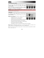
computer to record audio.
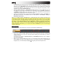
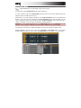
The Sample Record display of the MPC hardware
Hardware:
1. Press and hold the Shift button and press the Sample Edit / Sample Rec button to enter Sample
Record Mode.
2. Connect a suitable microphone to a Mic In jack of your MPC Renaissance. Make sure to set the
input switch to Mic.
3. Set the Mic In / Phono In switch on the top panel to Mic In and turn up the Rec Gain dial. In the
software you should now see the input signal. Make sure that the signal gain does not exceed the
maximum level (the top input level display segment should be hardly lit).
4. Use the Cursor Buttons to navigate to the Threshold parameter and use the Data Dial or -/+
buttons to set it to a fairly low level (e.g., -70 dB).
5. Press F6 (Record) and sing/say/shout something into the microphone. Recording starts immediately
when the input signal level reaches the threshold value.
6. Press F6 (Stop) again, to stop recording.
If you're happy with your recording, name the new sample in the software in the window that appears
when you stop recording. You should also assign the sample to an unused pad. Simply hit the pad to
assign the sample! After that, click Keep.
See the Sample Record Mode chapter to learn more about this feature.
40
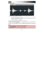
Sample Editing
Select the sample in the Project Information section and right-click it. In the drop-down menu, select
Edit. Sample Edit Mode will open.
Hardware:
1.
Press F2 (Trim) to enter Trim Mode.
2.
Use Q-Link Knobs Q1, Q5, Q9, or Q13 to define a suitable start point for your sample.
3.
Use Q-Link Knobs Q2, Q6, Q10, or Q14, to define a suitable end point for your sample.
4.
To hear your edits, press Pad A15 to play the sample from the new start point to the new end point.
The Process Sample display of the MPC hardware
Let's apply some transformations to the sample.
Hardware:
1.
Press F6 (Edit) to enter the Process Sample window.
2.
With the Data Dial or -/+ buttons you can select the desired option. Let's try Pitch Shift to change the
overall pitch of your sample.
3.
Use the Cursor Buttons to navigate to the Pitch parameter and set it to 5.0. This will transpose the
sample by 5 semitones without affecting the sample's length.
4.
Press F5 (Do It) to finalize the edit process.
See the Sample Edit Mode chapter to learn more about this feature.
41
Automating Parameters with the Q-Link Knobs
Automating various parameters is a good way to add some motion and dynamism to your Sequences.
1. In the software, click the Main Mode tab to open Main Mode. Hit a pad that has a sample assigned
to it.
2. In the Q-Link section, click the Prg button. Turn Q-Link Knob Q1 to activate it for assignment. Click
the Pad field and select the pad you hit earlier, and select the following settings:
• In the Param field, select Filter Cutoff as parameter.
• In the Change field, select Real Time as the parameter.
3. Do the same steps for Q-Link Knob 2: assign it to the same pad, and select Real Time as the
Change parameter, but select Filter Reso (resonance) for Param.
4. Record the automation using your MPC hardware:
Hardware:
1. Press the Overdub button to arm your automation recording. Press Play to start it.
2. Use Q-Link Knobs Q1 and Q2 to record filter movement as desired. After that, press Stop to finish
the automation recording.
Want to see what you've recorded? In the software, to the left of the velocity lane under the grid, click the
Automation menu, select Real Time, and select RT Filter cutoff and RT Filter resonance. The
parameters will appear below it. Click either one to show its automation data. Click an automation anchor
point to edit the automation.
See the Recording and Editing Automation part of the General Features chapter to learn more about
this feature.
Using MPC as a Plugin
If you're working with other audio software, you can use the MPC software as an instrument plugin (VST,
AU, or RTAS format) within your host software. The MPC plugin offers the same features and functionality
as the standalone software version but with some notable differences, which are discussed in the
Operation (Plugin) chapter.
Note: To learn how to load and use an instrument plugin in a host application, please refer to the
corresponding chapter of your host application's manual.
42
Operation (Software)
This chapter explains the complete features and functions of the MPC software.
Important: When using the MPC software as a plugin, its features and functions are very similar to how it
is described in this chapter but with some notable differences, discussed in the Operation (Plugin)
chapter.
Remember:
•
In this manual, whenever the MPC hardware can be used to control a parameter or a function, this is
explained separately in a light-red box labeled Hardware, MPC Renaissance, or MPC Studio (as
below on this page). Note that these paragraphs are not the only parts of the manual that mention
the MPC hardware!
•
We strongly recommend using the MPC hardware to control the software as its intuitive and fast
operation will greatly enhance your workflow.
Hardware:
•
The MPC hardware display reflects what it is controlling in the software, but due to space and
character limitations, the hardware display is slightly different (e.g., parameter names may be
abbreviated, the layout may be different or spread across multiple tabs, etc.).
•
You can navigate through the MPC hardware display by using the MPC hardware's Cursor
Buttons. When a parameter is selected, you can change it by turning the hardware's Data Dial or
using the -/+ buttons.
•
When the display shows a series of parameters that cannot be selected with the Cursor Buttons,
this means that the display is showing you what the Q-Link Knobs are controlling. Touch a Q-Link
Knob, and the parameter's name and setting will appear in the upper-right corner of the hardware
display. Turn the knob to adjust it (If the Q-Link Knob does not control any parameter in the display,
this area will show the Q-Link Knob number and no text).
•
When accessing the secondary functions of buttons on your MPC hardware, you can do this one of
two ways: (1) pressing and holding Shift and then pressing the desired button or (2) double-pressing
the desired button. This manual describes these operations using only the first option, but both are
acceptable.
43
General Features
Adjusting the Controls
Tip: If you use a computer mouse with scroll wheel, you can use it to affect some of these controls: place
your mouse pointer over the control and use the scroll wheel to change it. If you hold down your
keyboard's Shift key while doing this, you can increase the resolution.
The MPC software uses the following types of control elements:
Knobs
To set a value, click the knob, hold the mouse button, and drag the knob up
and down. Alternatively, you can edit values by using your mouse scroll
wheel.
Parameter Values
To set a value, click and hold the mouse button on the field, and drag the
mouse up and down.
Drop-Down Menus
Click the downward arrow (T) to open a drop-down menu
where you can select the desired setting or parameter.
44
Switches
Switches are represented by "LEDs." If a function is active, its LED will be lit
red. To activate a function, click it. Any other LEDs in its set will be
automatically deactivated.
Buttons
Click a button to activate or deactivate its function. Buttons are red when they
are activated.
Envelope Displays
Click the respective "handle" of an envelope and drag into the desired
direction to change an envelope parameter.
Pencil and Select Box Icons
Clicking this icon will switch between Draw Mode (the Pencil Tool) and Select Mode
(the Select Box tool). When the grid is active (i.e., when you have clicked somewhere in
it), you can press your computer keyboard's 1 key to enter Draw Mode or 2 key to enter
Select Mode.
Draw Mode:
•
Click once on an empty square in the grid to place a note event in that square.
•
Double-click a note event to erase it.
Select Mode:
•
Click and drag the box over note events on the grid to highlight them.
•
Double-click an empty square in the grid to add a note event.
•
Double-click a note event to erase it.
45
Program Types
About Programs
A Program is a file that contains (1) a list of all samples used and (2) the
settings for each sample (i.e., pad assignments, loop points, pitch tuning,
effects, etc.) Program Edit Mode lets you edit and assign samples. A single
Project can hold a total of 128 Programs.
There are two kinds of Programs that use samples as their sound source:
Drum Programs (used mostly for creating drum parts and quickly and easily
assigning samples to pads) and Keygroup Programs (in which you can
assign one or more samples to one or more keys and play them chromatically with a MIDI keyboard or
the MPC hardware pads). Two other kinds of Programs use MIDI data only: Plugin Programs and MIDI
Programs. This section covers how to create each Program type. To learn about editing your Programs
to your preference, see the Program Edit Mode chapter.
Drum Program
To create a Drum Program in the software:
1.
Click the Main Mode tab to enter Main Mode.
2.
In the Track Section, click the Type drop-down menu and select Drum.
3.
If the Project does not contain a Drum Program yet, a new Drum
Program will automatically be added to the Project.
If the Project already contains a Drum Program, click the + button next to the Program drop-down
menu.
4.
Click the name in the Program drop-down menu, and enter an appropriate Program name.
Hardware: To create a Drum Program:
1.
Press Main to enter Main Mode.
2.
Use the Cursor Buttons to select the Pgm field, and then press the Window button.
3.
In the Edit Program window that appears, press F3 (New) to create a new Program.
4.
Use the Data Dial or -/+ buttons to select Drum as the Program type, and then press F5 (Do It) to
confirm or F4 (Cancel) to cancel.
46
To load samples into a Drum Program, click and drag a sample onto the desired pad (in the pad display
or its row in the grid) from one of the following locations:
•
the File Browser
•
the Project Information panel
•
your computer's Explorer (Windows) or Finder (Mac OS X)
The sample will be assigned to the corresponding pad.
Tip: By following the same process described earlier, you can also load an entire folder of samples into a
Program by dragging the folder onto a pad. Each sample will be assigned to a pad in alphabetical order,
starting from the "destination" pad and ascending from there, one sample per pad.
Hardware: Press the Browser button. Choose a pad you want to assign a sample to. Locate the desired
sample and press F6 (Open) to load it. The sample is now "placed" on that pad.
The Browser display of the MPC hardware
Hardware: Press the Prog Edit button, and then press F1 (Master). With the Q9, Q5, and Q1 Q-Link
Knobs, you can assign additional samples to the selected pad. You can assign up to four samples per
pad (one for each Layer).
In the software, click the Program Edit tab. With the Sample drop-down menus of Layer 2 to Layer 4,
you can assign additional samples to the selected pad. You can assign up to four samples per pad (one
for each Layer).
Remember: A Drum Program holds 128 pads: 16 pads across eight banks.
47
Keygroup Program
To create a Keygroup Program in the software:
1. Click the Main Mode tab to enter Main Mode.
2. In the Track Section, click the Type drop-down menu and select
Keygroup.
3. If the Project does not contain a Keygroup Program yet, a new
Keygroup Program will automatically be added to the Project.
If the Project already contains a Keygroup Program, click the + button next to the Program dropdown menu.
4. Click the name in the Program drop-down menu, and enter an appropriate Program name.
Hardware: To create a Keygroup Program:
1. Press Main to enter Main Mode.
2. Use the Cursor Buttons to select the Pgm field, and then press the Window button.
3. In the Edit Program window that appears, press F3 (New) to create a new Program.
4. Use the Data Dial or -/+ buttons to select Keygroup as the Program type, and then press F5 (Do It)
to confirm or F4 (Cancel) to cancel.
To load samples into a Keygroup Program:
1.
In the File Browser, double-click the desired sample. The sample is now loaded in the current
Project.
2.
Click the Program Edit tab.
3.
Click Layer 1's Sample drop-down menu to select and assign a sample to the Keygroup Program.
The loaded sample can now be played chromatically with the pads or a connected MIDI keyboard.
Hardware:
1.
Press the Browser button.
2.
Locate the desired sample and press F6 (Open) to load it. The sample is now loaded into the current
Project.
3.
Press Prog Edit.
4.
Press the F1 (Master) button and use Q-Link Knob Q13 to assign the sample to the Keygroup
Program.
48
In the software, click the Program Edit tab. With the Sample drop-down menus for Layer 2 to Layer 4,
you can assign up to four samples (loaded into the Project Information beforehand) to create velocity
layers or make other layer-dependent adjustments.
Hardware: Press the Prog Edit button. Press F2 (Samples). With the Q9, Q5, and Q1 Q-Link Knobs,
you can load additional samples to your existing one. These samples are placed in up to four Layers.
To create complex Keygroup Programs, you can add more Keygroups (up to 128). This is useful when
working with multi-samples (e.g., when programming a real piano).
Remember: A Keygroup Program offers up to 128 Keygroups, and each Keygroup can hold up to four
samples (Layers 1 to 4). This is a total of 512 samples.
49
MIDI Program
To create a MIDI Program:
1.
2.
3.
Click the Main Mode tab to enter Main Mode.
In the Track Section, click the Type drop-down menu and select Midi.
If the Project does not contain a MIDI Program yet, a new MIDI Program
will automatically be added to the Project.
If the Project already contains a MIDI Program, click the + button next to
the Program drop-down menu.
4. Click the name in the Program drop-down menu, and enter an
appropriate Program name.
Hardware: To create a MIDI Program:
1.
Press Main to enter Main Mode.
2.
Use the Cursor Buttons to select the Pgm field, and then press the Window button.
3.
In the Edit Program window that appears, press F3 (New) to create a new Program.
4.
Use the Data Dial or -/+ buttons to select Midi as the Program type, and then press F5 (Do It) to
confirm or F4 (Cancel) to cancel.
Unlike Drum Programs and Keygroup Programs, which use samples imported into the software, your
MIDI Program will send MIDI messages to an external sound module (a connected drum machine, synth,
etc.). You will need to set up the MIDI Program to do this properly. See the Track Section of the Main
Mode chapter for more information on how to properly configure your MIDI Program.
To adjust the volume and panning of a Track's note events routed to the MIDI Program,
click the Track Mixer tab to enter Track Mixer Mode, and adjust that Track's volume
slider or pan knob, respectively.
By default, the volume and pan values will initially appear as ?, indicating the Program is
not sending any volume or pan changes.
Important: If you copy a Sequence, the volume and pan values will be copied with that
Sequence. If you move to a new Sequence and put the same MIDI Program on a new
Track, though, these values will appear as ?, as described above.
50
Plugin Program
A Plugin Program lets you send your Tracks' MIDI data through a loaded
plugin. This lets you route multiple Tracks through the same plugin
instead of loading an instance of a plugin on every Track (which can be
cumbersome and CPU-intensive).
To turn a Track's Program into a Plugin Program:
1.
In the software, click the Main Mode tab.
2.
In the Track section, select the Track you want to route to a plugin.
3.
Click the Type drop-down menu, and select Plugin. The Plugin
Program will automatically be added to the Project.
4.
If your Project already contains the desired plugin, click the Program drop-down menu to select it.
If your Project does not yet contain the desired plugin, click the + icon next to the Program dropdown menu. A new Program name (Plugin ###) will appear in the Program drop-down menu (you
can click it to enter a new name for it). Then, click the Plugin drop-down menu, select the desired
plugin from the list, and click Select to select it or Close to cancel (in the window that appears, you
can click checkboxes to re-order your list of plugins: Sort by type or Sort by manufacturer). Click
the e button to open the user interface of the loaded plugin.
Remember: You have to specify the disk directory where your plugins are located. This can be done
in the software's Preferences. See the Preferences: Plugins Tab section for more information.
5.
Click the name in the Program drop-down menu, and enter an appropriate Program name.
6.
Click the MIDI Ch drop-down menu to select a MIDI channel (from 1 to 16) the Plugin Program will
use. Use this setting when you are working with a virtual instrument that supports multi-mode.
7.
Click the Preset drop-down menu to select a preset for your plugin.
8.
Repeat this process for every Track you want to route to a plugin.
51
Hardware: To turn a Track's Program into a Plugin Program:
1.
Press Main to enter Main Mode.
2.
Use the F3 (Track-) and F4 (Track+) buttons to select the Track you want to route to a plugin.
3.
Use the Cursor Buttons to select the Type field.
4.
Use the Data Dial or -/+ buttons to select Plugin as the Program type, and then press F5 (Do It) to
confirm or F4 (Cancel) to cancel.
5.
Next, select desired plugin:
•
If your Project already contains the desired plugin, use the Data Dial or -/+ buttons to select it.
•
If you want to add a new plugin to the Project, press Window. In the Edit Program window that
appears, press F3 (New) to create a new Program, and then use the Data Dial or -/+ buttons to
select Plugin, and press F5 (Do It). Back in Main Mode, use the Cursor Buttons to select the
Plg field, and then use the Data Dial or -/+ buttons to select the desired plugin. Press F4
(Select) to select it or F5 (Back) to cancel.
6.
Repeat Steps 2-5 for every Track you want to route to a Plugin.
The Edit Program window in the MPC hardware display
You can also adjust the volume levels and panning of your Tracks' Plugin Programs. Please see the
Routing part of the Track Mixer Mode chapter to learn how to do this.
52
Next, adjust the volume levels and panning of your
Tracks' Plugin Programs:
1.
In the software, click the Track Mixer icon.
Channel strips for the Tracks will be on the left
and for the Plugin Programs on the immediate
right. Above each channel strip's Pan knob,
you will see where its audio is routed.
2.
Adjust the volume and panning of a Track's
note events routed to the Plugin Program by
adjusting that Track's volume slider or pan
knob, respectively. By default, the volume and
pan values will initially appear as ?, indicating
the Program is not sending any volume or pan
changes (this allows certain plugins to load
with their optimal default settings).
3.
Use the corresponding Plugin Program volume
slider and pan knob to control the volume level
and panning routed to its output.
Important:
•
If you copy a Sequence, the volume and pan
values will be copied with that Sequence. If
you move to a new Sequence and put the
same Plugin Program on a new Track, though,
these values will appear as ?, as described
above.
•
By default, some plugins do not support MIDI
volume and pan. In this case, adjust volume
levels and panning on the Track.
Tip: You can draw automation for each Track in the Automation lane under the grid in Main Mode,
Program Edit Mode, Program Mixer Mode, Track View Mode, or Step Sequence Mode.
53
Hardware: To adjust the volume levels and panning of your Tracks' Plugin Programs:
1.
Press Shift + Prog Mix / Track Mix to enter Track Mixer Mode.
2.
Use the Cursor Buttons to highlight the Mixer field at the top of the display
3.
Use the Data Dial or -/+ buttons to switch between Track and Plugin. Track shows the information
for the Track channel strips, while Plugin shows the information for the Plugin Program channel
strips.
4.
Press F1 (Level) or F2 (Pan) to select the desired tab, and then use the Q-Link Knobs to adjust the
volume levels or pan settings of your Tracks or Plugin Programs.
Important: By default, some plugins do not support MIDI volume and pan. In this case, adjust volume
levels and panning on the Track.
Track view in Track Mixer Mode in the MPC hardware display
Plugin view in Track Mixer Mode in the MPC hardware display
54
File Browser
The File Browser lets you navigate through your computer's internal and
external hard disks to load samples, Sequences, Songs, etc. Using filter
buttons and user-definable folders, you can easily adapt the File
Browser to your preferred workflow. You can also preview (audition)
your samples before loading them.
In the software, the File Browser is in the left area of the window. It can
be hidden or revealed by clicking the triangle button (W or X) in the
lower-left corner of the window or by pressing B on your computer's
keyboard.
Hardware: To enter the File Browser, press the Browser button.
To get the most efficient use of the File Browser, set the file path to your
hard disk(s) first. There are five Folder Buttons labeled 1 to 5 at the top
of the File Browser. Here, you can select up to five locations on your
hard disk(s) to give you quick access to your files.
Note: The File Browser does not display irrelevant files (e.g., text
documents, spreadsheets, pictures, etc.).
To set the file path:
1.
Click the File Browser's drop-down menu. You'll see an overview of
your hard disk structure, which looks quite similar to the Explorer
(Windows) or the Finder (Mac OS X).
2.
Navigate to the desired location. The folder's content will appear in
the File Browser.
3.
Press and hold your computer's Shift key and click one of the
Folder Buttons (1 – 5) at the top of the File Browser.
Now, when you click that Folder Button again, the File Browser will
display that folder's content immediately.
You can filter the displayed files with the filter buttons. The selected buttons will light red. Click No Filt to
switch the filter function off. Click Proj. to show only Project files. Click Seq. to show only Sequence files.
Click Prog. to show only Program files. Click Sample to show only audio files.
55
To load a Project, double-click its corresponding .xpj file in the File Browser.
To load a single sample or multiple samples into a Project, click and drag the files onto the Pad Bank
Section, the grid, or the Project Information section. You can select a single file or multiple files in the
following ways:
•
To select a single file in the File Browser, click it.
•
To select multiple adjacent files in the File Browser, click the first file, press and hold your
keyboard's Shift key, and then click the last file. All files between (and including) those two files
will be selected.
•
To select multiple files in the File Browser that are not adjacent, click the first file, press and
hold your keyboard's Control key (Windows) or Command key (Mac OS X), and then click any
additional file(s) you want to select. Release the Control key or Command key when you have
finished selecting the files.
Tip: You can also click and drag files from your computer's Explorer (Windows) or Finder (Mac OS X)
instead of from the File Browser.
Hardware:
•
Use the following buttons for the File Browser filter functions: No Filter to deactivate the filter (same
as the No Filt button in the software), Project for Project filter, Sequence for Sequence filter,
Program for Program filter and Sample for sample filter.
•
Use the Shift button and the five Folder buttons to select the desired location on your hard disk.
•
Once a location is selected, you can select any file with the Data Dial, the -/+ buttons or the Cursor
Buttons.
•
Use the left and right Cursor Buttons to enter or exit a folder.
•
Press the F6 button (Load) to load a sample on the selected pad.
56
The Browser display of the MPC hardware
With the Parent Directory arrow button (©, in the software, to the right of the file path) you
can exit the current folder.
Hardware: Use the left and right Cursor Buttons to enter or exit a folder.
In the software, the Preview button is located below the File Browser.
Hardware: Press the F3 (Play) button to preview any selected audio sample.
Important: Only audio samples can be previewed. Also, make sure that your audio
hardware is connected properly to listen to the audio file.
In the software, click the Auto Preview button to activate or deactivate the automatic
preview function. When Auto Preview is active, each time an audio file is selected, it will play
automatically. This is useful when scrolling through a list of samples (i.e., comparing different
snare drum sounds without having to load or manually preview them).
Hardware: Press the F2 (Auto) button to activate or deactivate Auto Preview. When Auto Preview is
active, each time an audio file is selected, it will play automatically.
57
Mode Tab Section
The Mode Tab Section contains tabs that let you switch between the software modes as well as further
control for selecting Programs, Sequences, Songs, etc. depending on the selected mode tab on the left.
This section is always visible.
The different modes are described in detail in the following sections of this chapter.
To select a mode within the software, click the corresponding tab.
Hardware: To select a mode, press the corresponding button.
Main Mode
Next Sequence Mode
Track Mute Mode
Program Edit Mode
Sample Record Mode
Step Sequence Mode
Program Mixer Mode
Sample Edit Mode
MIDI Control Mode
Track Mixer Mode
Song Mode
Track View Mode
Pad Mute Mode
58
Depending on the selected mode, some Mode Tab Section menus and functions can change, described
here:
Click the Program drop-down menu to select one of your Programs in the
currently loaded Project. A Project can hold up to 128 Programs. The
Program drop-down menu is available only when Program Edit or Program Mixer tab is selected.
Hardware: Press the Prog Edit button and use the Data Dial or the -/+ buttons to select the desired
Program. This can also be done in the Pgm field on the Main window.
Cilck the Seq (Sequence) drop-down menu to select one of your Sequences
in the currently loaded Project. A Project can hold up to 128 Sequences. The
Sequence drop-down menu is available only when Main, Program Mixer, Track Mixer, Track View, or
Step Sequence tab is selected.
Hardware: Press the Step Seq button and use the Cursor Buttons to navigate to the Seq field. Use the
Data Dial or the -/+ buttons to select the desired Sequence.
Click the Track drop-down menu to select one of your Tracks in the currently
loaded Sequence. A Sequence can hold up to 128 Tracks. The Track dropdown menu is only available when Main, Program Mixer, Track Mixer, Track View, or Step Seq tab is
selected.
Hardware: Press the Main button and use the Cursor Buttons to navigate to the Trk field. Use the Data
Dial or the -/+ buttons to select the desired Track. You can also use the F3 (Track-) or F4 (Track+)
buttons on the Main Mode page.
Click the Song drop-down menu to select one of your Songs in the currently
loaded Project. A Project can hold up to 32 Songs. The Song drop-down
menu is only available when the Song tab is selected. See the Song Mode chapter for more information
about Songs.
Hardware: Press the Song button and use the Cursor Buttons to navigate to the Song field. Use the
Data Dial or the -/+ buttons to select the desired Song.
59
Click the Screen Scroll button to switch between Scroll Mode and Page Mode.
•
Depending on the zoom setting, Scroll Mode will make the screen scroll along
in the background, keeping the position marker centered.
•
Page Mode will make the grid display "turn over" to follow the position marker.
Click the View button to switch between Split View and Full-Screen View.
•
In Split View, the software window will show the grid in the upper half and the
mode-specific controls in the lower half.
•
In Full-Screen View, the software window will show the grid only. This view is useful if you are
working with a lot of pads or Tracks and need to view all of them simultaneously.
Hardware: Press the Shift + Window / Full Screen buttons to switch between Split View and FullScreen View.
60
Transport Section
The Transport Section contains various transport controls (for playback and recording) as well as bar and
tempo displays, the master level, and a CPU meter. This section is always visible.
The CPU meter shows the computer CPU usage of the actual project. Keep in mind that an
excessive use of synthesis functions such as filter and effects will increase the CPU usage.
Tip: If the CPU meter is very high, software response may slow down. Triple-clicking the Stop
button (in this Transport Section or on your MPC hardware) will send a "MIDI panic" message.
This will halt all messages the software is currently sending, and you can resume normal
operation.
With the Metronome dial, you can set the volume of your metronome click.
In the software, next to the Metronome dial, click On to activate or deactivate the
metronome. It will light up red when active. Read more about the metronome in the
Click/Metro Menu section of the Software Menus chapter.
Hardware: Press the Main button and press F2 to enter the Click menu. Use the Cursor Buttons to
navigate to the Metronome field. Use the Data Dial or the -/+ buttons to select the desired metronome
setting. You can switch between Off, Play, Record, and Record + Play (for more information about these
settings, see the Click/Metro Menu section of the Software Menus chapter).
The bar and tempo display shows the actual position in bars, beats, and ticks.
Hardware: To navigate to a particular position in a Sequence, you can use the
< / > buttons to move one step at a time within a bar, or use the << / >> buttons
to move one bar at a time. You can also press the Main button and use the Cursor Buttons to move
between the bars, beats, and ticks values in the Now field (at the top of the display) and use the Data
Dial or the -/+ buttons to change the value. You can also use the numeric buttons to enter a desired value
and confirm it by pressing Enter.
61
You can change the Sequence's tempo by double-clicking the BPM value and entering a
value with your computer's keyboard. You can also click and drag the BPM value up or
down to increase or decrease it.
Hardware: Use the Tap Tempo button to tap in the beats per minute of your desired tempo. An amber
LED will blink, indicating the current beats. You can also press the Main button and use the Cursor
Buttons to move to the Bpm parameter. Select the desired value by using the Data Dial or the -/+
buttons. You can also use the numeric buttons to enter a value and confirm by pressing Enter.
Note: The transport controls can be found on the MPC hardware as well as in the software, so the
descriptions below apply to both.
Click the Rec button to put the software in Record Mode. The button's LED will light up red
indicate the Record process is armed. To start recording, press Play or Play Start. When the
Sequence starts to loop in Record Mode, it will switch to Overdub Mode.
Overdub allows you to add data to the existing data on the selected Track. It is additive and
non-destructive. It operates just like the Rec button, except that the recording will be in
Overdub Mode from the moment you press Play or Play Start.
Stop will stop playback or recording. Quickly pressing Stop three times will act as a "MIDI
panic" and shut off all voices and stop all audio processing. Stop will also cancel loading any
files that are being loaded—if you select a Project or Program by accident, press Stop to abort
and clear the loaded files.
Play will start playback from the current time position.
Play Start will start playback from the beginning of the Song or Sequence or from the First Bar
setting.
Hardware: The Undo button can be used differently during recording. Normally, pressing Undo will undo
the last event only (the button will be lit solid when there is an action that can be undone). While
recording, pressing Undo will erase all events since Play or Play Start was pressed (the Undo button will
flash in this case).
Tip: When using the MPC software as a plugin in host software, you can use your MPC hardware to
control your host software's transport. For instructions on how to set this up, click the Edit menu and
select Set Up MMC Control, which will open a separate PDF. This is available for certain host software
applications only.
62
Level controls the software's master output level.
MPC Renaissance users: The software's Level knob controls the volume
level of the audio before the MPC Renaissance's Main Volume dial. The
audio will then be sent out of the Stereo Outs on the rear panel.
The Vintage display directly below the output level meter indicates the selected emulation mode.
MPC Renaissance: Press the Vintage Mode button to switch between the different audio quality
emulations. This works only if the MPC Renaissance is set up as the audio output in the Preferences.
You can select to emulate the particular sonic qualities of the MPC3000, the MPC60, Other and of course
no emulation (no LED will be lit).
63
The Grid
The grid is where you record, program, and edit your Sequences and arrange your Songs. The grid is
visible in Main Mode, Program Edit Mode, Program Mixer Mode, Pad Mute Mode, and Step Sequencer
Mode. Furthermore, the grid has two different appearances, depending on the selected Program type;
Drum Programs appear one way while Keygroup Programs, MIDI Programs, and Plugin Programs appear
another way.
Hardware: Press the Shift + Window / Full Screen buttons to enlarge the grid. This is ideal for working
on Sequences in detail.
Grid for Drum Programs
When a Drum Progam is selected, the grid looks like this:
The left column shows you all available pads (A01 to H16) in a vertical view with their corresponding data.
Use the vertical window scroll bar right of the grid windows to move up and down. Under the scroll bar is
a slider that can adjust the "vertical zoom." Below the grid is a similar scroll bar and slider for horizontal
scrolling and zooming.
Hardware: To zoom vertically, press and hold the Shift button and use the up and down Cursor
Buttons. To zoom horizontally, press and hold the Shift button and use the left and right Cursor
Buttons.
Mute a pad by clicking its mute (M) button in the left column.
64
In the top-left corner of the grid are two buttons to switch between Draw Mode and Select Mode:
• By default, Draw Mode is active, indicated by the Pencil Tool icon. You can draw notes
by clicking the corresponding position in the grid. You can also use it to draw automation
curves in the velocity/automation lane underneath the grid.
• The Select Mode is indicated by the Select Box icon and lets you select one or more
notes by drawing a frame around them. Selected notes will have a white border.
Learn more about these modes under Pencil and Select Box Icons in the Adjusting the Controls part
of this chapter.
Duplicate note events by selecting them on the grid and then pressing Control + D (Windows) or
Command + D (Mac OS X). The selected note events will be automatically copied and pasted, starting
from the step just after the last selected note event.
When Hitting Pads Select Events is selected, you can hit a pad on your MPC hardware to
select all events on that pad in the currently shown Sequence.
Click Undo (the red arrow) to undo your last action.
Click Redo (the green arrow) to redo the last action you undid.
In the upper-right corner of the grid in Main
Mode, there are some menus and
parameters you can adjust:
• Click the Track drop-down menu to select one of the Tracks to view in the grid.
• Click and drag the Total Bars field up or down to change the selected Track's length. The default
setting is 2 bars. The maximum length is 999 bars.
• Click the Time Correct drop-down menu to select the note value to quantize to. Default is 1/16 (16th
notes).
• Click and drag the Swing field up or down to set the amount of swing (from 50% to 75%) so you can
"shuffle" your beats—from subtle to extreme.
65
Hardware:
•
Press the Main button and use the Cursor Buttons to navigate to the Trk field. Use the Data Dial
or the -/+ buttons to select the desired Track. You can also use the F3 (Track-) or F4 (Track+)
buttons.
•
To change the number of bars, navigate to the Bars parameter.
•
To adjust the Time Correct and Swing, press the F1 button (T.C.) and use the Cursor Buttons to
navigate to the Note field or Swing field. Use the Data Dial or the -/+ buttons to set the desired
value. Press F5 (Do It) to confirm the operation or press F4 (Close) to cancel it without making any
changes.
Across the top of the grid is a
blue strip that indicates where
you are in the Sequence:
• The number in the upper half is the bar number.
• The number in the lower half (of the first beat of the first bar) is the time signature. To change the
time signature, double-click in the measure bar and enter the desired signature in the drop-down
window.
• The red arrows (X) indicate the start and the end of a Sequence. When a Sequence is played back
using Play Start, the audio pointer will start playing from the first beat of the first bar. If the Loop
function is activated (in the Sequence panel underneath the grid), the Sequence will loop between
the beginning of the first bar and the end of the last bar. When creating a new Sequence, the first
bar will default to Bar 1.
You can change the start point and end point of a Sequence by adjusting the First Bar and Last Bar
parameters in the Sequence section below the grid. The red arrows in the measure bar will be
placed accordingly. For more information on this, please see the Sequence Section part of the
Main Mode chapter.
The section under the grid is
the velocity/automation lane.
Here, you can edit MIDI velocity
data of the note events in the grid and/or create and edit complex automation data for various
parameters. The default parameter visible in the automation lane is Velocity. Learn more about velocity
and automation in the Editing Velocities and Recording/Entering and Editing Automation sections
parts of this chapter.
66
Grid for Keygroup Programs, MIDI Programs, and Plugin Programs
When a Keygroup Progam, MIDI Program, or Plugin Program is selected, the grid looks like this:
The only difference from the Drum Program view is the vertical miniature keyboard ("piano roll") in the left
grid window section. Click a key to select all note events for that note. You will also hear the note
assigned to that key.
Everything else works exactly as in a Drum Program.
67
Entering and Editing Note Events
You can easily insert note events and data with your computer mouse.
Hardware: Press the Rec button to record-arm the software, and press the Play or Play Start button
when you're ready to record. The metronome will pre-count one measure before the recording starts. Hit
the pads to record note events in the Sequence. Press the Stop button when you're finished recording.
Tip: Whenever possible, we recommend recording note events with your MPC hardware's pads, which
are velocity- and pressure-sensitive, providing a faster and more intuitive recording process.
In the software, you can create or delete note events with the Pencil Tool (in Draw Mode) or with the
Select Box Tool (in Select Mode):
In Draw Mode:
•
Click once on an empty square in the grid to place a note event in that square.
•
Double-click a note event to erase it.
In Select Mode:
•
Click and drag the box over note events on the grid to highlight them.
•
Double-click an empty square in the grid to add a note event.
•
Double-click a note event to erase it.
•
Click a note event to hear its corresponding pad.
•
You can delete a note event if it is selected by pressing Backspace or Delete on your computer
keyboard.
•
The length of note events depends on the Time Correct value (e.g., if set to 16, the note event
length will be a 16th note).
•
Click and drag the start or end of a note event to shorten or extend a note event in steps
corresponding to the Time Correct value.
68
•
•
•
Click and drag a note event to move it to another position (when multiple note events are selected,
you can move them all simultaneously). You can position note events only on quantization values
defined by the set Time Correct value (indicated by vertical lines in the grid), but if you hold down
your keyboard's Shift key while moving a note event, you can drag it to any position you like,
regardless of the selected Time Correct value.
Hold down Control (Windows) or Command (Mac OS X) and move a note to duplicate it. You can
also duplicate note events by selecting them on the grid and then pressing Control + D (Windows)
or Command + D (Mac OS X). The selected note events will be automatically copied and pasted,
starting from the step just after the last selected note event.
Use the copy & paste function to copy a note in the clipboard (Control + C [PC] or Command + C
[Mac OS X]) and paste it automatically where the audio pointer is with Control + V [PC] or
Command + V (Mac OS X).
Tip: Press your MPC hardware's 16 Level button to activate/deactivate 16 Level. When activated, the last
pad that was hit will be temporarily copied to all 16 pads. The pads will now output the same note number
as the initial pad, but a selectable parameter will be fixed at values that increase as the pad numbers
increase (e.g., Pad 1 is the minimum, Pad 16 is the maximum), regardless of how hard you hit them. In
the software, in the window that appears, click the Type menu to select the parameter: Velocity, Tune,
Filter, Layer, Attack, or Decay. You can change the pad by clicking the Pad drop-down menu in the
window that appears. Alternatively, you can press and hold the 16 Level button, press the desired pad,
and then release both.
Editing Velocities
Velocity data can be easily edited in the velocity lane (Select Mode and Draw Mode):
•
•
Click a note event in the grid or place the mouse over a velocity bar in the lane. A small round
handle will appear at the top of the velocity bar. Click and drag the round handle up or down to
change the velocity.
To increase the resolution, hold Control (Windows) or Command (Mac OS X) on your computer's
keyboard while dragging.
When you have selected multiple note events, you can edit their velocity values simultaneously. To
select multiple note events, use the Select Box tool. To select all note events for a single pad (Drum
Program) or key of the virtual keyboard (Keygroup Program), click the desired pad or key.
69
Recording/Entering and Editing Automation
In the software, follow these steps to record automation data:
Tip: Whenever possible, use your MPC hardware (especially the Q-Link Knobs) when recording
automation data for faster results.
1.
Click the Main Mode tab to enter Main Mode.
2.
Click and move a Q-Link Knob so that it appears in the QLink display in the Q-Link Section.
3.
In the Q-Link Section: If FX is selected, click the Effect drop-down menu to select an effect (which
must be already loaded). If Prg is selected, click the Pad drop-down menu to select a Pad.
4.
Click the Param drop-down menu and select the parameter you want to automate (e.g., Filter
Cutoff).
5.
If Pad is selected, click the Change drop-down menu and select the type of change (e.g., Real
Time).
6.
Click the Overdub button, and then click Play to start automation recording. It is very important to
use the Overdub function; otherwise, this new recording will overwrite any data previously recorded
to that Track.
7.
Move the corresponding parameter Q-Link Knob during the recording process.
8.
Click Stop you are finished recording.
In the software, follow these steps to edit recorded automation data:
1.
To the left of the velocity lane, next to Automation, click the triangle (T) and select the recorded
Real Time parameter (e.g., RT Filter resonance). The automation data will be displayed in the lane.
2.
Click and drag an anchor point to move a value vertically (amount) or horizontally (time position).
You can move anchor points within the grid set by the Time Correct value. Hold the Shift key of
your computer keyboard to move the anchor points independently from the selected quantization.
• Double-click anywhere in the automation lane to add a new anchor point.
• Double-click an anchor point to delete it.
• Use the Pencil Tool (Draw Mode) to draw an automation curve.
70
• Use the Select Box Tool (Select Mode) to select several adjacent anchor points for
simultaneous editing.
• You can add multiple automation parameters using this procedure.
Software Menus
Some of the software's menu items let you access features that cannot be accessed with the MPC
hardware.
Important:
•
The software menu organization differs between Windows and Mac OS X operating
systems.
•
When loaded as plugin, the Menu button is located to the left of the Main Mode tab.
File Menu
New Project creates an empty Project. Use this command when you want to start a Project from scratch.
New From Template loads a user-defined Project template. We recommend creating a Project with the
basic settings that suit your needs and saving it as a Project template for easy access. See the
Preferences: Auto Load/Save Tab section under Edit Menu to learn how to set this template.
Tip: You can "bypass" or ignore the template by opening the MPC software while holding down your
computer's Shift key. This will open an empty Project instead of your selected Auto Load file.
Load Recent provides shortcuts to the last five files you have been recently working with. The list is
chronological with the most recent file at the top.
Save Project saves the current Project. In the window that appears, name your Project and select a save
location. The samples in the Project Information section will be automatically saved with the Project. The
Project file (.xpj), and its information (samples, MIDI files, Program files, etc.) will be saved in a folder with
the same name on the same folder level.
Save Project as is identical to the Save Project function but lets you save the current Project with a new
name.
Save All Programs saves all Programs of your Project.
Save Current Program saves only the current Program.
71
Save Current Sequence saves only the current Sequence.
Export lets you export your Project or Sequence data in various formats: MPC formats, a standard MIDI
file, a single Project Archive file, or as an audio mixdown file. Select the desired option from the submenu.
• MPC formats:
o As MPC1000/MPC2500 Seq exports the current Sequence so it can be read by an MPC1000
or MPC2500.
o As MPC1000/MPC2500 Prg exports the current Program so it can be read by an MPC1000 or
MPC2500.
o As MPC5000 Seq/Prg exports the current Sequence and Program so they can be read by an
MPC5000.
• Midi Export exports the Sequence as a standard MIDI file (.mid). In the window that appears, enter
a file name and set the save location. This option is useful when you want to import your Sequences
into separate sequencer software or exchange your Sequences with another artist.
• As Project Archive exports the entire Project as a Project Archive file (.xpa). In the window that
appears, enter a file name and set the save location. This option is useful when you want to transfer
a Project between different computers without dealing with its component files.
• As Audio Mixdown exports the Sequence as an audio
file. In the window that appears, you can set the audio file's
format:
o Audio Length lets you define the length of your audio
file with the Start bar and End bar, allowing you to
export a certain number of measures only. You can
also set the length of a "bounce tail" (Tail) in seconds,
which is useful when working with audio effects like
reverb or delay, whose sound may exceed the
defined export range.
o Render option lets you select between Stereo output and Separate tracks. Stereo output will
render an audio output, which you can select by clicking the drop-down menu under the
checkbox. Separate tracks will render at the Track Mixer. You can also export return buses by
selecting the Returns checkbox. The rendered audio will not include Track Sends but will
include the Track insert effects.
72
o File format lets you select wav, aiff, or mp3 as the exported file format. For WAV and AIFF
files, you can select a Bit depth of 8-bit, 16-bit, 24-bit, or 32-bit, floating point. For MP3 files,
you can select a Bitrate of 128 kbps, 160 kbps, 192 kbps, or 320 kbps.
o Sample rate lets you select from 44.1 kHz, 48 kHz, 88.2 kHz, or 96 kHz. In most cases, we
recommend selecting 44.1 kHz.
o Click Export to open a window where you can enter a file name and set the save location.
o Click Cancel to close the window without exporting.
Exit closes the software. If you have not saved any changes made to a currently open project, it will
prompt you to do so before quitting.
Mac OS X users: The Exit command is named Quit MPC and located in the MPC menu.
Edit Menu
Undo undoes the last action you performed. When there are no actions left to undo, the Undo command
will be unavailable and appear grayed out.
Redo undoes the Undo command. You can continue redoing actions until there are no items left to redo,
in which case, the Redo command will be unavailable and appear grayed out.
Important: If you perform a new action when the Redo command is available, you will no longer be able
to redo. In other words, as soon as you perform an editing action other than Undo, Redo is no longer
available.
Cut removes selected events from the grid and copies it to the clipboard. After cutting events, you can
paste or insert them at another location in the same or another Sequence.
Copy copies selected events from the grid to the clipboard without removing them. After copying events,
you can paste or insert them at another location in the same or another Sequence.
Paste lets you to paste the contents of the clipboard at the position marker's current location.
Clear deletes the contents of the clipboard.
73
Delete Unused Samples deletes any samples not assigned to a pad from the Project.
Important: The samples will be deleted immediately from the project. The software will not ask for
confirmation or allow you to cancel, but you can undo this action (i.e., with the Undo command or
hardware button), if needed.
Tip: You can delete unusued samples by clicking the trash can icon in the upper-right corner of the
Project Information section, as well.
History lets you view a list of previously
executed commands in the Command
History window. As you undo and redo
commands, you can see your current
"position" in the list of commands in the
window.
To revert to a previous "state" in your
Project, click and drag the point just after
the last step. Any "undone" steps will be
grayed out. You can do the same to redo
all the grayed-out steps, as well.
74
Preferences opens the Preferences window, which contains many customizable elements of the
software. Click the corresponding tab on the left to select it (e.g., MIDI or Sequencer). Click the OK
button to close the Preferences window. Preferences will be automatically saved.
Mac OS X users: Preferences is located in the MPC menu.
• Preferences: Audio Tab
o
Output and Input: Click these drop-down
menus to select an audio hardware driver
that is installed in your computer system.
If you want to use the MPC
Renaissance's input and outputs to
record to and play back from your
computer, select ASIO as the Audio
Device Type and MPC Renaissance
ASIO Driver as the Device. Otherwise,
you can select an ASIO hardware driver of your audio interface.
Windows users: If you are using the internal soundcard of your computer, we recommend
downloading the latest ASIO4ALL driver at asio4all.com.
o
Test: Click this button to play a test tone. This is for checking your audio output. Careful! You
should lower the volume on your audio system beforehand.
o
Sample Rate: Click this to drop-down menu to select the desired sample rate for your Project.
This should depend on your audio interface's available sample rates (i.e., select 96000 Hz only
if your interface allows a 96 kHz sample rate).
o
Audio Buffer Size: Click this drop-down meny to set the latency of your audio system. Lower
values result in a more immediate playing response but also more CPU consumption. If you are
working with larger Projects, audible clicks and pops may occur with lower latency settings.
Higher values are much more CPU-friendly but produce a higher latency, resulting in a delay
between hitting a pad and hearing the corresponding sound. The ideal audio buffer size also
depends on your computer's CPU performance. Experiment with this to find the best setting for
your system.
o
Latency Adjust: Click and drag this field up or down to determine an offset (in milliseconds) if
there is a delay in your audio system even after experimenting with the Audio Buffer Size
setting.
75
• Preferences: MIDI Tab
o Active Midi Inputs: These checkboxes
represent the active installed MIDI inputs
on your computer system.
Hardware: When the MPC hardware is
connected and powered on, the available
ports as well as the MPC public port are
displayed.
o Midi Mapping: Click each drop-down
menuy to define the Midi Out Port A to
D. Here, you can select the MIDI output
your Sequencer data is routed to.
Note: When using the MPC software as a
plugin, the only option you can select for
your Midi Out Port is your host software
(DAW).
• Preferences: Plugins Tab
Here, you can select up to four locations
on your hard disk where the software will
look for installed VST or AU plugins.
These plugins can be used as insert or
send effects within your MPC software.
Click the … button to the right of the field
to select a desired location. After
selecting a new location, we recommend
using the Scan New function. When you make settings for the first time, you should click
Rescan All to perform a complete scan of all selected plugin locations.
Mac OS X users: We recommend checking the Use AudioUnits option, enabling you to use
also the AudioUnit plugin format.
76
• Preferences: Auto Load/Save Tab
o Auto Load File: Click the … button to
select a Project (.xpj) or Program (.xpm)
on your hard disk to load automatically
anytime the software opens.
Tip: You can "bypass" or ignore the
template by opening the MPC software
while holding down your computer's Shift
key. This will open an empty Project
instead of your selected Auto Load file.
o Template File: Click the … button to select a Sequence template to load automatically anytime
you create a new Sequence.
o Auto Save: Click the Enabled box to turn Auto-Save on or off. Auto-Save sets the software to
save your Project at regular intervals. Click the Timeout drop-down menu to select the interval.
• Preferences: Sequencer Tab
Here, you can activate or deactivate options
related to the software's sequencer.
o Instant Track Mute: If this option is
disabled, Note On messages will be
ignored. This is how legacy MPCs' trackmuting worked. This allows samples and
notes that are playing to finish playing
their entire length. This is useful if you are
using loops and want to a loop to play to
the end of a bar but not play the next time the Sequence loops.
If this option is enabled, MIDI track volume is sent. This is useful when you want to have the
Track muted immediately. The loop will continue to play but at zero volume, allowing the loop to
continue playing when the Track is unmuted.
o Record Track Mute Events: If this option is enabled, Track Mute events are recorded only
when you are in Track Mute Mode. Timing Correct settings will affect the recorded position of
Track Mute events.
o Play Track Mute Events: If this option is enabled, Track Mute events are played back only
when you are in Track Mute Mode.
77
o Record Pad Aftertouch Events: If this option is enabled, pad aftertouch data (from MPC
hardware's pressure-sensitive pads) can be recorded.
o Place Events recorded during Count-In at start-point: If this option is enabled, hitting a pad
during the recording's pre-count will record that note event at the start of the recording. (This is
the MPC3000 worked.)
o
Pulse Resolution: Click this drop-down menu to select the display resolution (in PPQN—
pulses per quarter note) of pulse values in certain areas of the software. Please note that this
setting affects the display resolution, not the software's timing
• Preferences: Hardware Tab
Here, you can set additional parameters
affecting the behavior of your MPC hardware.
o Pad Threshold: Click this drop-down
menu to select a threshold that must be
exceeded to trigger the pad.
o Pad Sensitivity: Click this drop-down
menu to set how sensitively your MPC
hardware's pads respond to your touch.
o Pad Curve: Click this drop-down menu to
set how your playing is translated into
velocity values, starting from value A (a
soft touch is enough to create a big
velocity value) up to D (you have to hit the
pad really hard for a high velocity value).
o Footswitch 1 and Footswitch 2: Click
these drop-down menus to select the functionality of connected footswitches to your MPC
hardware. You can select either transport commands (e.g., Play or Stop) or trigger commands
for pads and the F(unction)-Buttons.
o Pad Response: View the Velocity and Aftertouch meters when pressing the pads to help
gauge the force and pressure you are applying to them. These meters are useful when
adjusting the Pad Threshold and Pad Sensitivity parameters (above).
o Show Hardware Info: Click this button to open a window with information about your
connected MPC hardware (firmware version, driver version, etc.).
78
• Preferences: Sync Tab
Here, you can set various parameters related
to the software's synchronization:
o Receive: Click this drop-down menu to
select whether or not the software
receives MIDI Clock or MIDI Time Code
(MTC) from the host software (when MPC
is used as a plugin) or from an external
device (connected to the MIDI In port of
the MPC hardware).
o Send: Click this drop-down menu to
select whether or not the software sends
MIDI Clock or MIDI Time Code (MTC) to the individual ports of the MPC hardware or any
connected MIDI interface. Make sure to check the port(s) over which you want to send this
information. You can select two MIDI devices connected to your computer to send MIDI Clock
or MTC data to. Select your device in each To drop-down menu below it.
o MTC Frame Rate: Check one of these boxes to set the frame rate for MIDI Time Code (MTC)
synchronization in FPS (frames per second). In most cases, you should select 25. The correct
frame rate is important, especially when working on film scoring projects.
o Device Control: Check either or both of these boxes to send or receive MIDI Machine Control
(MMC) to or from your MPC hardware's transport buttons. MMC sends only transport
commands; it does not include track-arming or more advanced features.
79
• Preferences: Other Tab
Here, you can set various other MIDI and
audio parameters.
Hardware: Press Shift + Song and then press
F1 (Other) to open the Other tab. Use the
Cursor Buttons to select the corresponding
option, and use the Data Dial or -/+ buttons to
change it. Not all options in the software's
Other tab are available through the MPC
hardware display.
o Tap Tempo: Click this drop-down menu to set how many times you have to press your MPC
hardware's Tap Tempo button until the new tempo is recognized.
o Filter 'All Notes Off' CC: Check this box to filter out All Notes Off data. If you have connected
another device to your MPC hardware's MIDI In, checking this box will cause the software to
ignore "All Notes Off" ("MIDI panic") messages. That is, if a MIDI device sending MIDI
messages into the MPC hardware sends a MIDI panic message, the software will not stop all
notes and will continue as before (recording, for instance).
o Program Change: Click this drop-down menu to select what an incoming MIDI Program
Change message will change: a Program, Sequence, or Track.
o Vintage Mode: Click this drop-down menu to select an audio quality emulation for the
software's audio output. The software can emulate the particular sonic qualities of, for example,
the MPC3000 or MPC60, or of course no emulation (None).
o Sampling Bit Depth: Click this drop-down menu to set the bit depth of the audio recorded from
a sample.
Click/Metro Menu
This menu contains all settings regarding the Metronome.
Count-In enables or disables the metronome pre-count before recording.
•
Off disables the metronome pre-count.
•
Record enables the pre-count during recording only.
•
Record + Play enables pre-count in both Record and Playback Modes.
80
Metronome offers the settings for the metronome.
•
Off disables the metronome.
•
Play enables the metronome sound during playback only.
•
Record enables the metronome sound during recording only.
•
Record + Play enables the metronome to happen in both Record and Playback Modes.
Rate lets you to select the metronome click's time division: 1/4, 1/4T, 1/8, 1/8T, 1/16, 1/16T, 1/32 or 1/32T
("T" stands for "triplet").
Sound lets you to select the sound that you want to hear for the metronome: Sidestick1, Sidestick2, Clap,
Metroclick, Shake, Tambourine, or MpcClick.
Time Correct Menu
Here, you can select the Quantization settings.
Apply quantizes the currently selected note events.
If no note events are selected, nothing will be
quantized. You can also press Control + K
(Windows) or Command + K (Mac OS X) on your
computer keyboard to apply quantization.
Settings: Click this to open the Time Correct
window with the following functions:
•
Time Division: Click a box to select the
note value to quantize to. Default is 1/16.
You can select from different quantizations, including triplet (T) values.
•
Swing: Click and drag this field up or down to set the amount of swing from 50% to 75%. Swing
lets you "shuffle" your beats—from subtle to extreme.
•
Shift Timing: Click and drag this field up or down to shift all note events by clock ticks.
•
Window: Click and drag this field up or down to set how many notes around a quantize value
will be quantized. Any notes outside this range will not be quantized; notes inside will.
81
•
Strength: Click and drag this field up or down to set how strictly notes will be quantized (i.e.,
shifted toward the quantize value). Lower values move notes a little bit towards the closest
quantize value, resulting in a less mechanical feel than a strict quantization (a higher value).
•
Events: Click this drop-down menu select the target range for the time correction. You can
apply the time correction to All note events or to just the Selected ones. When Range is
selected, you can define the bars as well as the pads or keys that will be quantized. The
selection is done on the MPC hardware.
Hardware: When Range is selected, you can define the pads or keys to be quantized by
pressing their corresponding pads. Selected pads are shown in the Time Correct window. Use
the Cursor Buttons to navigate to the Events Range parameter to select the range of bars for
quantization.
Click Do It to apply the settings you made.
Click Close to cancel without making any changes.
Help Menu
About MPC shows information about the software version.
Check for Updates… checks online if a newer version of the software is available. You need an active
Internet connection to use this function.
Set Up MMC Control opens a PDF with instructions on how to allow your MPC hardware's transport
buttons to send MMC (MIDI Machine Control) messages from the MPC plugin to your host software. This
allows you to use your MPC hardware to control your host software's transport. This is available for
certain host software applications only.
MPC Help opens this PDF manual.
Mac OS X users: About MPC and Check for updates… are located in the MPC menu.
82
Main Mode
Main Mode gives you an overview of the most-used functions.
To enter Main Mode, click the Main Mode tab in the Mode Tab Section of the software window.
Hardware: Press the Main / Track button.
Important: The MPC hardware cannot display as many parameters at the same time as the software.
Some of the MPC hardware functions are located on different pages than in the software.
Q-Link Section
Here, you can set the functionality of the Q-Link Knobs.
The Q-Link section can work in two modes: Program Mode (Pgm) and FX
Mode.
• Program Mode: The 16 Q-Link Knobs control specific Program
parameters of the selected Program.
• FX Mode: The 16 Q-Link Knobs can be assigned to the parameters
of used effects.
By switching between these two modes, you are able to define two
parameters for each knob. This offers maximum flexibility when controlling
parameters in real time.
83
Hardware:
•
Access the Q-Link Section by pressing Shift + Prog Edit / Q-Link.
•
Touch the top of a Q-Link Knob to select it.
•
Press F1 (Prog Q) to switch to Program Mode. Press F2 (FX Q) to switch to FX Mode.
•
Press F4 (Edit) to change further parameters, described later in this section.
•
Use F5 (Params) to see what parameter each of the 16 Q-Link Knobs controls. Pressing F6
(Values) displays the parameter value of each Q-Link Knob.
Important: The MPC Renaissance has 16 Q-Link Knobs,
allowing direct access to all 16 parameters, whereas the MPC
Studio is equipped with 4 Q-Link Knobs which need to be
assigned to the corresponding Q-Link Knob column or row
with the Scroll Knob above the Q-Link Knobs.
In modes where the display shows a "4 x 4" array of
parameters, you will see an additional indicator on the top or
left side of the array, indicating the currently controlled
row/column:
Row 1
Row 2
Row 3
Column 1
Column 2
Column 3
Row 4
Column 4
•
The Q-Link Knobs control columns of parameters in Main Mode, Program Edit Mode, Track View
Mode, Sample Edit Mode, and Step Sequence Mode.
•
The Q-Link Knobs control rows of parameters in Program Mixer Mode and Track Mixer Mode.
Program Mode
Click the Prg button to activate the Q-Link Knobs' Program
Mode. To assign a parameter to a Q-Link Knob in the
software:
1. Click a Q-Link Knob and move the mouse to select it for assigning. The Qlink field will show the
number of the selected knob.
Hardware: Touch the top of a Q-Link Knob to select it.
2. Click the Trig drop-down menu and select Min or Max. When you hold down the Q-Link Trigger
button on your MPC hardware and touch the top of one the Q-Link Knobs, the corresponding
parameters will jump to either its minimum (Min) or maximum (Max) value.
Hardware: Use the Cursor Buttons to select the Touch To field, and then use the Data Dial or -/+
buttons to select Min or Max.
84
3.
Click the Pad drop-down menu and select the desired pad you want to control. We recommend
using Q1 for Pad A01, Q2 for Pad A02 etc., so your controller mapping is easy to remember.
4.
Click the Param (Parameter) drop-down menu and select the parameter you want to assign to the
Q-Link Knob:
o Sample Layer allows you to switch between Sample Layers 1 to 4. To use this function, each
layer must have an assigned sample with distinct (non-overlapping) velocities. See the Edit
Layers Section of the Program Edit Mode section to learn how to set sample layer velocities.
o Tuning controls the sample's pitch.
o Filter Cutoff controls the cutoff frequency of the filter. (Select a pad's filter type in Program Edit
Mode.)
o Filter Resonance controls the resonance value of the filter.
o Filter Env Amount controls the envelope amount of the filter.
o Qlink Pan controls the sample's panning position in the stereo field.
o Level controls the sample's volume level.
o Env Attack controls the attack time of the Amp Envelope.
o Env Decay controls the decay time of the Amp Envelope.
o Env Release controls the release time of the Amp Envelope
o Send 1 to 4 controls the corresponding FX send levels for the selected pad.
5.
Click the Change drop-down menu to select the condition for changing a parameter. In most cases,
you should select Continuous, which changes the sound immediately when the Q-Link Knob is
moved. If Note On is selected, the Q-Link Knob's position will affect the sound only when its
corresponding pad is hit.
If Midi is selected in the Instrument Section, The Q-Link
Knobs' Program Mode will look slightly different. To control a
desired parameter of an external sound generator by MIDI,
you can define a MIDI CC (MIDI Control Change). This can be any MIDI Control Change from 1 to 128 for
every Q-Link Knob. Make sure that your external MIDI device is able and set to recognize MIDI control
change data.
85
FX Mode
Click the FX button to activate the Q-Link Knobs' FX Mode. To
assign a parameter to a Q-Link Knob in the software:
1.
Click a Q-Link Knob and move the mouse to select it for assigning. The Qlink field will show the
number of the selected knob.
Hardware: Touch the top of a Q-Link Knob to select it.
2.
Click the Trig drop-down menu and select Min or Max. When you hold down the Q-Link Trigger
button on your MPC hardware and touch the top of one the Q-Link Knobs, the corresponding
parameters will jump to either its minimum (Min) or maximum (Max) value.
Hardware: Use the Cursor Buttons to select the Touch To field, and then use the Data Dial or -/+
buttons to select Min or Max.
3.
Click the Effect drop-down menu and select one of the effects, which have previously been loaded.
Note: You have to load an effect before its parameters can be assigned to the Q-Link Knobs. All
effects loaded to the pads or to the Track, independent from their routing, can have their parameter
assigned. See the Effects chapter for more information about loading effects.
4.
Click the Param (Parameter) drop-down menu and select the parameter you want to assign to the
Q-Link Knob. The available parameters depend on the selected effect.
Pad Bank Section
This section lets you select a pad to edit (16 pads across eight banks).
In the software, click the desired pad to select it. To select a different
bank, use the Bank buttons above the pads to specify a bank from A to H.
Hardware: Hit a pad to select it. To select a different bank, use the Pad
Bank buttons to specify a bank from A to H.
86
Sequence Section
This section gives you an overview of parameters relevant to the current
Sequence.
In the software, click the Sequence drop-down menu and select a
Sequence or click the X icon in the lower-right corner of the drop-down
menu and select an unused Sequence from the list that appears.
Hardware: Move the cursor to Seq and use the Data Dial or the -/+
buttons to select the desired Sequence.
Click the Loop button to switch the Sequence's loop function On or Off.
The loop points are defined by the First and Last Bar values. With the First Bar and Last Bar you can
set the corresponding bar position pointer (e.g., to create a cycle for a loop). Keep in mind that the Last
Bar value depends on the total length of the Sequence.
Hardware: Use the Cursor Buttons to select the Loop field and use the Data Dial or the -/+ buttons to
turn the loop On or Off. With the Loop field still selected, press the Window button. Then, use the Cursor
Buttons to select the field for First Bar, Last Bar, or Number of Bars, and then use the Data Dial or the
-/+ buttons to select the desired numbers.
Click the Total Bars field to set the total number of bars.
Hardware: Use the Cursor Buttons to select the Bars field, and then use the Data Dial or the -/+
buttons to set the desired bar length of your Sequence. You can set up to 999 bars.
Click the T Correct (Time Correct) drop-down menu and select the note quantization value.
Hardware: Press the F1 button (T.C.) to edit the Time Correct value.
Click the Time Sig field to change the time signature for your Sequence.
Click the BPM field to set the desired tempo in beats per minute.
Hardware: Use the Cursor Buttons to select the Bpm field, and use the Data Dial or the -/+ buttons to
set the desired tempo in BPM (beats per minute).
87
Click the Swing field to change the groove of your Sequence. Values range from 50% to 75% and let you
"shuffle" your beats—from subtle to extreme.
Hardware: Press F1 (T.C) to locate the Swing parameter. It can be changed by using the Data Dial or
the -/+ buttons to set the desired value.
Track Section
This section gives you an overview of various parameters regarding the
selected Track.
In the software, click the Track drop-down menu and select the desired
Track.
Hardware: Use the Cursor Buttons to select the Trk field, and use the
Data Dial or the -/+ buttons to select the desired Track. You can also
press F3 (Track-) or F4 (Track+) to switch to the desired Track or type in the number with the number
keys.
In the upper-right corner of the Track section, an icon will indicate
whether the Track is using a Drum Program, Keygroup Program, MIDI
Program, or Plugin Program.
Click the Velocity display to change the overall velocity of the selected
Track. This determines how loudly or quietly a Track plays relative its
recorded levels. When set to 50%, the Track will be played with half the
velocity it was originally played. When set to 200%, the Track will play twice as loud, up to a full velocity
level of 127.
Hardware: Use the Cursor Buttons to select the V% field, and use the Data Dial or the -/+ buttons to
edit the overall velocity of the selected Track in percent.
Click the M button to mute the selected Track. Click the S button to solo the selected Track. When a Solo
is activated from the Main page, the Solo function follows the current Track. In other words, if you have
soloed Track 1, and turn to Track 2, now Track 2 will be soloed.
Hardware: Press F5 (Mute), to mute or unmute the selected Track. Press F6 (Solo) to solo or unsolo the
selected Track.
88
Click the Type drop-down menu to select what kind of Program the Track will use: a Drum Program,
Keygroup Program, Midi Program or a Plugin Program.
Track Section for Drum Programs and Keygroup Programs
Click the Program drop-down menu to select which Program you want to use. To create a new Program,
click the + icon next to the drop-down menu.
Track Section for MIDI Programs
When the Track's Program Type is set to Midi, the Track Section will
look slightly different from other Programs:
Click the Port drop-down menu and select the desired MIDI port. This is
where the Sequence data will be sent. The drop-down menu shows you
the available MIDI ports as set in the MIDI tab of the Preferences
window. For more information, see the Preferences: MIDI Tab section
of this guide.
Click the MIDI Ch drop-down menu to select the MIDI channel (from 1 to
16) you want to send MIDI messages over.
Click the Prog Ch drop-down menu to select a MIDI Program Change message (from 1 to 127 or Off).
This is useful for selecting a particular preset in your MIDI sound module.
Click the Bank drop-down menu to select a Bank Select or Bank MSB (Most Significant Byte) message
(from 0 to 127 or Off).
Click the LSB drop-down menu to select a Bank LSB (Least Significant Byte) message (from 0 to 127).
89
Hardware:
1.
Use the Cursor Buttons to select Port and then use the Data Dial or -/+ buttons to select the
desired MIDI port. This is where the Sequence data will be sent.
2.
Use the Cursor Buttons to select Ch and then use the Data Dial or -/+ buttons to select the MIDI
channel (from 1 to 16) you want to send MIDI messages over.
3.
Use the Cursor Buttons to select PC and then press the Window button.
4.
In the Program Change window that appears, use the Cursor Buttons to select the field and use
the Data Dial or -/+ buttons to select the setting(s) of the following:
•
Set the Program Change message from 0 to 127 or to Off.
•
Set Bank Enable to On.
•
Set the Bank MSB (Most Significant Byte) and Bank LSB (Least Significant Byte) message from 0
to 127 or to Off.
5.
Press F4 (Close) to close the window.
The Program Change window in the display of the MPC hardware
Track Section for Plugin Programs
When the Track's Program Type is set to Plugin, the Track Section will
look slightly different from other Programs:
If your Project already contains the desired plugin, click the Program
drop-down menu to select it. In the window that appears, you can click
checkboxes to re-order your list of plugins: Sort by type or Sort by
manufacturer. Click Select to load the selected plugin or Close to
cancel the operation.
90
If you want to add a new plugin to the Project, click the + icon next to the Program drop-down menu. A
new Program name (Plugin ###) will appear in the Program drop-down menu (you can click it to enter a
new name for it). Then, click the Plugin drop-down menu, select the desired plugin from the list, and click
Select to select it or Close to cancel. Click the e button to open the user interface of the loaded plugin.
Click the MIDI Ch drop-down menu to select a MIDI channel (from 1 to 16) the Plugin Program will use.
Use this setting when you are working with a virtual instrument that supports multi-mode.
Click the Preset drop-down menu to select a preset for your plugin.
Hardware: To turn a Track's Program into a Plugin Program:
1.
In Main Mode, with the Type field selected, use the Data Dial or -/+ buttons to select Plugin as the
Program type, and then press F5 (Do It) to confirm or F4 (Cancel) to cancel.
2.
Next, select desired plugin:
•
If your Project already contains the desired plugin, use the Data Dial or -/+ buttons to select it.
•
If you want to add a new plugin to the Project, press Window. In the Edit Program window that
appears, press F3 (New) to create a new Program, and then use the Data Dial or -/+ buttons to
select Plugin, and press F5 (Do It). Back in Main Mode, use the Cursor Buttons to select the
Plg field, and then use the Data Dial or -/+ buttons to select the desired plugin. Press F4
(Select) to select it or F5 (Back) to cancel.
The Edit Program window in the MPC hardware display
Important: Please see Plugin Programs in the Program Types section of this manual to learn how to
route Tracks to your Plugin Programs.
91
Project Information Section
The Project Information section
shows the Project name as
well as all Programs and
samples loaded into the
software's current project.
You can simply drag and drop
a sample from the Project
Information section onto any
pad to assign it. How a sample
can be played and edited
depends on the Program.
Refer to the Program Types
section for more information.
The Program column displays all available Programs in the Project. Next
to each Program in the list, an icon will indicate whether it is a Drum
Program, Keygroup Program, MIDI Program, or Plugin Program (for
Plugin Programs, the plugin name is in gray on the right side of the
column).
Right-click a Program to open a menu with the following options:
• Duplicate makes a copy of the selected Program and adds a -1 to the Program name.
• Delete deletes the selected Program. To avoid accidental deletion, a window opens for you to
confirm or cancel the operation.
• Save saves the current Program to your hard disk. A dialog window opens automatically where you
can select a save location. Samples will automatically be saved with a Program.
• Rename opens a window where you can rename your Program.
92
Hardware: Press the Window button to open the Edit Current Program display page:
•
Press F2 (Delete) to delete the selected Program. To avoid accidental deletion, a window opens for
you to confirm or cancel the operation.
•
Press F3 (New) to create a new Program. Use the Data Dial or -/+ buttons to select the type of
Program you want to create, and then press F5 (Do It) to confirm or F4 (Cancel) to cancel.
•
Press F4 (Copy) to make a copy of the selected Program. This also adds a -1 to the new Program
name.
•
Press F5 (Close) to close the Edit Current Program display page.
The above operations can also be done for Sequences (Seq) and Tracks (Trk).
The Sample column displays the available samples. Select All Samples to view all samples in the
Project, or select a Program or Sequence below to view the samples in that Program or Sequence only.
Double-click a sample in the Sample column to load it in Sample Edit Mode.
Right-click a Sample to open a menu with the following options:
• Delete deletes the selected sample. To avoid accidental deletion, a window opens for you to confirm
or cancel the operation.
• Save saves the current sample to your hard disk. A dialog window opens automatically where you
can select a save location.
• Rename opens a window where you can rename the selected sample. This does not affect the
original file's name.
• Edit opens Sample Edit Mode for the selected sample. For more information on that, please refer to
the Sample Edit Mode section.
Click the trash can icon in the upper-right corner of the Project Information Section to delete samples from
the Project. In the window that appears, you can select Purge Unused Samples, which deletes any
samples not assigned to a pad from the Project, or Delete All Samples, which deletes all samples within
the Project. Click Do It to proceed or Close to cancel without deleting anything.
Important: You can undo this deletion (i.e., with the Undo command or hardware button), if needed.
93
Program Edit Mode
Program Edit Mode contains all parameters for editing your Programs:
• For Drum Programs and Keygroup Programs, this mode includes the parameters of each Layer as
well as all synthesis parameters and insert effect settings. These two Program types will have
different parameters due to how they are set up (Drum Programs have fewer parameters than
Keygroup Programs).
• For MIDI Programs or Plugin Programs, skip to the Program Edit Mode for MIDI Programs and
Plugin Programs section for more information.
For more general information on the differences between these four kinds of Programs, please see the
Program Types section.
Important:
•
MPC Renaissance users: All parameters of Program Edit Mode are arranged in a grid of up to 16
parameters. These parameters correspond to the 16 Q-Link Knobs of the MPC Renaissance. The
"4 x 4" grid lets you adjust the parameters shown in MPC Renaissance's display, quickly and
intuitively.
•
MPC Studio users: MPC Studio has four Q-Link Knobs which can be assigned to the
corresponding Q-Link Knob column with the Scroll Knob above the Q-Link Knobs.
In the software, click the Program Edit tab in the Mode Tab Section.
Hardware: To enter Program Edit, press the Prog Edit button.
94
Drum Programs: To select a Drum Program for editing, select the desired pad first. Do one of the
following:
•
In the software, click the desired pad in Main Mode.
•
In the software, click the pad row in the grid in Program Edit Mode.
•
On your MPC hardware, hit the desired pad.
Master Section
In the Master Section, you can set the playback mode and tuning for the
overall Program.
Mode sets the playback mode for the Program's pads. In Mono Mode,
only one pad will sound at a time. If a pad is played while another (or the same one) is still playing its
sample(s), the new pad will immediately mute all other currently playing pads in that Program. In Poly
Mode, several pads can be triggered at the same time (limited only by the total number of voices
available).
Semi lets you transpose the selected Program up to 12 semitones up or down.
Fine provides fine-tuning of the Program by fractions of a semitone up or down.
Trans (only available for Keygroup Programs) transposes incoming notes; it does not change the pitch of
a sample.
Hardware: To edit the Master Section, press the F1 button. Use the Q13, Q14, and Q15 Q-Link Knobs
for direct access to the parameters. Remember that Drum Programs offer fewer parameters than
Keygroup Programs.
Simultaneous Play Section (Drum Programs Only)
This section lets you set up to four pads that can be triggered by hitting
one pad only. Use this function to trigger a stack of sounds (e.g.,
layered bass drums).
Hardware: To select the pads for Simultaneous Play, press the F1 button (Master). Use Q-Link Knobs
Q5–Q8 to select the corresponding pads. This function is available only in Drum Programs.
95
Mute Target Section (Drum Programs Only)
For the currently selected pad, you can select up to four pads as Mute
Targets. When the pad is played, it will immediately silence its Mute
Targets. Click each Pad drop-down menu to select the desired Mute
Target.
Hardware: To select the Mute Target pads, press the F1 button (Master). Use Q-Link Knobs Q1 – Q4
for selecting the corresponding pads. This function is only available in Drum Programs.
Tips:
•
This feature is useful for programming realistic hi-hats, especially if only the open or closed hat
should be heard.
•
This feature is similar to the Mute Group feature, available for both Drum Programs and Keygroup
Programs. For more information about Mute Groups, see Keygroup Play Modes Section (for
Keygroup Programs) and Pad Play Modes Section (for Drum Programs) in this chapter.
Keygroup Play Modes Section (Keygroup Programs Only)
Here, you can set the behavior for each pad's samples in a Keygroup
Program.
Mute Groups let you assign the selected pad to one of the 32 available
groups. When pads assigned to the same Mute Group receive MIDI
notes, the last pad played will silence all other pads in that Mute Group.
Layer Play determines how multiple samples assigned to the same pad are played:
• Cycle (Cyc): Each time the pad is played, it will play the next layer's sample. In other words, the
samples will cycle through the layers as follows: 1, 2, 3, 4, 1, 2, 3, 4… etc.
• Velocity (Vel): The pad will switch between layers depending on how hard you hit a pad.
• Random (Ran): Each time the pad is played, it will play one its layer's samples at random.
96
Sample Play determines how much of the sample is played:
• One-Shot: The entire sample will play from start to end. Use this when you want to play short
sounds.
• Note-On: The sample will play only as long as the pad is held. This is better for longer samples so
you can control a sound's duration by pressing and holding its corresponding pad.
Hardware: To edit the Keygroup Play Modes parameters, press the F1 button (Master). Use Q-Link
Knobs Q9 – Q11 for direct access of all three parameters. These parameters are available only in
Keygroup Programs.
Key Group Section (Keygroup Program Only)
Here, you can set additional Keygroup Program parameters.
Tips:
•
The loaded sample's root key will determine where the original pitch
is located. For example, if the root key is C3, the original sample is
located at Pad D13.
•
In a Keygroup Program, you can also use the pads on your MPC hardware to play samples
assigned to Keygroups. The 128 pads (A01 to H16) correspond to MIDI notes from from note
number 0 to 127, allowing you to easily play a melody with a single sample over a wide range.
KG Select (Keygroup Select) lets you select a specific Keygroup for editing. This parameter works in
conjunction with the No. KG (Numbers of Keygroups) parameter in the Edit Layers section, which lets
you create up to 128 Keygroups within one Keygroup Program. A default Keygroup Program contains
only one single Keygroup. When you have created more than one Keygroup with No. KG, use KG Select
to select any Keygroup for editing. All selects all available Keygroups of a Keygroup Program for
simultaneous editing.
Keytrack allows you to switch a sample's automatic transposition on or off. If this is off, you will always
hear the same pitch of the sample, no matter which note is triggered by pads or a connected MIDI
keyboard.
Level controls the overall volume level of the loaded sample(s).
97
Pan controls the overall panning of the loaded sample(s) in the stereo field.
Note Range lets you restrict the key range used for a sample's playback. Only notes with a key number
higher or equal (Lo) or lower and equal (Hi) to the selected value will trigger a sound. The settings for Lo
and Hi are also shown in the virtual keyboard in the Edit Layers section.
Tip: Set the Lo parameter to A0 and the Hi parameter to C8 to emulate the range of a standard 88-key
piano.
Semi lets you transpose the sample 12 semitones up or down, while Fine provides fine-tuning of each
layer by fractions of a semitone up or down.
Tip: The Edit Layers section has some parameters similar to those in this section (Level, Pan, Semi,
Fine, Note Range). Remember that Key Group parameters control the overall settings for the sample,
while Edit Layer parameters control the settings for each layer (up to 4).
Hardware: To edit the Key Group parameters, press the F1 button (Master). Use Q-Link Knobs Q1 –
Q8 for direct access of all parameters. These parameters are available only for Keygroup Programs.
Edit Layers Section
Each pad can trigger up to four samples, which are assigned
in four individual layers. Each layer has separate parameters
for Sample, Semi, Fine, Level, Pan and Velocity. Keygroup
Programs also have a Root Note parameter.
Note: For easier recognition, Drum Program controls are
colored in blue while Keygroup Programs are colored in red.
Click the Sample drop-down menu to select the sample file
for that layer. Remember that the sample has to be loaded
into the Project Information beforehand. For information on
how to load samples into a Project, please see File Browser
and Program Types earlier in this manual.
Tip: For Drum Programs, you can click and drag a sample from the File Browser, your computer's
Desktop, or your computer's Explorer (Windows) or Finder (Mac OS X) directly onto a pad to load it to
Layer 1.
98
Semi lets you transpose the selected layer 12 up to semitones up or down.
Fine provides fine-tuning of each layer by fractions of a semitone.
Level lets you adjust the each layer's volume, letting you control the "balance" of the samples assigned to
the pad.
Hardware: To edit the first 16 Layer parameters located on the left of the vertical separation lines in the
Layers section, press the F2 button (Samples). Use the Q-Link Knobs for direct access of their
respective Edit Layers parameters. Remember that Drum Programs have fewer parameters than
Keygroup Programs.
Pan adjusts the stereo placement of the respective layer.
Velocity defines the velocity range of each layer. Set the values by doing one of the following:
•
In the software, click in the segment chain on the right side of the Layer area and drag its left
and right ends to the desired values.
•
On your MPC hardware, press the F3 button and changed the displayed values with the Data
Dial or -/+ buttons.
A range from 0 to 127 lets the layer respond to the entire velocity range which is input from the respective
pad while, for example, a range from 100 to 127 lets the layer respond only to higher velocity levels. By
assigning several samples of one instrument, you can create a realistic-sounding "multi-sample" by
adjusting the velocity ranges of each layer accordingly. (For example, you may have three samples of a
drum hit with low force, medium force, and high force. You can set each sample to a layer and set the
Velocity ranges so only low velocities trigger the low-force sample, only mid-range velocities trigger the
medium-force sample, and only high velocities trigger the high-force sample.)
Root Note (available for Keygroup Programs only), you can set the root key of each loaded sample.
Hardware: To edit the second 16 Layer parameters located on the right of the vertical separation lines in
the Layers section, press the F3 button (Layer 2). Use the Q-Link Knobs for direct access of their
respective Edit Layers parameters. Remember that Drum Programs have fewer parameters than
Keygroup Programs.
99
The virtual keyboard (available for Keygroup Programs only) shows the Note Range, which can be set in
the Key Group section. You can also drag the left or right range with your computer mouse.
Click the red bar above the virtual keyboard to set the overall key range for the selected Keygroups.
No. KG (Number of Keygroups) lets you create up to 128 Keygroups within a Keygroup
Program. This is very useful when working with multi-samples. For example, if you want to
create a realistic piano, you can use different Keygroups (e.g., 88 for a grand piano) with
every Keygroup containing its own sampled note (with up to 4 possible velocity layers). A
single Keygroup can be edited by using the KG Select parameter in the Key Group section.
Alternatively, you can select All Keygroups for simultaneous editing.
Edit Zones (only available in Drum Programs) displays an overview of any selected pad(s). Click one of
the checkboxes on the right to select how the selected pads will be edited. In the software, you can select
pads directly in Program Edit Mode by clicking with your computer mouse. On your MPC hardware, you
can select pads by striking them.
• Current: Only the currently active pad (the purple square with an orange border) can be edited.
• Multiple: All selected pads (squares with an orange border; the purple square is the active one) can
be edited simultaneously.
• All: All pads can be edited simultaneously.
100
Filter Section
The Filter Type drop-down menu lets you select a filter for the selected pad.
See the Filter definition in the Glossary for an explanation of the available
filter types.
Cutoff controls the cutoff frequency for low-pass and high-pass filter types or
the center frequency for band-pass and band-stop filter types.
Reso controls the resonance/emphasis of the frequencies around the cutoff
point.
Tip: Use values lower than 80 to give more brilliance to the sound. At values
higher than 80, the sound will result in a strong audible boost around the
cutoff frequency.
Env determines the amount of influence the filter envelope has on the cutoff
frequency. Higher settings will increase the modulation of the filter by the
envelope; lower settings will result in only subtle changes of the filter Cutoff over time.
Tip: To give a sound a more distinctive attack, increase the Env setting and set low Atk and Decay
values as well as a medium-low Sust value of the Filter Envelope. This will start a sound with the filter
opened and close it shortly afterward, giving it a bright start followed by a darker sustain. String sounds,
on the other hand, can sound much more "alive" with low Env settings and a high Atk value, resulting in a
slight fade-in of the higher frequencies.
The Modulation Sources set the amount for different modulation. The following modulation sources are
available:
• V>Start (for Drum Programs only) sets how much velocity is needed (for a triggered pad or key) to
modulate the sample startpoint.
• Kbd>Flt (for Keygroup Programs only) sets how much aftertouch data (from a pad or a MIDIkeyboard) is needed to modulate the cutoff frequency.
• V>Atk (Velocity x Attack) sets how much velocity is needed (for a triggered pad or key) to modulate
the Attack phase for the Amp envelope.
• V>Env (Velocity x Envelope) enables velocity information to control the amount of the filter
envelope's effect on the cutoff frequency.
• V>Flt (Velocity x Filter) uses the velocity of a pad or key to modulate the cutoff frequency directly.
101
The Filter Envelope controls affect the filter frequency. The knobs control the envelope shape or timevariant modulation output. Adjust envelope's influence on the filter frequency with the Env knob. See the
following Anatomy of an Envelope below to learn about the envelope parameters.
The Amp Envelope controls affect level changes over time. The knobs control the envelope shape or
time-variant modulation of a sound's level. See the following Anatomy of an Envelope below to learn
about the envelope parameters.
Hardware:
To edit the Filter, Filter Envelope, and Amp Envelope parameters, press the F4 button (Flt Env). Use
the Q-Link Knobs for direct access of all 16 parameters.
To set the Filter Envelope type or Amp Envelope type, press the Window button while on the Flt Env tab.
Use the Cursor Buttons to select the Filter Envelope or Amp Envelope, and use the Data Dial or -/+
buttons to select AD or AHDS. See the following Anatomy of an Envelope below to learn more about the
envelope parameters.
102
Anatomy of an Envelope
An envelope creates a variable control signal. It can be used, for instance, to modulate the filter settings
of a sound over a given period of time.
For Drum Programs, the software offers two envelope types comprised of separately controllable
parameters. Click the AD box to check or uncheck it, letting you switch between two envelope types: AD
(checked) or AHDS (unchecked).
For Keygroup Programs, the software offers only AHDS envelopes.
With AHDS envelopes, the following happens when you trigger a
sample:
1.
Within the period of time you have defined with the Attack (Atk)
parameter, the sample volume rises to its maximum value.
2.
The sample's maximum volume will be maintained during the
Hold phase.
3.
During the Decay phase, the sample's volume will gradually drop to the sustain level.
4.
The sample's volume will stay at the sustain level (Sust) until the pad or key is released.
With AD envelopes, the following happens when you trigger a sample:
1.
Within the period of time you have defined with the Attack (Atk)
parameter, the sample volume rises to its maximum value.
2.
The sample's maximum volume will be maintained until its Decay
phase, when the sample's volume will gradually drop to zero over
the set duration. Click the Type drop-down menu to select Decay
From Start (the volume will start decreasing immediately after reaching its maximum level) or Decay
From End (the maximum volume will be maintained for a hold phase until it reaches the decay
phase).
103
Pad Play Modes Section (Drum Programs Only)
Here, you can set the behavior for each pad's samples in a Drum
Program.
Mute Groups let you assign the selected pad to one of the 32
available groups. When pads assigned to the same Mute Group
receive MIDI notes, the last pad played will silence all other pads in
that Mute Group.
Tip: This feature is useful for programming realistic hi-hats, especially if only the open or closed hat
should be heard.
Layer Play determines how multiple samples assigned to the same pad are played:
• Cycle (Cyc): Each time the pad is played, it will play the next layer's sample. In other words, the
samples will cycle through the layers as follows: 1, 2, 3, 4, 1, 2, 3, 4… etc.
• Velocity (Vel): The pad will switch between layers depending on how hard you hit a pad.
• Random (Ran): Each time the pad is played, it will play one its layer's samples at random.
Sample Play determines how much of the sample is played. Note-On (only as long as the note is held).
• One-Shot: The entire sample will play from start to end. Use this when you want to play short
sounds.
• Note-On: The sample will play only as long as the pad is held. This is better for longer samples so
you can control a sound's duration by pressing and holding its corresponding pad.
Pad Play lets you select between two options: In Mono Mode, only one pad will sound at a time. If a pad
is played while another (or the same one) is still playing its sample(s), the new pad will immediately mute
all other currently playing pads in that Program. In Poly Mode, several pads can be triggered at the same
time (limited only by the total number of voices available).
Hardware: To edit the Pad Play Modes parameters, press the F5 button (Lfo Mod). Use Q-Link Knobs
Q13 – Q16 for direct access of all 4 parameters. These parameters are available only in Drum Programs.
104
Velocity Sensitivity Section
Here, you can set how much velocity affects various sound
parameters: Pitch, Filter Envelope Attack (Atk), Amplifier (Amp)
and Panning (Pan).
When you hit a pad softly, only minimal modulation is applied.
When you hit it harder, the modulation amount also gets stronger
depending on the setting of the corresponding dial.
Hardware: To edit the Velocity Sensitivity parameters, press the F5 button (Lfo Mod). Use Q-Link
Knobs Q13 – Q16 for direct access of all 4 parameters. Remember that a Drum Program uses different
Q-Link Knobs than a Keygroup Program.
LFO Section
A low-frequency oscillator (LFO) generates a periodic waveform
with an adjustable frequency and shape which can be used for
modulation purposes.
Wave sets the LFO waveform. Click the drop-down menu and
select one of the following:
•
Triangle (best suited for smooth modulations)
•
Sine (best suited for smooth modulations)
•
Square (interesting results with hard-panning modulations)
•
Saw (can generate interesting filter or volume changes)
•
Saw Down (can generate interesting filter or volume changes)
•
Noise (generates random values and glides)
•
S&H (samples a random value and holds it until the next value is generated)
Rate determines the LFO frequency when Sync is on. At lower values, it might take some time for the
LFO to complete a cycle, while higher values will come closer to audible range.
Sync will synchronize the LFO to the tempo, based on the rate selected in the drop-down menu. When
None is selected, Sync is off.
105
The LFO modulation Destinations determine the amount of effect of the LFO has on Pitch, Filter Cutoff
frequency (Filter), Volume (Amp) and Panning (Pan).
Hardware: To edit the LFO parameters, press the F5 button (Lfo Mod). For Drum Programs, use Q-Link
Knobs Q1 – Q7 for direct access to all seven parameters. For Keygroup Programs, use Q-Link Knobs
Q5 – Q12 for direct access to all seven parameters. (Remember that a Drum Program uses different
controls than a Keygroup Program.)
Controller Mod Section (Keygroup Program Only)
This section determines the influence of additional play controllers on
various sound parameters.
Important: To use these parameters, make sure that a connected MIDI
device can send pitch bend messages as well as aftertouch and
modulation wheel data.
Pitch Bend sets the range (in semitones) of a connected MIDI keyboard's pitch-bend wheel.
Whl>LFO (Wheel to LFO) determines how much a connected MIDI keyboard's modulation wheel affects
the LFO intensity.
Aft>Filt (Aftertouch to Filter Cutoff) determines how much a connected MIDI keyboard's aftertouch data
affects the filter cutoff.
Hardware: To edit the Controller Mod parameters, press the F5 button (Lfo Mod). Use Q-Link Knobs
Q2 – Q4 for direct access of all three parameters. Remember that these parameters are available only in
Keygroup Programs.
106
Pad Insert Effects Section
Here, you can select up to four insert effects for each pad. You can use
various effects included in your MPC software as well as other VST and AU
plugins installed on your computer.
Tip: A list of all available MPC software effects and their parameters is in
the Effects and Parameters chapter of the Appendix.
In the software, load a pad insert effect by following these steps:
1.
Click the button in the upper-right of the panel of the panel so it reads
On.
2.
Click the small arrow (T) on the right of the corresponding insert slot.
3.
Select the desired effect from the drop-down menu.
To edit the parameters of a loaded effect, click the effect name to open
a window. The effect's user interface depends on the loaded effect
type. Most VST and AU effects have a graphical user interface.
Tip: Insert effects and send effects can also be loaded and edited in Program Mixer Mode. For more
information, please see the Program Mixer Mode chapter.
Hardware: To load and edit Pad Insert Effects:
1.
Press F6 (Effects).
2.
Use the Cursor Buttons to select the Inserts field and use the Data Dial or -/+ buttons to set it to
On.
3.
Use the Cursor Buttons to select the desired insert slot of the Send level.
4.
Use the Data Dial or -/+ buttons to open an additional display page to select the desired effect type
as well as change the effect send level. Press F4 (Select) to load the selected effect or F3 (Back) to
close the Select Effect display page.
•
The Q-Link Knobs can adjust the parameters, but you first need to assign them to the Q-Link Knobs
in the software's Q-Link Section. For more information about this, please see the Q-Link Section.
•
You can also open all effects parameters by pressing Shift + Seq Edit / Effects on the hardware.
Here, you can add effects and edit their parameters with F6 (Edit). The effects can be applied to
individual pads, entire Tracks, or the master mix. Note that effects assigned to the master mix
cannot have their parameters assigned to the Q-Link Knobs.
107
Program Edit Mode for MIDI Programs and Plugin Programs
For MIDI Programs and Plugin Programs, Program Edit Mode looks
a bit different.
You will see an overview of all available parameters of your loaded
virtual instrument, including a corresponding rotary knob for editing.
We recommend editing a virtual instrument by using its own
graphical user interface, though.
To assign a parameter to one of the controls, click the drop-down
menu above the corresponding controller and select it from the
drop-down menu. In this way, you can easily set up arrangements
of 16 knobs to be controlled by your MPC hardware.
You can use Program Edit Mode to directly edit a set of parameters
in a section with your MPC hardware.
Hardware: To edit virtual instrument parameters, press the corresponding F button (Page1 to Page6).
Use the MPC hardware Q-Link Knobs for direct access of all 16 parameters that are displayed. You can
use the Cursor Buttons to navigate to a desired parameter location in the display and change the
parameter with the -/+ buttons or the Data Dial.
108
Program Mixer Mode
In Program Mixer Mode, you can set the levels, stereo panning, and effects for a Program:
• For Drum Programs, this mode shows a channel strip for each individual pad (of 128).
• For Keygroup Programs, MIDI Programs, or Plugin Programs, this mode shows a channel strip for
one channel only.
For more general information on how these Programs differ, please see the Program Types section.
In the software, click the Program Mixer tab in the Mode Tab Section.
Hardware: To enter Program Mixer Mode, press the Prog Mix button.
Program Mixer Mode works like a regular audio mixer and offers various settings for each channel. All
channels' functionality is identical. If a sample has been assigned to a pad, its name is displayed below
the channel fader.
109
Routing
In the software, to set the routing for a channel:
1.
Click Route button of the channel.
2.
Click the drop-down menu just above the Pan knob.
3.
Select the desired output (e.g., Out 3,4) to route the audio signal directly to this
output. (You need an audio interface that is equipped with more than two outputs.)
Hardware: To set the routing for a channel:
1.
Press F6 (Route).
2.
Use the Cursor Buttons to select a pad. You can use the Pad Bank buttons to
select different sets of 16 channels.
3.
Use the Data Dial or -/+ buttons to select the desired output. (MPC Renaissance users: Out 1,2 are
routed to the Stereo Out jacks. Out 3,4 are routed to the Assignable Mix Out jacks.)
Levels
In the software, click the channel fader and drag it up or down to set the level. To view
more mixer channels, use the scroll bar under the channel faders at the bottom of the
window.
Hardware: To set the level for a channel, press F2 (Level) and use the corresponding QLink Knob for editing. You can use the Pad Bank buttons to select different sets of 16
channels.
110
Panning
In the software, click the channel's Pan knob and drag it up or down to set the position. To view
more mixer channels, use the scroll bar under the channel faders at the bottom of the window.
Hardware: To set the panning for a channel, press F3 (Pan) and use the corresponding Q-Link Knob for
editing. You can use the Pad Bank buttons to select different sets of 16 channels.
Mute
In the software, click the channel's Mute button (M) to mute it. To view more mixer channels, use
the scroll bar under the channel faders at the bottom of the window.
Hardware: To mute a channel, press F4 (Mute) and touch the the top of the corresponding Q-Link Knob
to toggle between "mute" and "mute off." You can use the Pad Bank buttons to select different sets of 16
channels.
Send Effects
Important: To use a send effect, you have to load an effect into the
corresponding send effect slot in Track Mixer Mode.
Tip: See the Overview section of the Effects chapter to learn more
about how insert and send effects work in the software.
To load and edit a pad send effect and set its levels:
1. In the software, click the Track Mixer tab in the Mode Tab Section.
2. In the Send Effects column on the right of the software window,
under one of the Return slots, click the downward (T) arrow of the
slot you want to assign an effect to. Select an effect from the
window that appears.
3. Click the knob for that Return slot and drag it up or down to set the effect level.
4. Click the Program Mixer tab in the Mode Tab Section.
5. Click the desired pad's channel's Send button.
6. Click the Send knob whose number corresponds to the Return slot and drag up or down to adjust
the send level.
Click a loaded effect name to open its graphic user interface for more detailed editing.
111
Hardware:
To load a pad send effect and set its return level:
1.
Press Shift + Seq Edit / Effects.
2.
Use the Cursor Buttons to select the desired slot.
3.
Use the Data Dial or the -/+ buttons to open another page to select an effect. Click F4 (Select) to
load it, or click F3 (Back) to close the page.
4.
Use the Cursor Buttons to select the effect's Level parameter.
5.
Use the Data Dial or -/+ buttons to set the return effect level.
After loading a send effect and setting its return level, set the level the pad sends to it:
1.
Enter Program Mixer Mode by pressing the Prog Mix button.
2.
Press F4 (Send) to view the pads' channels' send effect levels. (To show another set of 16 pads,
use the Pad Bank buttons to select another bank.)
3.
Use the Q-Link Knobs to adjust the send level of the corresponding pads. Alternatively, use the
Cursor Buttons to select the desired pads and use the Data Dial or -/+ buttons to set the level.
4.
You can repeatedly press F4 (Send) to cycle through the four available insert effect slots. The small
squares below the tab indicate the currently selected slot.
Insert Effects
Tip: See the Overview section of the Effects chapter to learn more about how insert
and send effects work in the software.
To load and edit pad insert effects:
1.
In the software, click the Program Mixer tab in the Mode Tab Section.
2.
Click the desired pad's channel's Route button.
3.
Click the button next to Inserts so it says On.
4.
Click the downward arrow (T) of the slot you want to assign an effect to. Select an
effect from the window that appears.
Click a loaded effect name to open its graphic user interface for more detailed
editing.
112
Hardware: To load pad insert effects:
1. Enter Program Mixer Mode by pressing the Prog Mix button.
2. Press F5 (Insert) to view the pads' channels' insert effect slots.
3. Use the Cursor Buttons to select the desired pad. (To show another set of 16 pads, use the Pad
Bank buttons to select another bank.)
4. Use the Data Dial or the -/+ buttons to open another page to select an effect. Click F4 (Select) to
load it, or click F3 (Back) to close the page.
5. You can repeatedly press F5 (Insert) to cycle through the four available insert effect slots. The small
squares below the tab indicate the currently selected slot.
When you select a pad insert effect, it will automatically be routed to Submix 1. If you want, you can
change where it is routed:
1.
In the software, click Program Mixer tab in the Mode Tab Section.
2.
Click the desired pad's channel's Route button.
3.
Click the downward arrow (T) of the drop-down menu above the pad's channel's Pan knob.
4.
Select any one of the following outputs: the Track Mixer, Submix 1 to 8, or Out 1,2 to Out 15,16. The
outputs that are not available in your audio hardware will be grayed out. If a loaded project has
outputs routed that do not exist on your audio hardware, these will appear in red.
Remember: The MPC Renaissance offers the following physical outputs: 1,2 (main out) and 3,4
(assignable).
113
Track Mixer Mode
In Track Mixer Mode, you can set the levels, stereo panning, and effects for each Track.
In the software, click the Track Mixer tab in the Mode Tab Section.
Hardware: To enter Track Mixer Mode, press Shift + Prog Mix / Track Mix.
While Program Mixer Mode lets you control the mix of individual pads and sounds within a Program,
Track Mixer Mode lets you mix your Tracks within a Sequence. Up to 64 Tracks are available.
The upper half of the window shows narrow versions of the Tracks in that Sequence. They are for visual
reference only and are not editable.
The lower half of the window contains a series of channel faders—one for each track—and works like a
regular audio mixer with various settings for each channel. All channels are identical in functionality. By
default used Tracks are named Track 01, Track 02, etc.
114
You can show or hide unused Tracks' channel strips (i.e., those with no note events) and/or plugins
through which your tracks are routed:
•
To show or hide the Send Effects and Master FX panels, click the downward arrow
icon to the left of the channel strips or in the upper-left corner of the grid.
•
To show or hide unused Tracks' channel strips, click the + icon to the left of the
channel strips or in the upper-left corner of the grid.
•
To show or hide plugin channel strips, click the plug icon to the left of the channel
strips or in the upper-left corner of the grid.
Routing
To select a Track's audio output:
1.
Click the downward arrow (T) of the drop-down menu above the channel's Pan knob.
2.
Select the output (e.g., Submix 1 or Out 3,4). The software will route the audio signal directly to this
selected output. You can select output pairs only if your audio interface supports them.
MPC Renaissance: Out 1,2 are routed to the Stereo Out jacks. Out 3,4 are routed to the Assignable
Mix Out jacks.
Routing Tracks to Plugin Programs
You can route multiple Tracks to the same plugin by setting the
Programs on those Tracks as Plugin Programs.
Important: Do this for every Track you want to route to a plugin.
To turn a Track's Program into a Plugin Program:
1.
In the software, click the Main Mode tab.
2.
In the Track section, select the Track you want to route to a plugin.
3.
Click the Type drop-down menu, and select Plugin.
4.
Click OK to create a Plugin Program.
5.
Select the desired plugin:
115
Remember: You have to specify where your plugins are located. This can be done in the software's
Preferences. See the Preferences: Plugins Tab section for more information.
• If your Project already contains the desired plugin, click the Program drop-down menu to select
it. In the window that appears, you can click checkboxes to re-order your list of plugins: Sort by
type or Sort by manufacturer. Click Select to load the selected plugin or Close to cancel the
operation.
• If you want to add a new plugin to the Project, click the + icon next to the Program drop-down
menu. A new Program name (Plugin ###) will appear in the Program drop-down menu (you can
click it to enter a new name for it). Then, click the Plugin drop-down menu, select the desired
plugin from the list, and click Select to select it or Close to cancel. Click the e button to open
the user interface of the loaded plugin.
• Click the MIDI Ch drop-down menu to select a MIDI channel (from 1 to 16) the Plugin Program
will use. Use this setting when you are working with a virtual instrument that supports multimode.
• Click the Preset drop-down menu to select a preset for your plugin.
Hardware: To create and select a Plugin Program:
1. Press Main to enter Main Mode.
2. Use the F3 (Track-) and F4 (Track+) buttons to select the Track you want to route to a plugin.
3. Use the Cursor Buttons to select the Type field, and use the Data Dial or -/+ buttons to select
Plugin.
4. Select the plugin. Use the Cursor Buttons to select the Pgm field.
5. If your Project already contains the plugin, use the Data Dial or -/+ buttons to select it.
•
If you want to add a new plugin to the Project, press Window. In the Edit Program window that
appears, press F3 (New) to create a new Program, and then use the Data Dial or -/+ buttons to
select Plugin, and press F5 (Do It). Back in Main Mode, use the Cursor Buttons to select the Plg
field, and then use the Data Dial or -/+ buttons to select the plugin. Press F4 (Select) to select it or
F5 (Back) to cancel.
116
The Edit Program window in the Main Mode section in the display of the MPC hardware
The New Program window in the Main Mode section in the display of the MPC hardware
From here, you can route Tracks to different plugins by clicking the
downward arrow (T) of the drop-down menu above the Pan knob.
Make sure you have already loaded the plugins so you can select
them. To add new plugins to the Project see the earlier Routing
Tracks to Plugin Programs part of this chapter.
Important: See the following Levels for Plugin Programs and
Panning for Plugin Programs parts of this chapter for information
about adjusting volume levels and panning for your Plugin Programs.
Tip: You can draw automation for each Track in the Automation lane under the grid in Main Mode,
Program Edit Mode, Program Mixer Mode, Track View Mode, or Step Sequence Mode.
117
Levels
In the software, click the channel fader and drag it up or down to set the level. To view more mixer
channels, use the scroll bar under the channel faders at the bottom of the window.
Hardware: To set the level for a channel, press the F2 button (Level) and use the corresponding Q-Link
Knob for editing. You can use the Pad Bank buttons to select different sets of 16 channels.
The Level tab's Track view in the Track Mixer Mode in the display of the MPC hardware
The Level tab's Plugin view in the Track Mixer Mode in the display of the MPC hardware
Levels for Plugin Programs
Channel faders for Tracks are on the left and channel faders for
Plugin Programs are on the right of those. A drop-down menu above
each channel fader's Pan knob displays where its audio is routed. For
the Tracks, this menu displays the name of the Plugin Program
through which you are routing them. For the Plugin Programs, this
menu displays where all of the Plugin Program's audio (from the
Tracks) is routed. Click the downward arrow (T) to select another
routing destination (e.g., Out 1,2, Submix 1, etc.).
Control the volume of a Track's note events routed to the Plugin
Program by adjusting that Track's volume slider. Use the
corresponding Plugin Program volume slider to control the volume level routed to its output.
Important: By default, some plugins do not support MIDI volume. In this case, adjust this at the plugin
Track.
118
Note: MIDI Programs' and Plugin Programs' levels will initially appear as ?. This
indicates that the Program is not sending any volume changes, which allows certain
plugins to load with their optimal default settings. If you copy a Sequence, the level
values will be copied with that Sequence. If you move to a new Sequence and put the
same MIDI Program or Plugin Program on a new Track, though, these values will
appear as ?.
Panning
In the software, click the channel's Pan knob and drag it up or down to set the position. To view more
mixer channels, use the scroll bar under the channel faders at the bottom of the window.
Hardware: To set the panning for a channel, press the F3 button (Pan) and use the corresponding QLink Knob for editing. You can use the Pad Bank buttons to select different sets of 16 channels.
Panning for Plugin Programs
Channel faders for Tracks are on the left and for Plugin Programs are
on the right of those. A drop-down menu above each channel fader's
Pan knob displays where its audio is routed. For the Tracks, this menu
displays the name of the Plugin Program through which you are routing
them. For the Plugin Programs, this menu displays where all of the
Plugin Program's audio (from the Tracks) is routed. Click the downward
arrow (T) to select another routing destination (e.g., Out 1,2, Submix
1, etc.).
Control the panning of a Track's note events routed to the Plugin Program by adjusting that Track's Pan
knob. Use the corresponding Plugin Program Pan knob to control the panning routed to its output.
Important: By default, some plugins do not support MIDI panning by default. In this case, adjust this at
the plugin Track.
Note: MIDI Programs' and Plugin Programs' pan values will initially appear as ?. This
indicates that the Program is not sending any pan changes, which allows certain plugins
to load with their optimal default settings. If you copy a Sequence, the pan values will be
copied with that Sequence. If you move to a new Sequence and put the same MIDI
Program or Plugin Program on a new Track, though, these values will appear as ?.
119
Mute and Solo
In the software, click the channel's Mute button (M). To view more mixer channels, use the scroll
bar under the channel faders at the bottom of the window.
Hardware: To mute a channel, press F4 (Mute) and press the top of the corresponding Q-Link
Knob to toggle between mute and mute off. You can use the Pad Bank buttons to select different
sets of 16 channels.
To solo a channel, click its Solo button (S), which will mute all other channels. You can solo as many
channels as you like. To deselect solo, click the active solo button.
Send Effects
Important: To use a send effect, you have to load an effect into the
corresponding send effect slot on the right side of the window.
Tip: See the Overview section of the Effects chapter to learn more
about how insert and send effects work in the software.
To load and edit a Track send effect and set its levels:
1. In the software, click the Track Mixer tab in the Mode Tab
Section.
2. In the Send Effects column on the right of the software
window, under one of the Return slots, click the downward
arrow (T) in the drop-down menu of the slot you want to
assign an effect to. Select an effect from the window that
appears.
3. Click the knob for that Return slot and drag it up or down to set the effect level.
4. Click the desired channel's Send button.
5. Click the Send knob whose number corresponds to the Return slot and drag up or down to adjust
the send level.
Click a loaded effect name to open its graphic user interface for more detailed editing.
Hardware:
To load a Track send effect and set its return level:
1. Press Shift + Seq Edit / Effects.
2. Use the Cursor Buttons to select the desired slot.
120
3.
4.
5.
Use the Data Dial or the -/+ buttons to open another page to select an effect. Click F4 (Select) to
load it, or click F3 (Back) to close the page.
Use the Cursor Buttons to select the effect's Level parameter.
Use the Data Dial or -/+ buttons to set the return effect level.
After loading a send effect and setting its return level, set the level the Track sends to it:
1. Enter Track Mixer Mode by pressing Shift + Prog Mix / Track Mix.
2. Press F4 (Send) to view the channels' send effect levels. (To show another set of 16 channels,
select the Track field in the upper-right corner and use the Data Dial or the -/+ buttons.)
3. Use the Q-Link Knobs to adjust the send level of the corresponding channels. Alternatively, use the
Cursor Buttons to select the desired channel and use the Data Dial or -/+ buttons to set the level.
4. You can repeatedly press F4 (Send) to cycle through the four available insert effect slots. The small
squares below the tab indicate the currently selected slot.
Insert Effects
Tip: See the Overview section of the Effects chapter to learn more about how insert and
send effects work in the software.
To load and edit Track insert effects:
1.
In the software, click the Track Mixer tab in the Mode Tab Section.
2.
Click the desired channel's Insert button.
3.
Click the button next to Inserts so it says On.
4.
Click the downward arrow (T) of the drop-down menu of the slot you want to assign
an effect to. Select an effect from the window that appears.
Click a loaded effect name to open its graphic user interface for more detailed editing.
Hardware: To load Track insert effects:
1.
Enter Track Mixer Mode by pressing Shift + Prog Mix / Track Mix.
2.
Press F5 (Insert) to view the channels' insert effect slots.
3.
Use the Cursor Buttons to select the desired channel. (To show another set of 16 channels, select
the Track field in the upper-right corner and use the Data Dial or the -/+ buttons.)
121
4.
Use the Data Dial or the -/+ buttons to open another page to select an effect. Click F4 (Select) to
load it, or click F3 (Back) to close the page.
5.
You can repeatedly press F5 (Insert) to cycle through the four available insert effect slots. The small
squares below the tab indicate the currently selected slot.
Master Effects
Tip: See the Overview section of the Effects chapter to learn more about how effects
work in the software.
To load and edit a Master insert effect:
1. In the software, click the Track Mixer tab in the Mode Tab Section.
2. In the Master FX section in the lower-right corner of the window, click the arrow
of the insert slot you want to assign an effect to. Select an effect from the window
that appears.
Click a loaded effect name to open its graphic user interface for more detailed editing.
Hardware: To load a master insert effect:
1. Press Shift + Seq Edit / Effects.
2. Press F4 (Insert).
3. Use the Cursor Buttons to navigate to the desired insert effect slot.
4. Use the Data Dial or the -/+ buttons to open another page to select an effect. Click F4 (Select) to
load it, or click F3 (Back) to close the page.
122
Track View Mode
Track View Mode gives you an overview of the Tracks of each Sequence. Use this mode to edit
Tracks and Sequences simultaneously.
Tip: Use Track View Mode want to switch quickly between Tracks in a Sequence. This allows for a faster
editing workflow.
In the software, click the Track View tab in the Mode Tab Section.
Hardware: To enter the Track View mode, press Shift + Main / Track.
The upper half of the window shows narrow versions of the Tracks in that Sequence. They are for visual
reference only and are not editable.
The lower half of the window is the standard grid (to learn more about this, please refer to The Grid
chapter). Depending on what kind of Program is selected, this part will look different:
•
When a Drum Program is selected, the Track View displays the drum grid.
•
When a Keygroup Program, MIDI Program, or Plugin Program is selected, the Track View
displays the piano roll editor.
Select a Sequence by clicking the Seq drop-down menu in the upper-right corner of the window. The
Sequence's Tracks will appear in the upper half of the window. Select a Track to edit by clicking it. The
Track's grid and automation lane will appear in the grid in the lower half of the window, where you can
edit them easily.
123
Track View: Drum Program
Track View: Keygroup Program
124
Next Sequence Mode
Next Sequence Mode lets you trigger different Sequences simply by playing the pads. This is
useful for live performances, letting you change a Song's structure in real time.
In the software, click the Next Seq tab in the Mode Tab Section.
Hardware: To enter Next Sequence Mode, press the Next Seq button.
Triggering Sequences
During playback, select a Sequence to play next simply by hitting the corresponding pad. The number
and name of the selected Sequence will be displayed in the timeline in the upper half of the window. Use
the controls in the Pad Bank Section and Next Sequence Section to change or repeat Sequences in real
time.
125
Sequence Playlist
The Sequence Playlist window in Next Sequence Mode shows a liststyle overview of all used Sequences in your Project:
•
The Sequence column shows the name of the Song's
Sequences.
•
The Length column shows the bar length of a Sequence.
•
The Tempo column shows the tempo of a Sequence in beats
per minute.
Pad Bank Section
In this section, every pad is assigned to a Sequence, starting from Pad
A01 with Sequence 1 and ascending from there. Used Sequences are
shown with their names; unused Sequences are shown as (unused).
The selected pad will be green.
During playback, change the next Sequence by clicking and holding the
corresponding pad until the current Sequence ends. If no other
Sequence is selected, the software will repeat the current Sequence
indefinitely.
Hardware: Every pad is assigned to a Sequence, starting from Pad A01
with Sequence 1 and ascending from there. Used Sequences are shown
with their names; unused Sequences are shown as (unused). The
selected pad will be lit green.
1.
Start playback by pressing the Play button.
2.
During playback, change the next Sequence by hitting the corresponding pad until the current
Sequence ends. The pad that will play next will flash green.
3.
If no other Sequence is selected, the software will repeat the current Sequence indefinitely.
126
Next Sequence Section
During the playback of a Sequence, this section gives you the following
options:
•
Click Next Bar to change the Sequence at the beginning of
the next bar. This lets you select the next Sequence without
having to hit a pad or button in perfect time.
•
Click Sudden to switch to the next Sequence immediately—
before the software has finished playing the current
Sequence. This is useful in live performances if you need to switch to the next Sequence
instantly at a certain cue.
•
Click Clear to delete the selected Sequence from the Sequence Playlist.
•
Click Hold to repeat playback of the current Sequence until you click it again. This is useful for
live performances to prolong the playing of a Sequence, for example, to respond to the
audience.
Hardware:
•
Press F4 (Sudden) to switch to the next Sequence immediately—before the software has finished
playing the current Sequence. This is useful in live performances if you need to switch to the next
Sequence instantly at a certain cue.
•
Press F5 (Hold) to repeat playback of the current Sequence until you click it again. This is useful for
live performances to prolong the playing of a Sequence, for example, to respond to the audience.
•
Press F6 (Clear) to delete the selected Sequence from the Sequence playlist.
•
Press F3 (Next Bar) to change the Sequence at the beginning of the next bar. This lets you select
the next Sequence without having to hit a pad or button in perfect time.
The Next Sequence section in the display of the MPC hardware
127
When playback is stopped, this section gives you the following options:
•
Copy to Song opens a drop-down menu to select a Song the
Sequence playlist is copied to. To read more about Song
Mode, please see the Song Mode chapter.
•
Erase Song erases the active Sequence Playlist.
Hardware: Press F1 (To Song) to copy your changes directly into a Song. In the Copy to Song window
that appears, use the Data Dial or -/+ buttons to select the Song number where you want to copy your
changes.
Project Information Section
This section is identical to the Project Information Section in Main Mode. For more information, please
see the Project Information Section part of the Main Mode chapter.
128
Sample Record Mode
Sample Record Mode lets you record audio samples to use in your Tracks and Sequences. This
mode is divided in two main parts:
•
the Waveform Display (which shows the waveform of a sample after the recording process)
•
the Record Control section (which includes the controls).
Important: To record audio, you need to connect an audio source to your MPC Renaissance or to your
computer's audio interface.
MPC Studio users: This section describes recording using MPC Renaissance as your sound card. MPC
Studio cannot be used in this way, but you can use a separate audio interface connected to your
computer to record audio.
In the software, click the Sample Record tab in the Mode Tab Section.
Hardware: To enter Sample Record Mode, press Shift + Sample Edit / Sample Rec.
129
Setting Up to Record with MPC Renaissance
The following example describes the the sample recording procedure using the MPC Renaissance
hardware.
Hardware:
1.
Make sure to reduce the volume levels of your audio source and speakers/headphones/monitors
before you make any connections to avoid "pops" or feedback.
2.
Connect your audio source (e.g., a microphone, instrument, etc.) to the Mic In jacks of your MPC
Renaissance. If a connected microphone requires phantom power, make sure the Phantom Power
switch is set to On. Turn phantom power off when you are not recording. Alternatively, connect a
turntable or CD player to the Phono In jacks.
3.
Set the Mic / Line switch on the rear panel as well as the Mic In / Phono In switch on the top panel
to match your source. Incorrect settings can produce unwanted distortion.
4.
Set the Rec Gain knob to an appropriate input level.
5.
Use the Cursor Buttons to navigate to the record control parameters, described in detail below.
The Sample Record section in the display of the MPC hardware
130
Waveform Display
The Waveform Display shows the entire waveform of your recorded sample with a timeline at the top.
While this is just for reference during in Sample Record Mode, it is the focus of Sample Edit Mode. Please
see the Sample Edit Mode section to learn about editing your recorded samples.
131
Record Control Section
The Record Control section offers all the relevant controls for recording.
Threshold
In Record Mode, the software automatically starts recording when the level of the incoming
source exceeds the Threshold (Thresh). If you set the threshold too high, the recording may
not start when you play the input source, or the start of the material you wanted to record
may be missing. If you set the threshold too low, the recording may start too early, before
you play the external source. Set this parameter to an appropriate level using the level
meter.
Use Q-Link Knobs Q3 and Q4 to define the maximum sampling time. You can record up to
20 minutes and 59 seconds. We recommend setting these to values that roughly match your
estimated recording duration.
Hardware: To adjust the Threshold, use Q-Link Knob Q1. Use Q-Link Knobs Q3 and Q4
to set the record time in Minutes and Seconds.
Click the Reset Peak button to reset the "peak hold", which shows the highest level of your
input signal as a red bar within the level meter.
Hardware: To reset the peak hold, press F1 or F2 (Reset Peak). The peak hold is shown as a vertical
bar within the Level Meter.
Record Arm Channels
Use the Record Arm buttons to define which side of the incoming audio signal is going
to be recorded. You can select L for the left channel, R for the right channel or both
buttons for stereo recording.
Hardware: To select the input channel(s), use the Cursor Buttons to select the Mode field and use the
Data Dial or -/+ buttons to select Stereo, Left, or Right.
Tip: Deselect the right channel when you are recording to one channel only.
132
Input Source
The Input Source parameter defines whether you are going to record an external
audio signal (External) an internal signal from the software (Resample). A
Resample recording does not require an audio connection because the source is
within the software and is therefore recorded without any loss in audio quality. You
can, for example, use Resample to record two or more samples by hitting the corresponding pads
simultaneously.
Hardware: To select the sample input, use the Cursor Buttons to select the Input field and use the Data
Dial or -/+ buttons to select External or Resample.
Input Monitor
When input monitoring is on, the audio you hear in your headphones will be taken
before it reaches the software, ensuring zero latency. When input monitoring is off,
the audio you hear in your headphones will be taken after it is processed in the
software, so there may be some latency, but you will hear the audio source as it
sounds in the recording.
Click the Input Monitor button to control the incoming audio source through your audio system.
Hardware: To activate the Input Monitor function, use the Cursor Buttons to select the Monitor field and
use the Data Dial or -/+ buttons to switch it to On.
Important: Make sure the Direct Monitoring, Input Monitoring, etc. control of your audio interface or MPC
Renaissance is set appropriately so you can hear the incoming signal rather than just the signal from your
computer.
Tip: To avoid possible clicks or feedback when using input monitoring, reduce the level of the audio
sources.
Sample Length
For reference, the Sample Length display shows you the length of your sample
during the recording procedure.
133
Sample Rec and Stop
Click Sample Rec to record-arm the software, or click Sample Stop to stop the
recording process.
After clicking Sample Rec, the recording will start once the incoming audio level
exceeds the Threshold parameter.
If you do not click Stop, recording will continue to the end of the previously set
sample length.
Hardware:
1.
To start recording, press F6 (Record).
2.
After that, the recording will start once the incoming audio level exceeds the Threshold parameter.
3.
If recording has not begun yet, you can cancel the procedure by pressing F5 (Cancel) or start the
recording immediately by pressing F6 (Start).
4.
To stop recording, press F6.
When the recording is finished, a small window appears:
• If you want to keep the recorded sample, enter a name in the
New Name field.
• Click and drag the Assign to Pad field to select a pad to
assign the sample to.
• Click and drag the Root Note field to set where the sample's original pitch will be on the keyboard.
• To save the sample, click Keep. To delete the recording and try again, click Retry. To listen to the
sample before deciding, click Play.
Hardware: When the recording is finished, the MPC hardware's display will show new options. Use the
Cursor Buttons to select a field, and use the Data Dial or -/+ buttons to change the setting:
•
Assign to Pad: Select a pad to assign the sample to. Alternatively, you can simply hit the pad.
•
Root Note: Sets where the sample's original pitch will be on the keyboard.
To save the sample, press F5 (Keep). To delete the recording and try again, press F2 (Retry). To listen
to the sample before deciding, press F4 (Play).
Tip: We recommend editing your recorded sample in Sample Edit Mode.
134
Project Information Section
This section is identical to the Project Information Section in Main Mode. For more information, please
see the Project Information Section part of the Main Mode chapter.
Newly recorded samples will be shown in the Sample area of Project Information. To use them in your
production, you must load them into Programs first.
135
Sample Edit Mode
Sample Edit Mode lets you edit samples using various functions.
In the software, click the Sample Edit tab in the Mode Tab Section.
To select a sample to edit, click the Edit Sample drop-down menu in the left section below the waveform
display and select a sample from the Project.
Alternatively, you can click and drag a sample from the Project Information section onto the Waveform
Display. You can also right-click a sample in the Project Information section and select Edit. (You can
select a sample this way in any mode that shows the Project Information section. When selecting a
sample for editing, the mode will change automatically to Sample Edit Mode.)
Hardware: To enter Sample Edit Mode, press the Sample Edit button. Use the Data Dial or the -/+
buttons to select a sample for editing. The selected sample is displayed at the top of the display.
The upper half of the window is the Waveform Display. The lower half contains the editing controls.
Sample Edit Mode can work in one of two ways: Trim Mode or Chop Mode. Most of this chapter
describes Trim Mode functions. Please refer to the Chop Mode part of the chapter to see how it differs.
The Sample Edit window
136
Waveform Display
The Waveform Display is divided into two sections:
•
The top of the display shows an overview of the entire sample waveform. A shaded rectangle
outlines the currently shown part of the sample.
•
The main part of the display shows the "active" section of the sample waveform. Use the scroll
bar under the waveform to move through it.
To move the view, click and drag the shaded rectangle in the overview.
To zoom in, double-click the shaded rectangle in the overview. Alternatively, you can use the slider in the
lower-right corner of the Waveform Display.
To zoom out, press and hold Control (Windows) or Command (Mac OS X) and double-click the shaded
rectangle in the overview. Alternatively, you can use the slider in the lower-right corner of the Waveform
Display.
Hardware: To zoom in and out of the waveform, do one of the following:
•
Press and hold Shift and use the left and right Cursor Buttons.
•
Use Q-Link Knob Q4.
Use Q-Link Knob Q8 to move the audio pointer through the sample.
137
In the main Waveform Display, a start point and end point are marked by green lines. These two points
define the portion of the sample data which will be played.
Click and drag either of these lines to move it. The most recently moved line will be red instead of green.
Tip: A recorded sample may have some silence at the beginning or end, which makes it difficult to time it
correctly in a musical context. Fix this by adjusting the start point. You can also adjust end point to
remove any extra silence or unwanted audio at the end. In addition to making your workflow easier,
having a "tight," well-edited sample can enhance your production or performance.
Edit Section
This section contains controls to edit samples and to select between
Chop Mode or Trim Mode. Most of this chapter describes Trim Mode
functions. Please refer to the Chop Mode part of this chapter to see how
it differs.
Hardware: Use the Data Dial or the -/+ buttons to select a sample for
editing. The selected sample name is shown at the top of your display.
In the software, click the Edit Sample drop-down menu and select the
desired sample.
The Q-Link Knobs can be used for various editing and viewing
functions:
•
To zoom in or out of the sample, use Q-Link Knob Q4.
•
To move the audio pointer through the sample, use Q-Link Knob Q8.
•
To adjust the start point of the sample, use Q-Link Knobs Q13, Q9, Q5, or Q1. The smaller the
Q-Link Knob number, the more precise the adjustment of the start point.
•
To adjust the end point of the sample, use Q-Link Knobs Q14, Q10, Q6, or Q2. The smaller
the Q-Link Knob number, the more precise the adjustment of the end point.
•
To adjust the loop point of the sample, use Q-Link Knobs Q15, Q11, Q7, or Q3. The smaller
the Q-Link Knob number, the more precise the adjustment of the loop point.
•
Alternatively, you can adjust the start point, loop point, or end point by clicking the
corresponding small arrows below the sample timeline and moving them with your mouse.
138
Hardware:
•
To adjust the start point of the sample, use Q-Link Knobs Q13, Q9, Q5, or Q1. The smaller the QLink Knob number, the more precise the adjustment of the start point.
•
To adjust the end point of the sample, use Q-Link Knobs Q14, Q10, Q6, or Q2. The smaller the QLink Knob number, the more precise the adjustment of the end point.
•
To adjust the loop point of the sample, use Q-Link Knobs Q15, Q11, Q7, or Q3. The smaller the QLink Knob number, the more precise the adjustment of the loop point.
Tips:
•
Remember that the loop start point cannot be placed before the start point of a sample.
•
Click the waveform and hold the mouse button to play the edited sample.
Right-click in the sample timeline to switch between Time (in seconds and milliseconds) and Samples.
139
Pad Section
You can use the pads to play certain parts of the selected sample,
regardless of the selected Pad Bank.
Trigger the following playback options by hitting the corresponding pad:
•
Play Loop (Pad 13) plays the sample repeatedly from the loop
point to the end point.
•
Play Sample (Pad 15) will play the whole sample as it has been
edited. You can also click the Waveform Display to activate this
function.
•
Play All (Pad 16) plays the whole sample regardless of any edits.
•
Play to Start (Pad 10) plays the sample portion before the start
point. If the start point is set to 0, nothing will be played.
•
Play From Start (Pad 11) plays the sample from the start point to the end of the sample regardless
of the end point. If the start point is identical to the end point, nothing will be played.
•
Play To Loop Start (Pad 06) plays the sample portion before the loop point.
•
Play From Loop Start (Pad 07) plays the sample from the loop start point to the end of the sample
regardless of the end point. If the loop start point is identical to the end point, nothing will be played.
•
Play To End (Pad 02) plays the sample portion from the start point to the end point.
•
Play From End (Pad 03) plays the sample part from the end point to the end of the sample. If the
end point is identical to the end of the sample, nothing will be played.
140
Settings Section
This section lets you edit various parameters affecting playback and loop
functions.
In the software, edit the start point (Start), end point (End), or loop point
(Loop Start) by double-clicking the number in the field, and use your
computer keyboard to enter a value.
Hardware: Edit the start point (Start), end point (End), or loop point (Loop) by using the Cursor Buttons
to select the field and then using the Data Dial or the -/+ buttons to select a value. Alternatively, you can
enter a value by using the number buttons and confirming by pressing Enter.
The Sample Edit section in the display of the MPC hardware
In the software, you can activate the loop and samples options by clicking the corresponding button:
• Loop activates the loop function, which will repeat the part of the sample between the loop point and
the end point.
• Snap to Zero activates the snap-to-zero function. For easier sample editing, the software will "force"
you to place a start point or end point only at "zero-crossings." This can help to avoid clicks and
glitches when playing a sample.
• Tune lets you transpose the sample based on its original pitch. The value range is two octaves, up
or down, in semitone steps.
• Root Note lets you select a root note for the sample. The root note defines which note will play the
sample at its original pitch when in a Keygroup Program.
• Loop Lock activates the Loop Lock option. The adjusting of the sample start point and the start
point can be linked, allowing simultaneous adjustments (e.g., when you need to find a loop with a
defined length).
141
Hardware:
•
Press F4 (Loop) to activate the loop function, which will repeat the part of the sample between the
loop point and the end point.
•
Press F3 (0 Snap) to activate the snap-to-zero function. For easier sample editing, the software will
"force" you to place a start point or end point only at "zero-crossings." This can help to avoid clicks
and glitches when playing a sample.
•
Use the Cursor Buttons to select any of the following fields and use the Data Dial or the -/+ buttons
to change the setting:
•
Tune lets you transpose the sample based on its original pitch. The value range is two octaves, up
or down, in semitone steps.
•
Root Note lets you select a root note for the sample. The root note defines which note will play the
sample at its original pitch when in a Keygroup Program.
•
Loop Lock activates the Loop Lock option. The adjusting of the sample start point and the start
point can be linked, allowing simultaneous adjustments (e.g., when you need to find a loop with a
defined length).
Process Section
The Process section gives you various editing options for the selected
sample.
In the software, click the desired sample editing option (described below). A
new window will open (which may have some additional parameters). To
execute a selected option, click Do It, or cancel your changes by clicking
Cancel.
Tips:
•
When the new window is open, you can click the Function field to
select another edit option, if desired.
•
All Start/End processes will only affect the part of the sample between the start point and the end
point. Bit Reduce and Stereo > Mono will affect the entire sample regardless of its start point or end
point.
142
Hardware:
1.
Press F6 (Edit) to open the Process Sample page.
2.
Use the Data Dial or the -/+ buttons to select the desired editing option (described below) in the
Function field. Some options have some additional parameters—use the Cursor Buttons to select
them and the Data Dial or -/+ buttons to adjust them.
3.
To execute a selected option, press F5 (Do It), or cancel your changes by pressing F4 (Cancel).
The Process Sample display for Pitch Shift of the MPC hardware
The following sample editing options are available:
•
Discard deletes parts of the sample before the start point and after the end point.
•
Delete deletes the part of the sample between the start point and end point and closes the gap
between them.
•
Silence replaces the part of the sample between the start point and end point with silence.
•
Extract deletes parts of the sample before the start point and after the end point and saves it as a
new sample (with a name you enter) in your current Project.
Tip: This is useful if you recorded a drum loop and wanted to remove just a snare drum hit, a kick
drum hit, etc. to use separately in the Project.
•
Normalize increases a sample's level to the highest level possible without distortion. This is
essentially a kind of digital gain optimization, so you do not have to worry about excessive level
settings when working with Projects whose samples have a wide range of amplitudes.
•
Reverse reverses the part of the sample between the start point and end point.
•
Fade In sets a fade-in between the start point and end point of the sample. The following types are
available:
o Linear fades the audio in with a linear curve—a straight line between the start and end.
143
•
•
•
•
•
•
•
o Log fades the audio in with a logarithmic curve—quickly rising at the start and flattening out
towards the end.
o Exp fades the audio in with an exponential curve—slowly rising in the beginning and growing
steeper towards the end.
Fade Out sets a fade-out between the start point and end point of the sample. The following types
are available:
o Linear fades the audio out with a linear curve—a straight line between the start and end.
o Log fades the audio out with a logarithmic curve—quickly rising at the start and flattening out
towards the end.
o Exp fades the audio out with an exponential curve—slowly rising in the beginning and growing
steeper towards the end.
Pitch Shift changes the pitch of the sample without changing its length. This lets you set the
sample's pitch to your Sequence without affecting the sample's tempo or duration. You can adjust it
up to 12 semitones, up or down. Keep in mind that the audio quality may decrease at more extreme
settings.
Time Stretch lengthens or shortens the sample without changing its pitch. This is useful when you
want to match the durations of two samples with different pitches. You can enter the original tempo
of the sample and the desired tempo after processing.
Tip: To change the sample length in percent, set the original tempo to 100, and then set the new
tempo to the desired percentage (e.g., to lengthen the sample by 20%, set the original tempo to 100
and set the new tempo to 80).
Gain Change raises or lowers the volume of the sample. You can adjust it up to 18dB, higher or
lower. This function is different than Normalize because it will allow volumes beyond clipping level.
This may be a desired effect, but remember to watch your output level!
Copy saves a copy of the sample and adds a consecutive number after the sample name.
Bit Reduce lowers the bit resolution of a sample, effectively reducing its degree of faithful
reproduction. You can reduce the bit rate down to 1 bit. (The sound is similar to the Resampler
effect, but Bit Reduce will permanently alter the sample.)
Tip: Use this on drum loops to get a dirty, "old-school" sizzle but with a digital "edge."
Stereo > Mono converts a stereo sample to a new mono sample and saves it as a new sample (with
a name you enter) in your current Project. The following options are available:
o Left will convert the left channel only.
o Right will convert the right channel only.
o Sum will combine the left and right audio channels to a single mono channel.
144
Project Information Section
This section is identical to the Project Information Section in Main Mode. For more information, please
see the Project Information Section part of the Main Mode chapter.
Newly recorded samples will be shown in the Sample area of Project Information. To use them in your
production, you must load them into Programs first.
Chop Mode
This section describes several functions unique to Chop Mode, in contrast to Trim Mode.
In Chop Mode, the sample will be divided into multiple regions called slices. There are three different
ways to use this function:
•
Region divides a sample into several regions of equal length.
•
BPM divides a sample into several regions based on the tempo (beats per minute).
•
Threshold uses an adjustable detection algorithm that derives the number of regions created
from the volume levels present in the sample.
145
Edit Section in Chop Mode
In the software:
•
Use Q-Link Knobs Q13, Q9, Q5, or Q1 to adjust the start
point of the sample. The smaller the Q-Link Knob number, the
more precise the adjusting of the start point.
•
Use Q-Link Knobs Q14, Q10, Q6, or Q2 to adjust the end
point of the sample. The smaller the Q-Link Knob number, the
more precise the adjustment of the end point.
•
Use Q-Link Knob Q15 to select a slice for editing.
•
Use Q-Link Knob Q11 to set the threshold for slice detection
(in Threshold Mode), the number of regions (in Region Mode),
or the numbers of bars (in BPM Mode).
•
Use Q-Link Knob Q8 to set the number of beats in BPM
Mode. (This Q-Link Knob has no function in Threshold Mode
or Region Mode.)
•
Use Q-Link Knob Q4 to set the time signature in BPM Mode. (This Q-Link Knob has no
function in Threshold Mode or Region Mode.)
Hardware: Press F1 (Chop) to enter Chop Mode.
•
Use Q-Link Knobs Q13, Q9, Q5, or Q1 to adjust the start point of the sample. The smaller the QLink Knob number, the more precise the adjustment of the start point.
•
Use Q-Link Knobs Q14, Q10, Q6, or Q2 to adjust the end point of the sample. The smaller the QLink Knob number, the more precise the adjustment of the end point.
•
Use Q-Link Knob Q15 to select a slice for editing.
•
Use Q-Link Knob Q11 to set the threshold for slice detection (in Threshold Mode), the number of
regions (in Region Mode), or the number of bars (in BPM Mode).
•
Use Q-Link Knob Q8 to define the numbers of beats in BPM Mode. (This Q-Link Knob has no
function in Threshold Mode or Region Mode.)
•
Use Q-Link Knob Q4 to set the time signature in BPM Mode. (This Q-Link Knob has no function in
Threshold Mode or Region Mode.)
Note: Depending on the Chop Mode (Threshold, Regions, or BPM), the Q-Link Knob section offers
different parameters for editing for the Q-Link Knobs Q12, Q8, and Q4.
146
Pad Section in Chop Mode
In Chop Mode you can use the pads to play the sample in the following
ways:
•
Play Loop (Pad 13) plays the sample from the loop point to
the end point repeatedly.
•
Play All (Pad 16) plays the whole sample regardless of any
editings.
•
When Audition in the Settings section is activated, the pads
can be used to play the created slices. Read more about this
in the following Settings in Chop Mode part of this chapter.
Settings in Chop Mode
In the software, this section lets you edit various parameters affecting
the start point and end point of your sample's slices:
•
Slice is the number of the currently selected slice. Click a
slice in the Waveform Display to select it. (Remember that you
have to create slices before one can be selected.)
•
Start defines the start point of the current slice. Click and drag the slice marker in the
Waveform Display left or right to change it. Alternatively, double-click somewhere in the
Waveform Display to create a start point there. Remember that the start point of a slice is also
the end point of the previous slice.
•
End defines the end point of the current slice. Click and drag the slice marker in the Waveform
Display left or right to change it. Alternatively, double-click somewhere in the Waveform Display
to create an end point there. Remember that the end point of a slice is also the start point of the
next slice.
•
Snap to Zero activates the snap-to-zero function. For easier sample editing, the software will
"force" you to place a start point or end point only at "zero-crossings." This can help to avoid
clicks and glitches when playing a sample.
147
•
When Audition is activated, you can use the pads can to play the different slices. Each slice is
assigned to a pad automatically, starting from Pad A01 with Slice 1 and ascending from there. If
your sample contains more than 16 slices, use the Bank buttons to switch through the pad
banks to view all playable slices. Playing a slice will also select it.
•
With Link Slices activated, changing the start point of a slice will also change the end points of
the previous slice. Similarly, changing the end point of a slice will also change the start point of
the next slice. Turn Link Slices off if you are trying to create slices that use non-contiguous
parts of the sample.
Hardware:
•
Use the Cursor Buttons to select a field (Slice, Link, Start, and End). Use the Data Dial or the -/+
buttons to change the value.
•
Press F4 (Audition) to activate Audition.
The Chop Mode display of the Sample edit section in the MPC hardware
148
Chop To Section in Chop Mode
This section determines the slicing process. You can select between three slicing modes:
•
Threshold uses an adjustable detection algorithm that derives
the number of regions created from the volume levels present
in the sample.
Click and drag the Threshold field up or down to set the
threshold level. The higher the selected value, the more slices will be created.
Click and drag the Min Time (Min Slice Time) field up or down to set the minimum length of a
slice in milliseconds.
•
Regions divides a sample into several regions of equal
length. Click and drag the Num Regions field up or down to
set the number of regions you wish to divide the sample into.
Usually, 16 is a good start for a single-measure loop.
•
BPM divides a sample into several regions of equal length
based on its length and the current tempo (beats per minute).
Click and drag the Bars field up or down to set how many
bars are in the sample.
Click and drag the Beat field up or down to set how many beats are in each bar.
Click and drag the Time Div field up or down to set a note division; the slice markers will be
placed according to this setting. You can select 1/4, 1/8, 1/16, or 1/32. (In most cases, you
should set this parameter to 1/16.)
Hardware:
1.
Use the Cursor Buttons to select the Chop To field.
2.
Use the Data Dial or the -/+ buttons to set the mode (Threshold, Region, or BPM).
3.
Use the Cursor Buttons to select the parameters for that mode, and use the Data Dial or the -/+
buttons to change the value.
149
Process Section in Chop Mode
This section gives you various editing options for the selected sample.
In the software, click the desired sample editing option (described
below). A new window will open (which may have some additional
parameters). To execute a selected option, click Do It, or cancel your
changes by clicking Cancel.
Tip: When the new window is open, you can click the Function field to
select another edit option, if desired.
Hardware:
1.
Press F6 (Edit) to open the Process Sample page.
2.
Use the Data Dial or the -/+ buttons to select the desired editing option (described below) in the
Function field. Some options have some additional parameters—use the Cursor Buttons to select
them and the Data Dial or -/+ buttons to adjust them.
3.
To execute a selected option, press F5 (Do It), or cancel your changes by pressing F4 (Cancel).
This section contains most of the same functions as it does in Trim Mode: Silence, Extract, Normalize,
Reverse, Fade In, Fade Out, Pitch Shift, and Gain Change. See the Process Section earlier in this
chapter for more information about these functions.
The difference is an additional option which affects the whole sample regardless of the selected slice.
Convert offers three ways of exporting the sliced sample:
•
Patched Phrase creates a new sample based on
your edits and places it in the current Project.
150
•
•
Sliced Samples creates individual samples from
the slices of the current sample.
If Crop Samples is activated, each slice results in a
new sample.
If Create New Program is activated, you will create
a new Program in which each slice results in a
sample and is automatically assigned to a pad. (If
Create New Program is selected, you also get the
option to Create Events.)
If Create Events is activated (available only when Create New Program is activated), you will
create a new Program in which each slice results in a sample and is automatically assigned to
a pad. Furthermore, it will automatically create a new Track in which each pad plays its
corresponding slice in ascending sequence by pad number. The samples will be named with sl
and a consecutive number attached to their original name.
Assign Slice assigns a single slice to a selected
pad. Click Pad and select the desired pad. If
Extract Region To New Sample is activated, the
slice is also extracted as a new sample. Click
Program to specify a Program to which you want to
add the assigned slice. The sample will be named
with pp attached to its original name.
Track with events after using the Sliced Sample/Create Events function
151
Project Information in Chop Mode
This section is identical to the Project Information in Trim Mode.
152
Song Mode
Song Mode lets you arrange Sequences in a specific order and/or repetition to create songs. You
can edit the structure of a Song during playback for easy, on-the-fly composing.
A Project can contain up to 32 Songs, each consisting of up to 999 "steps," each of which can have an
assigned Sequence as well as the number of times that Sequence will repeat.
In the software, click the Song tab in the Mode Tab Section.
Hardware: To enter Song Mode, press the Song button.
153
Sequence Playlist Section
The Sequence Playlist Section (to the left of the pads in the software)
is the list of the steps of a Sequence.
Each step in a Song has:
•
an assigned Sequence
•
the tempo of the Sequence
•
the number of bars in the Sequence
•
how many times the Sequence plays
You can add a Sequence to the Sequence Playlist by clicking and dragging from a pad and dropping it
onto the list. You can also click and drag Sequences from the pads and drop them onto the workspace in
the upper half of the window, if you prefer working in a horizontal arrangement.
You can insert Sequences between existing Sequences, or you can replace Sequences by dragging a
Sequence directly over another.
The Step column indicates which "step" of the Song it is. Each Song can contain up to 999 steps.
The Sequence column shows the name of the Song's Sequences. Click a Sequence to open a dropdown menu where you can exchange the Sequence with another one.
The Repeats (Rpts) column lets you define how often a Sequence is going to be repeated. Normally, a
Sequence is played only once, but you can expand it to four repeats, for example. Up to 999 repeats are
possible. The Bar column will automatically be updated once you make changes for a Sequence in the
Rpts column. If set to Hld (Hold), a Sequence will go on playing until you activate on the Stop button.
The BPM column shows the tempo of a Sequence in beats per minute.
The Bars column shows the bar length of a Sequence.
Hardware: Use the Cursor Buttons to navigate the Sequence playlist. Use the Data Dial or the -/+
buttons to change the setting or value of the selected field.
154
Pad Bank Section
In this section, all Sequences are assigned to a pad. Unused empty
Sequences are marked (unused). You can use the Pad Bank
buttons to show the Sequences assigned to pads in other banks.
You can easily click and drag Sequences from this section and drop
them onto the Sequence playlist. You can also click and drag
Sequences from the pads and drop them onto the workspace in the
upper half of the window, if you prefer working in a horizontal
arrangement.
You can insert Sequences between existing Sequences, or you can
replace Sequences by dragging a Sequence directly over another.
Song Section
This section lets you name or select a Song or execute other operations
that affect the Song.
Click the Song drop-down menu to name the Song.
You can also click the downward arrow (T) to the right of the Song name to open a drop-down menu
where you can select another of the 32 Songs in the Project.
Click Convert > Seq to convert the current Song to a single Sequence.
Hardware: Press F4 (Convert) to convert the current Song into a single Sequence.
Click Clear to delete all Sequences of the Song.
Hardware: Press F1 (Clear) to delete all Sequences of the Song.
155
Edit Step
This section contains controls to add or delete steps from the Song.
Click Insert Step to insert the selected Sequence (indicated by the lit
pad in the Pad Bank section) in the Sequence Playlist.
Hardware: Press F6 (Insert) to insert a Sequence under the selected one.
Click Delete Step to delete the selected step from the Sequence Playlist.
Hardware: Press F5 (Delete) to delete the selected Sequence.
Step Section
This section contains information about the current step in the Sequence
Playlist.
•
First Bar indicates where in the Song the step begins.
•
Last Bar indicates where in the Song the step ends before
moving onto the next step.
•
Total Bars indicates how many bars the step occupies in the
Song (this accounts for how many times the step's Sequence
repeats).
•
Repeats indicates how many times the step's Sequence plays.
•
Time Sig indicates the Sequence's time signature.
•
BPM indicates the Sequence's tempo in beats per minute.
Hardware: When a Song is playing, the following buttons are available in the MPC hardware's display:
•
Sudden switches to the next Sequence before the software has finished playing back the current
Sequence. This is useful in live performances, if you need to switch to the next Sequence at a
certain cue.
•
Next jumps to the next Sequence at the end of the current Sequence. These buttons can be also
used in conjunction with Hold to get the MPC out of a Hold Sequence.
Tip: To learn more about creating Songs, please see the Creating a Song section of the Quick Start /
Tutorial chapter.
156
Project Information Section
This section is identical to the Project Information Section in Main Mode. For more information, please
see the Project Information Section part of the Main Mode chapter.
157
Pad Mute Mode
Pad Mute Mode lets you easily mute pads within a Program or set Mute Groups for each pad.
In the software, click the Pad Mute tab in the Mode Tab Section.
Hardware: To enter Pad Mute Mode, press Shift + Track Mute / Pad Mute.
Pad Mute
You can mute or unmute individual sounds (on a single Track) in real time by hitting the pads. This is
useful if you want to hear a Track without a particular sound or if you want to isolate specific sounds or
combinations of sounds.
Tip: This function is similar to, but probably more convenient than, muting pads one at a time in the grid.
In the software, do the following to use Pad Mute:
1.
Click the Pad Mute button in the Mute Section to activate it.
2.
Click the desired bank (A – H) in the Bank section or Pad Bank section.
3.
Click a pad in the Pad Bank section to mute or unmute its assigned sound. Muted pads are lit red;
unmuted pads are lit yellow.
Alternatively, you can click the the miniature pads in Bank section. This section gives you an
overview of all 128 pads at the same time. Unused pads are grayed out.
158
Hardware:
1.
Press F1 (PadMute) to activate Pad Mute.
2.
The 16 blocks in the display represent the 16 pads of the current bank. Hit a pad to mute or unmute
its assigned sound. Use the Pad Bank buttons to switch between the 16 banks, if necessary.
•
Muted pads are lit red; unmuted pads are lit yellow. Unused pads do not show a sample name.
The Pad Mute section in the display of the MPC hardware
Time Correct lets you quantize Pad Mutes. This is useful when you want your mutes to line up with a
specific time division. Click the Time Correct drop-down menu and select a value from 1/16th (sixteenth
notes) to 2 bar (2 bars). For example, with Time Correct set to 1 bar, your mutes will always align with
the beginning of the measure immediately after you press the pad.
Hardware: Press F4 (Time Div) and use the Data Dial or -/+ buttons to edit the Time Correct value.
Press F5 (T.C.) to activate or deactivate Time Correct.
159
Pad Group
The Pad Group feature extends the concept of Pad Mutes: you can mute or
unmute multiple pads (on a single Track) by hitting one pad that you have
assigned to a Mute Group. This is useful if you want to hear a Track without a
particular group of sounds or if you want to isolate specific sounds in various
combinations. You can create up to 16 different Pad Groups.
In the software, do the following to use Pad Groups:
1.
Click the Pad Group button in the Mute Section to activate it.
2.
Click the desired bank (A – H) in the Bank section or Pad Bank section.
3.
Click a pad in the Pad Bank section that you want to assign to a Mute
Group.
Alternatively, you can click the the miniature pads in Bank section. This
section gives you an overview of all 128 pads at the same time. Unused
pads are grayed out.
4.
Click and drag the Pad __ field in the Mute Section up or down to select the desired Mute Group
number.
When a pad in a Mute Group is selected, the other pads in that same Mute Group will blink yellow.
Hardware:
1.
Press F2 (PadGroup) to activate Pad Group.
2.
Hit a pad to select it. Use the Pad Bank buttons to switch between the 16 banks, if necessary.
3.
Use the Data Dial or -/+ buttons to select the desired Mute Group number.
•
When a pad in a Mute Group is selected, the other pads in that same Mute Group will blink yellow.
Time Correct lets you quantize Pad Mutes. This is useful when you want your mutes to line up with a
specific time division. Click the Time Correct drop-down menu and select a value from 1/16th (sixteenth
notes) to 2 bar (2 bars). For example, with Time Correct set to 1 bar, your mutes will always align with
the beginning of the measure immediately after you press the pad.
Hardware: Press F4 (Time Div) and use the Data Dial or -/+ buttons to edit the Time Correct value.
Press F5 (T.C.) to activate or deactivate Time Correct.
160
Project Information Section
This section is identical to the Project Information Section in Main Mode. For more information, please
see the Project Information Section part of the Main Mode chapter.
161
Track Mute Mode
Track Mute Mode lets you easily mute Tracks within a Sequence or set Track Mute Groups to
use with the pads.
In the software, click the Track Mute tab in the Mode Tab Section.
Hardware: To enter Track Mute Mode, press the Track Mute button.
162
Track Mute Mode
You can mute or unmute individual Tracks in real time by hitting the pads. This is useful if you want to
hear a Sequence without a particular Track (e.g., muting your keyboard track to focus on the bass) or if
you want to isolate specific sounds or combinations of sounds that are separated by Track.
Tip: This function is similar to, but more convenient than, muting Tracks one at a time in Track Mixer
Mode.
In the software, do the following to use Track Mute:
1.
Click the Track Mute button in the Mute Section to activate it.
2.
Click the desired bank (A – H) in the Bank section or Pad Bank section.
3.
Click a pad in the Pad Bank section to mute or unmute its corresponding Track. Muted pads are lit
red; unmuted pads are lit yellow.
Alternatively, you can click the the miniature pads in Bank section. This section gives you an
overview of all 128 pads at the same time. Unused pads are grayed out.
Hardware:
1.
Press F1 (TrkMute) to activate Track Mute.
2.
The 16 blocks in the display represent the 16 pads of the current bank. Hit a pad to mute or unmute
its corresponding Track. Use the Pad Bank buttons to switch between the 16 banks, if necessary.
•
Muted pads are lit red; unmuted pads are lit yellow. Unused pads do not show a sample name.
The Track Mute section in the display of the MPC hardware
163
Time Correct lets you quantize Track Mutes. This is useful when you want your mutes to line up with a
specific time division. Click the Time Correct drop-down menu and select a value from 1/16th (sixteenth
notes) to 2 bar (2 bars). For example, with Time Correct set to 1 bar, your mutes will always align with
the beginning of the measure immediately after you press the pad.
Hardware: Press F4 (Time Div) and use the Data Dial or -/+ buttons to edit the Time Correct value.
Press F5 (T.C.) to activate or deactivate Time Correct. Press F6 (Solo) to solo the selected pad.
Track Group Mode
The Track Group feature extends the concept of Track Mutes: you can
mute or unmute multiple Tracks simultaneously by hitting one pad that
you have assigned to a Track Group. This is useful if you want to hear a
Sequence without a particular group of Tracks or if you want to isolate
specific Tracks in various combinations. You can create up to 16
different Track Groups.
In the software, do the following to use Track Groups:
1.
Click the Track Group button in the Mute Section to activate it.
2.
Click the desired bank (A – H) in the Bank section or Pad Bank
section.
3.
Click a pad in the Pad Bank section that you want to assign to a
Mute Group.
Alternatively, you can click the the miniature pads in Bank section.
This section gives you an overview of all 128 pads at the same
time. Unused pads are grayed out.
4.
Click and drag the Track __ field in the Mute Section up or down to
select the desired Mute Group number.
When a pad in a Mute Group is selected, the other pads in that same Mute Group will blink yellow.
Click the Solo button to solo the selected Track only, muting all other Tracks.
164
Hardware:
1.
Press F2 (TrkGroup) to activate Track Group.
2.
Hit a pad to select it. Use the Pad Bank buttons to switch between the 16 banks, if necessary.
3.
Use the Data Dial or -/+ buttons to select the desired Mute Group number.
•
When a pad in a Mute Group is selected, the other pads in that same Mute Group will blink yellow.
•
Press F6 (Solo) to solo the selected pad.
Time Correct lets you quantize Track Mutes. This is useful when you want your mutes to line up with a
specific time division. Click the Time Correct drop-down menu and select a value from 1/16th (sixteenth
notes) to 2 bar (2 bars). For example, with Time Correct set to 1 bar, your mutes will always align with
the beginning of the measure immediately after you press the pad.
Hardware: Press F4 (Time Div) and use the Data Dial or -/+ buttons to edit the Time Correct value.
Press F5 (T.C.) to activate or deactivate Time Correct. Press F6 (Solo) to solo the selected pad.
Project Information Section
This section is identical to the Project Information Section in Main Mode. For more information, please
see the Project Information Section part of the Main Mode chapter.
165
Step Sequence Mode
Step Sequence Mode lets you create or edit Sequences by using the pads as "step buttons,"
simulating the experience of a traditional step-sequencer-style drum machine.
In your software, click the Step Seq tab in the Mode Tab Section.
Hardware: To enter Step Sequence Mode, press the Step Seq button.
The upper half of the window contains the grid, showing the note events of the current Sequence.
The lower half of the window has various controls that are also available in other modes, like Main Mode.
Please see the Main Mode section for more information about the Q-Link Knob Section, the Sequence
Section, the Track Section, or the Project Information Section.
The only difference is the Pad Section, which you use to enter note events as you would with a traditional
step sequencer. (This can be done when a Sequence is playing or stopped.) Please see the following
Pad Section part of this chapter to learn how to do this.
166
Pad Section
This section lets you quickly create and delete note events as "steps"
by using the pads of your MPC hardware or MPC software.
Tip: Using Step Sequence Mode is most useful for programming
drums, emulating the step recording of drums as it was done with
various drum machines from the 1980s.
In the software, create or delete steps by doing the following:
1.
First, click the Track drop-down menu above the grid or in the
Track section to select a Track.
2.
Select the pad whose steps you want create or edit by doing on
the following:
• In the Pad Section, click the Pad field and drag it up or
down to select the pad number.
• Click the pad's row in the grid.
3.
Click the Previous or Next buttons to select the bar whose steps you want to edit. You can also
click the Current Bar field and enter the number using your computer keyboard.
4.
Each pad represents a step in the bar. Keep in mind that the number of steps depends on the Time
Correct setting, which you can set in the Sequence Section. For time divisions larger than 16 (e.g.,
32), the bar's steps will be represented by multiple pad banks. Use the Pad Bank Buttons A and B to
view all the steps within a bar.
If the pad already has note events on the selected Track, the corresponding pads (steps) will be lit
with colors corresponding to their velocities.
Click an unlit pad to enter a note event at that step. The pad will light up with a color corresponding
to its velocity.
Click a lit pad to delete the note event from that step. The pad will be unlit.
167
Hardware: Create or delete steps by doing the following:
1.
Use the Cursor Buttons to select the Trk field, and use the Data Dial or -/+ buttons to select a
Track.
2.
Use F5 (Pad-) and F6 (Pad+) to select the pad whose steps you want to create or edit. The pad
number and its sample name will appear in the upper-right corner of the display. Alternatively, you
can use the Cursor Buttons to select the Pad field in the upper-right corner and use the Data Dial
or -/+ buttons to select a pad.
3.
Use F2 (Bar-) and F3 (Bar+) to select the bar whose steps want to create or edit.
4.
Each pad represents a step in the bar. Keep in mind that the number of steps depends on your Time
Correct settings, which you can set by pressing F1 (T.C.). For time divisions larger than 16 (e.g.,
32), the bar's steps will be represented by multiple pad banks. Use the Pad Bank Buttons A and B
to view all the steps within a bar. You can press and hold the Note Repeat button to change the time
division of the Sequence grid and use the F-buttons to select the desired value.
•
If the pad already has note events on the selected Track, the corresponding pads (steps) will be lit
with colors corresponding to their velocities.
•
Hit an unlit pad to enter a note event at that step. The pad will light up with a color corresponding to
its velocity.
•
Click a lit pad to delete the note event from that step. The pad will be unlit.
Working with Step Sequence Mode in the MPC hardware display
168
MIDI Control Mode
In MIDI Control Mode, you can customize what MIDI messages are sent from certain controls on
your hardware. This custom "control map" will then work whenever you are in MIDI Control
Mode. This is useful when using MPC as a plugin: you can use MIDI Control Mode to use your
MPC hardware to control your host software, and then switch back to any other mode to control the MPC
plugin.
Important:
•
In your host software, make sure your MPC hardware is selected as a MIDI controller device.
•
The edits you make in MIDI Control Mode will be retained with the current MPC Project. If you want
to use the same control map for all of your Projects, we recommend saving your control map in your
template file. See the Preferences: Auto Load/Save Tab part of the General Features chapter for
more information about template files.
In your software, click the MIDI Control tab in the Mode Tab Section.
Hardware: To enter MIDI Control Mode, press Shift + Song / Other.
The software window will display a graphical interface resembling your connected hardware controller.
Editable controls display their current MIDI message. Controls outlined in red are identical across all eight
pad banks. The pads are all editable, as well, and can be set to behave identically across all banks or
differently in each bank.
169
To edit a control:
1.
Select it by doing one of the following:
• clicking it in the software
• pressing or moving it on your hardware
2.
In the Edit panel on the left side of the software window, set that controls' parameters to your
preference. The available parameters depend on whether it is a Q-Link Knob, pad, or the type of
button.
• Control (all controls): This determines what message the control sends to the software (e.g.,
acting as a specific Q-Link Knob, acting as a specific pad, entering a specific mode, revealing
or hiding the File Browser, Undo, Tap Tempo, etc.).
• Light LED (all controls): This determines how the control's LED (or multiple LEDs) on the
hardware will behave.
o
When set to Never, the LED will always be off.
o
When set to MIDI Input, the LED will light up when the software receives a MIDI
message that matches that control.
o
When set to Local, the LED will light up when you use that control and/or MIDI input
is received.
• MIDI Channel (all controls): This deteremines over which MIDI channel (from 1 to 16) the
control will send MIDI messages to the software.
• CC Number (buttons and Q-Link Knobs only): This determines what Control Change the
control will send to the software.
•
Mode (Q-Link Knobs only): This determines how the Q-Link Knob will control its parameter.
o
When set to Absolute, the Q-Link Knob's current position is what determines its
parameter's value; moving the Q-Link Knob may cause its parameter to "snap" to a
new position when using the Q-Link Knob to control different parameters between
different modes.
o
When set to Relative, moving the Q-Link Knob will adjust its parameter upward or
downward regardless of its position.
• Low Range (Q-Link Knobs only): This is the Q-Link Knob's lowest possible value (0 to 127).
• High Range (Q-Link Knobs only): This is the Q-Link Knob's highest possible value (0 to 127).
170
• Touch Sense (Q-Link Knobs only): This activates or deactivates the Q-Link Knob's touchcapacitive circuitry.
o
When set to On, you can touch the Q-Link Knob to send a Note On message to the
software (this is how your MPC hardware normally works).
o
When set to Off, the Q-Link Knob will not send any Note On messages; it will only
send CC messages when you turn it.
• Touch Note (Q-Link Knobs only): This is the MIDI note number the Q-Link Knob will send to
the software when you touch it (0 – 127 or C-2 to G8). Touch Sense must be set to On for this
to work.
• Type (buttons only): This determines whether the button will behave as a Momentary switch or
Toggle (latching) switch.
• Note (pads only): This is the MIDI note number the pad will send to the software when you hit it
(0 – 127 or C-2 to G8).
• Bank (pads only): This is the pad bank the pad belongs to. If you check the Set All box, the
pad's messages and parameters will be identical across all eight banks.
• Velocity (pads only): This determines whether the pad will be velocity-sensitive (On) or not
(Off). When set to Off, hitting the pad will send a note at full-level (127) always.
• Aftertouch (pads only): This determines how the pad's aftertouch (pressure applied to the pad
after the initial hit) behaves.
3.
o
When set to Off, the pad will not send any aftertouch messages.
o
When set to Channel, if you press multiple pads that have this setting, the aftertouch
messages they send will be identical.
o
When set to Poly, if you press multiple pads, the aftertouch message each pads
sends will be independent from the others'.
When you have set all of the parameters as desired, you can select another control or enter another
mode.
Remember: The edits you make in MIDI Control Mode will be retained with the current MPC Project.
If you want to use the same control map for all of your Projects, we recommend saving your control
map in your template file. See the Preferences: Auto Load/Save Tab part of the General Features
chapter for more information about template files.
171
Effects
The MPC software offers various effects for processing samples and sound Programs. These same
instructions for loading and editing effects are also described in the Program Mixer Mode and Track
Mixer Mode chapters, but this section can help you get a good overall understanding of how you can
apply these effects.
Note: See the Effects and Parameters section of the Appendix for a list of all available effects (with a
brief description of each) and their editable parameters.
Hardware: Whenever the cursor is on an effect's name, press the Window button to open a window
where you can view and edit the effect's parameters using the Data Dial or -/+ buttons.
Overview
You can apply effects to pads (in a Program), Tracks (in a Sequence), and/or the entire Master Mix.
Below is an overview of how the software's effects work. Please also see the following sections (Pad
Effects, Track Effects, and Master Effects) for more in-depth instructions about loading and editing
effects.
Pads:
•
In a Program, each pad can have up to four insert effects applied to it. This is done in Program Mixer
Mode (where each channel represents a pad).
•
Additionally, each pad can be sent to up to four send effects. You must load the send effects in
Track Mixer Mode first. After that, set the pad's send level in Program Mixer Mode and set the
effect's return level in Track Mixer Mode.
Tracks:
•
Each Track can have up to four insert effects applied to it. This is done in Track Mixer Mode.
•
Additionally, each track can be sent to up to four send effects. You must load the send effects in
Track Mixer Mode first. After that, set the Track's send level and set the effect's return level (also in
Track Mixer Mode).
Master:
•
You can add insert effects to the entire Master mix.
172
Pad Effects
Pad Insert Effects
To load and edit pad insert effects:
1.
In the software, click the Program Mixer tab in the Mode Tab Section.
2.
Click the desired pad's channel's Route button.
3.
4.
Click the button next to Inserts so it says On.
Click the downward arrow (T) of the drop-down menu of the slot you want to assign
an effect to. Select an effect from the window that appears.
Click a loaded effect name to open its graphic user interface to edit its parameters.
Hardware: To load and edit pad insert effects:
1.
Enter Program Mixer Mode by pressing the Prog Mix button.
2.
Press F5 (Insert) to view the pads' insert effect slots. (You can repeatedly press F5 (Insert) to cycle
through the four available insert effect slots. The small squares below the tab indicate the currently
selected slot.)
3.
Use the Cursor Buttons to select the desired pad. (To show another set of 16 pads, use the Pad
Bank buttons to select another bank.)
4.
Use the Data Dial or the -/+ buttons to open another page to select an effect. Click F4 (Select) to
load it, or click F3 (Back) to close the page.
•
To edit an effect's parameters, use the Cursor Buttons to select the effect and press Window. Use
the Cursor Buttons to select a parameter and use the Data Dial or -/+ buttons to adjust it.
When you select a pad insert effect, it will automatically be routed to Submix 1. If you want, you can
change where it is routed:
1.
In the software, click Program Mixer tab in the Mode Tab Section.
2.
Click the desired pad's channel's Route button.
3.
4.
Click the downward arrow (T) of the drop-down menu above the pad's channel's Pan knob.
Select any one of the following outputs: the Track Mixer, Submix 1 to 8, or Out 1,2 to Out 15,16. The
outputs that are not available in your audio hardware will be grayed out. If a loaded project has
outputs routed that don't exist on your audio hardware, these will appear in red.
Remember: The MPC Renaissance offers the following physical outputs: 1,2 (main out) and 3,4
(assignable).
173
Pad Send Effects
Important: To use a send effect, you have to load an effect into the
corresponding send effect slot in Track Mixer Mode.
To load and edit a pad send effect and set its levels:
1. In the software, click the Track Mixer tab in the Mode Tab
Section.
2. In the Send Effects column on the right of the software
window, under one of the Return slots, click the downward
arrow (T) of the drop-down menu of the slot you want to assign
an effect to. Select an effect from the window that appears.
3. Click the knob for that Return slot and drag it up or down to set
the effect level.
4. Click the Program Mixer tab in the Mode Tab Section.
5. Click the desired pad's channel's Send button.
6. Click the Send knob whose number corresponds to the Return slot and drag up or down to adjust
the send level.
Click a loaded effect name to open its graphic user interface to edit its parameters.
Hardware:
To load a pad send effect and set its return level:
1. Press Shift + Seq Edit / Effects.
2. Use the Cursor Buttons to select the desired Send effect slot.
3. Use the Data Dial or the -/+ buttons to open another page to select an effect. Click F4 (Select) to
load it, or click F3 (Back) to close the page.
•
To edit an effect's parameters, use the Cursor Buttons to select the effect in the Send effect slot
and press F6 (Edit). Use the Cursor Buttons to select a parameter and use the Data Dial or -/+
buttons to adjust it.
4. Use the Cursor Buttons to select the effect's Level parameter, and use the Data Dial or -/+ buttons
to set the return effect level.
174
After loading a send effect and setting its return level, set the level the pad sends to it:
1.
Enter Program Mixer Mode by pressing the Prog Mix button.
2.
Press F4 (Send) to view the pads' channels' send effect levels. (To show another set of 16 pads,
use the Pad Bank buttons to select another bank. You can repeatedly press F4 (Send) to cycle
through the four available insert effect slots. The small squares below the tab indicate the currently
selected slot.)
3.
Use the Q-Link Knobs to adjust the send level of the corresponding pads. Alternatively, use the
Cursor Buttons to select the desired pad and use the Data Dial or -/+ buttons to set the level.
Track Effects
Track Insert Effects
To load and edit Track insert effects:
1.
In the software, click the Track Mixer tab in the Mode Tab Section.
2.
Click the desired channel's Insert button.
3.
Click the button next to Inserts so it says On.
4.
Click the downward arrow (T) of the drop-down menu of the slot you want to assign
an effect to. Select an effect from the window that appears.
Click a loaded effect name to open its graphic user interface to edit its parameters.
Hardware: To load Track insert effects:
1.
Enter Track Mixer Mode by pressing Shift + Prog Mix / Track Mix.
2.
Press F5 (Insert) to view the channels' insert effect slots. (You can repeatedly press F5 (Insert) to
cycle through the four available insert effect slots. The small squares below the tab indicate the
currently selected slot.)
3.
Use the Cursor Buttons to select the desired channel. (To show another set of 16 channels, select
the Track field in the upper-right corner and use the Data Dial or the -/+ buttons.)
4.
Use the Data Dial or the -/+ buttons to open another page to select an effect. Click F4 (Select) to
load it, or click F3 (Back) to close the page.
•
To edit an effect's parameters, use the Cursor Buttons to select the effect and press Window. Use
the Cursor Buttons to select a parameter and use the Data Dial or -/+ buttons to adjust it.
175
Track Send Effects
Important: To use a send effect, you have to load an effect into
the corresponding send effect slot in Track Mixer Mode.
To load and edit a Track send effect and set its levels:
1.
In the software, click the Track Mixer tab in the Mode Tab
Section.
2.
In the Send Effects column on the right of the software
window, under one of the Return slots, click the downward
arrow (T) of the drop-down menu of the slot you want to
assign an effect to. Select an effect from the window that
appears.
3.
Click the knob for that Return slot and drag it up or down
to set the effect level.
4.
Click the desired channel's Send button.
5.
Click the Send knob whose number corresponds to the Return slot and drag up or down to adjust
the send level.
Click a loaded effect name to open its graphic user interface to edit its parameters.
Hardware:
To load a Track send effect and set its return level:
1.
Press Shift + Seq Edit / Effects.
2.
Use the Cursor Buttons to select the desired Send effect slot.
3.
Use the Data Dial or the -/+ buttons to open another page to select an effect. Click F4 (Select) to
load it, or click F3 (Back) to close the page.
•
To edit an effect's parameters, use the Cursor Buttons to select the effect in the Send effect slot
and press F6 (Edit). Use the Cursor Buttons to select a parameter and use the Data Dial or -/+
buttons to adjust it.
4.
Use the Cursor Buttons to select the effect's Level parameter, and use the Data Dial or -/+ buttons
to set the return effect level.
176
After loading a send effect and setting its return level, set the level the Track sends to it:
1.
Enter Track Mixer Mode by pressing Shift + Prog Mix / Track Mix.
2.
Press F4 (Send) to view the channels' send effect levels. (To show another set of 16 channels,
select the Track field in the upper-right corner and use the Data Dial or the -/+ buttons. You can
repeatedly press F4 (Send) to cycle through the four available insert effect slots. The small squares
below the tab indicate the currently selected slot.)
3.
Use the Q-Link Knobs to adjust the send level of the corresponding channels. Alternatively, use the
Cursor Buttons to select the desired channel and use the Data Dial or -/+ buttons to set the level.
4.
Use the Data Dial or -/+ buttons to set the return effect level.
Master Effects
To load and edit a Master insert effect:
1.
In the software, click the Track Mixer tab in the Mode Tab Section.
2.
In the Master FX section in the lower-right corner of the window, click the
downward arrow (T) of the drop-down menu of the slot you want to assign an
effect to. Select an effect from the window that appears.
Click a loaded effect name to open its graphic user interface to edit its parameters.
Hardware:
To load a master insert effect:
1.
Press Shift + Seq Edit / Effects.
2.
Press F5 (Insert).
3.
Use the Cursor Buttons to navigate to the desired Insert effect slot.
4.
Use the Data Dial or the -/+ buttons to open another page to select an effect. Click F4 (Select) to
load it, or click F3 (Back) to close the page.
177
Operation (Plugin)
When using the MPC software as a VST, AU, or RTAS plugin, its features and functions are very similar
to its operation as your host software but with some notable differences discussed in this chapter.
Important: For information about using the MPC software as a standalone software program, please see
the Operation (Software) chapter.
Note: To learn how to load and use an instrument plugin in a host application, please refer to the
corresponding chapter of your host application's manual.
Differences Between the MPC Plugin and Standalone Application
Saving: Make sure to save your work in the MPC software plugin as well as saving all of your work in
your host application. For ease of use, we recommend saving your host application projects and their
associated MPC projects in the same folder.
Software Menus: The MPC plugin doesn't offer a top menu like in the standalone application.
The menu button is located to the left of the Main Mode tab.
Audio Input and Output: Your audio input and output are set in your host application rather than in
MPC. MPC's Preferences will not have the Audio tab.
MIDI Ports: All MIDI Out ports will be assigned to your digital audio workstation (DAW). In MPC's
Preferences, the MIDI tab will display DAW as the only available MIDI Out port assignment.
DAW Projects Folder: In MPC's Preferences, the Plugin tab will let you select a DAW Projects Folder
location.
Tempo and Sync: The MPC plugin is automatically synchronized to the tempo of your host application.
MPC's Preferences will not have the Sync tab, and the BPM in the Transport Section will be grayed out.
Playback Controls: The Stop, Play, and Play Start buttons will be grayed out. You must start and stop
playback using your host application's playback controls.
Playback Start and Stop: The start and stop commands are always synchronized to the host application.
When the playback of the host application is started, the MPC plugin playback starts simultaneously.
178
Appendix
Keyboard Shortcuts
You can use the following computer keyboard shortcuts for the MPC software.
Cubase users: When running MPC as a plugin in Cubase, all keyboard shortcuts need to be combined
with Alt.
Function
Control (Windows)
Alt
Command (Mac OS X)
Main Grid,
Select Box Tool
Click and drag to copy
selected events.
Track View,
Region Mode
Click and drag to copy
selected events.
Main Grid,
Pencil Tool
Click and drag to copy
selected events.
Shift
Click and drag to
Click background to
add events to
switch to Eraser Tool.
current selection.
Click and drag
selected events
without snapping to
Click background to
Click events to "send to back."
switch to Eraser Tool. grid.
Click events to add
to current selection.
Click background to
switch to Eraser Tool.
Real-time and
Fine-edit value of selected
Track Automation,
Click and drag
events.
Pencil Tool
selected events with
no time constraints.*
NT Automation,
Pencil Tool
Alt+Control (Windows)
Alt+Command (Mac OS X)
Click and drag
selected events
without snapping to
grid.
Fine-edit value of selected
events.
Click and drag to
add events to
current selection.
Select Box Tool
Fine-edit nudge
without snapping to
grid (T.C.).
Nudge grid events
(using keyboard
cursors)
* Normally, real-time automation event cannot move beyond the selected event group's previous or next event.
179
File Menu
Function
Control (Windows)
Command (Mac OS X)
New Project
Control + N
Command + N
New From Template
Control + Shift + N
Command + Shift + N
Save Project
Control + S
Command + S
Open Preferences
Control + ,
Command + ,
Function
Control (Windows)
Command (Mac OS X)
Undo
Control + Z
Command + Z
Redo
Control + Y
Shift + Z
Cut
Control + X
Command + X
Copy
Control + C
Command + C
Paste
Control + V
Command + V
Duplicate
Control + D
Command + D
Function
Control (Windows)
Command (Mac OS X)
Select All
Control + A
Command + A
Play
Space + Shift
Space + Shift
Play from Start
Space
Space
Edit Menu
Miscellaneous
180
Effects and Parameters
This chapter lists the available effects in the software. To learn more about how effects work in the
software, please see the Effects chapter.
Note: Some of these effects have a "sync" version (e.g., Flanger Sync, Autopan Sync, etc.) whose rates
will be affected by the current tempo. In the graphic user interface for these effects, a . next to the time
division indicates a triplet-based rate.
Reverbs
Reverb Small
This is a spatial effect, designed to emulate a small room.
Parameter
Value Range
Default Value
Q-Link Knob Number
Dry/Wet
0 (dry) – 100 (wet)
50
Q13
Pre-Delay
1 – 100
50
Q9
Early Reflection
0 – 100
50
Q5
Density
0 – 100
50
Q1
Diffuse
0 – 100
50
Q14
Decay
0 – 100
50
Q10
Lo-Cut
0 – 100
15
Q6
Hi-Cut
0 – 100
10
Q2
181
Reverb Medium
This is a spatial effect, designed to emulate a medium room.
Parameter
Value Range
Default Value
Q-Link Knob Number
Dry/Wet
0 (dry) – 100 (wet)
50
Q13
Pre-Delay
1 – 100
50
Q9
Early Reflection
0 – 100
50
Q5
Density
0 – 100
50
Q1
Diffuse
0 – 100
50
Q14
Decay
0 – 100
50
Q10
Lo-Cut
0 – 100
15
Q6
Hi-Cut
0 – 100
10
Q2
Reverb Large
This is a spatial effect, designed to emulate the sound of a large hall.
Parameter
Value Range
Default Value
Q-Link Knob Number
Dry/Wet
0 (dry) – 100 (wet)
50
Q13
Pre-Delay
1 – 100
50
Q9
Early Reflection
0 – 100
50
Q5
Density
0 – 100
50
Q1
Diffuse
0 – 100
50
Q14
Decay
0 – 100
75
Q10
Lo-Cut
0 – 100
10
Q6
Hi-Cut
0 – 100
10
Q2
182
Reverb Large 2
This is a less CPU-intensive spatial effect, emulating the sound of a large hall.
Parameter
Value Range
Default Value
Q-Link Knob Number
Dry/Wet
0 (dry) – 100 (wet)
50
Q13
Pre-Delay
1 – 100
50
Q9
Early Reflection
0 – 100
50
Q5
Density
0 – 100
50
Q1
Diffuse
0 – 100
50
Q14
Decay
0 – 100
75
Q10
Lo-Cut
0 – 100
10
Q6
Hi-Cut
0 – 100
10
Q2
183
Reverb In Gate
This is a hall reverb with an additional control. The reverb effect is cut off when the input drops below the
level set in the Gate In parameter.
Parameter
Value Range
Default Value
Q-Link Knob Number
Dry/Wet
0 (dry) – 100 (wet)
50
Q13
Pre-Delay
1 – 100
50
Q9
Early Reflection
0 – 100
50
Q5
Density
0 – 100
50
Q1
Diffuse
0 – 100
50
Q14
Decay
0 – 100
75
Q10
Lo-Cut
0 – 100
15
Q6
Hi-Cut
0 – 100
10
Q2
Gate In
0 – 100
0
Q15
184
Reverb Out Gate
This is a hall reverb that has an additional control. The reverb effect is cut off when the output drops
below the level set in the Gate Out parameter.
Parameter
Value Range
Default Value
Q-Link Knob Number
Dry/Wet
0 (dry) – 100 (wet)
50
Q13
Pre-Delay
1 – 100
50
Q9
Early Reflection
0 – 100
50
Q5
Density
0 – 100
50
Q1
Diffuse
0 – 100
50
Q14
Decay
0 – 100
75
Q10
Lo-Cut
0 – 100
10
Q6
Hi-Cut
0 – 100
10
Q2
Gate Out
0 – 100
0
Q15
185
Delays
Delays the original signal for a specified period of time and plays it back over an adjustable period of time.
Delay Mono
Parameter
Value Range
Default Value
Q-Link Knob Number
Dry/Wet
0 (dry) – 100 (wet)
50
Q13
Time
2 – 2000 ms
100
Q9
Feedback
0 – 100
25
Q5
Damping
0 – 100
100
Q1
Parameter
Value Range
Default Value
Q-Link Knob Number
Dry/Wet
0 (dry) – 100 (wet)
50
Q13
Time
1 bar – 1/16 triplets
1/4
Q9
Feedback
0 – 100
25
Q5
Damping
0 – 100
100
Q1
Delay Mono Sync
186
Delay Stereo
Stereo Delay operates similarly to Mono Delay but in true stereo.
Parameter
Value Range
Default Value
Q-Link Knob Number
Dry/Wet
0 (dry) – 100 (wet)
50
Q13
Time
2 – 2000 ms
100
Q9
Feedback
0 – 100
25
Q5
Damping
0 – 100
100
Q1
Delay Sync (Stereo)
Stereo Delay operates similarly to Mono Delay but in true stereo.
Parameter
Value Range
Default Value
Q-Link Knob Number
Dry/Wet
0 (dry) – 100 (wet)
50
Q13
Time
1 bar – 1/16 triplets
1/4
Q9
Feedback
0 – 100
25
Q5
Damping
0 – 100
100
Q1
187
Delay LP
LP Delay is identical to the Mono Delay, but it uses a resonant low-pass filter in the delay line.
Parameter
Value Range
Default Value
Q-Link Knob Number
Dry/Wet
0 (dry) – 100 (wet)
50
Q13
Time
2 – 2000 ms
500
Q9
Feedback
0 – 100
50
Q5
Cutoff
0 – 100
50
Q1
Resonance
0 – 100
20
Q14
Delay HP
HP Delay is identical to the Mono Delay, but it uses a resonant high-pass filter in the delay line.
Parameter
Value Range
Default Value
Q-Link Knob Number
Dry/Wet
0 (dry) – 100 (wet)
50
Q13
Time
2 – 2000 ms
100
Q9
Feedback
0 – 100
50
Q5
Cutoff
0 – 100
33
Q1
Resonance
0 – 100
33
Q14
188
Delay Analog
Analog Delay is similar to Mono Delay, except that it's designed to sound like an analog "Bucket Brigade"style delay. This delay has a unique character to it that gives a warmer sound by adding subtle
inaccuracies in phase and timing.
Parameter
Value Range
Default Value
Q-Link Knob Number
Dry/Wet
0 (dry) – 100 (wet)
50
Q13
Time
2 – 2000 ms
100
Q9
Feedback
0 – 100
25
Q5
Delay Analog Sync
Analog Delay is similar to Mono Delay, except that it's designed to sound like an analog "Bucket Brigade"style delay. This delay has a unique character to it that gives a warmer sound by adding subtle
inaccuracies in phase and timing.
Parameter
Value Range
Default Value
Q-Link Knob Number
Dry/Wet
0 (dry) – 100 (wet)
50
Q13
Time
1 bar – 1/16 triplets
1/4
Q9
Feedback
0 – 100
50
Q5
Ramp
0 – 100
50
Q1
189
Delay Tape Sync
Tape Delay emulates a delay system using an analog tape loop and a series of tape heads to produce an
echo effect. This delay type yields a very distinct echo sound often heard in reggae and dub-style music.
Parameter
Value Range
Default Value
Q-Link Knob Number
Dry/Wet
0 (dry) – 100 (wet)
50
Q13
Time
1 bar – 1/16 triplets
1/4
Q9
Feedback
0 – 100
50
Q5
Ramp
0 – 100
50
Q1
Head 1
0 – 100
100
Q14
Head 2
0 – 100
0
Q10
Head 3
0 – 100
0
Q6
Head 4
0 – 100
0
Q2
Tone
0 – 100
50
Q15
Spread
0 – 100
50
Q11
Wow & Flutter
0 – 100
50
Q7
Delay Ping Pong
This stereo delay allows you to set different delay times for its left and right repeats.
Parameter
Value Range
Default Value
Q-Link Knob Number
Dry/Wet
0 (dry) – 100 (wet)
50
Q13
Time, Left
2 – 2000 ms
100
Q9
Time, Right
2 – 2000 ms
100
Q5
Feedback
0 – 100
25
Q1
Damping
0 – 100
100
Q14
190
Delay Multi-Tap
This delay is a mono delay which has three delay generators with independently adjustable delay times
and stereo position.
Parameter
Value Range
Default Value
Q-Link Knob Number
Dry/Wet
0 (dry) – 100 (wet)
50
Q13
Time 1
2 – 2000 ms
100
Q9
Time 2
2 – 2000 ms
100
Q5
Time 3
2 – 2000 ms
100
Q1
Feedback
0 – 100
25
Q14
Pan 1
0 – 100
50
Q10
Pan 2
0 – 100
50
Q6
Pan 3
0 – 100
50
Q2
Damping
0 – 100
100
Q15
Gain 1
0 – 100
25
Q11
Gain 2
0 – 100
25
Q7
Gain 3
0 – 100
25
Q3
191
Flangers
A flanger is a modulated delay to emulate the sound created when running two analog tape machines in
parallel with a slight time disalignment. Slow Rate settings can produce a "whooshing" jet engine sound,
while faster rates result in more of a "warble."
Flanger
Parameter
Value Range
Default Value
Q-Link Knob Number
Dry/Wet
0 (dry) – 100 (wet)
100
Q13
Rate
0 – 100
10
Q9
Feedback
-100 – 100
0
Q5
Delay
0 – 100
20
Q1
Width
0 – 100
80
Q14
Parameter
Value Range
Default Value
Q-Link Knob Number
Dry/Wet
0 (dry) – 100 (wet)
100
Q13
Rate
8 bars – 1/16 triplets
1/4
Q9
Feedback
-100 – 100
0
Q5
Delay
0 – 100
20
Q1
Width
0 – 100
80
Q14
Flanger Sync
192
Chorus
A chorus effect uses an LFO to modulate the pitch and a delay of the input signal, which are then added
to the dry signal. In small amounts, this creates the illusion of multiple voices playing at once. Turn up the
Feedback and Depth for more pronounced "shimmering" and "watery" sounds.
Chorus 2-Voice
Parameter
Value Range
Default Value
Q-Link Knob Number
Dry/Wet
0 (dry) – 100 (wet)
100
Q13
Delay
0 – 100
20
Q9
Amount
0 – 100
80
Q5
Width
0 – 100
80
Q1
Feedback
0 – 100
50
Q14
Rate
0 – 100
10
Q10
Chorus 4-Voice
Parameter
Value Range
Default Value
Q-Link Knob Number
Dry/Wet
0 (dry) – 100 (wet)
100
Q13
Delay
0 – 100
20
Q9
Amount
0 – 100
80
Q5
Width
0 – 100
80
Q1
Feedback
0 – 100
50
Q14
Rate
0 – 100
10
Q10
193
Autopans
This effect uses an LFO to move the incoming signal back and forth across the stereo field, creating a
rotary effect.
Autopan
Parameter
Value Range
Default Value
Q-Link Knob Number
Dry/Wet
0 (dry) – 100 (wet)
100
Q13
Rate
0 – 100
10
Q9
Parameter
Value Range
Default Value
Q-Link Knob Number
Dry/Wet
0 (dry) – 100 (wet)
100
Q13
Rate
8 bars – 1/32
1/4
Q9
Autopan Sync
194
Tremolos
This effect uses an LFO to increase and decrease the volume of the signal. Depending on the LFO
shape, this can produce a smooth wave effect (sine wave) or a stuttering "on-off" effect (square wave).
Tremolo
Parameter
Value Range
Default Value
Q-Link Knob Number
Dry/Wet
0 (dry) – 100 (wet)
100
Q13
Rate
0 – 100
10
Q9
Sine to Square
0 (sine) – 100 (square)
0
Q5
Parameter
Value Range
Default Value
Q-Link Knob Number
Dry/Wet
0 (dry) – 100 (wet)
100
Q13
Rate
1 bar – 1/16 triplets
1/4
Q9
Sine to Square
0 (sine) – 100 (square)
0
Q5
Tremolo Sync
195
Phasers
The phaser is a classic effect, created by multiple ganged all-pass filters to create "notches," or sharp
spikes, in the frequency spectrum. The frequencies of these all-pass filters are usually modulated by an
LFO to create a sweeping sound.
Phaser 1
Parameter
Value Range
Default Value
Q-Link Knob Number
Dry/Wet
0 (dry) – 100 (wet)
100
Q13
Rate
0 – 100
10
Q9
Value Range
Default Value
Q-Link Knob Number
Dry/Wet
0 (dry) – 100 (wet)
100
Q13
Rate
0 – 100
10
Q9
Parameter
Value Range
Default Value
Q-Link Knob Number
Dry/Wet
0 (dry) – 100 (wet)
100
Q13
Rate
1 bar – 1/16 triplets
1/4
Q9
Phaser 2
Parameter
Phaser Sync
196
HP Filters
HP Filter
This effect is a static filter without modulation.
Parameter
Value Range
Default Value
Q-Link Knob Number
Frequency
10 – 19999 Hz
1500
Q13
Resonance
0 – 100
0
Q9
HP Filter Sweep
This effect is a high-pass filter with its cutoff frequency modulated by an LFO.
Parameter
Value Range
Default Value
Q-Link Knob Number
Dry/Wet
0 (dry) – 100 (wet)
80
Q13
Low Frequency
0 – 100
50
Q9
High Frequency
0 – 100
100
Q5
Resonance
0 – 100
33
Q1
Rate
0 – 100
10
Q14
197
HP Filter Sync
This effect is a high-pass filter with its cutoff frequency modulated by an LFO.
Parameter
Value Range
Default Value
Q-Link Knob Number
Dry/Wet
0 (dry) – 100 (wet)
100
Q13
Low Frequency
0 – 100
0
Q9
High Frequency
0 – 100
100
Q5
Resonance
0 – 100
50
Q1
Rate
8 bars – 1/32
1/4
Q14
HP Shelving Filter
This filter differs from the standard filter type, as it attenuates all frequencies after the cutoff point equally.
Parameter
Value Range
Default Value
Q-Link Knob Number
Frequency
10 – 19999 Hz
1500
Q13
Resonance
0 – 100
0
Q9
Gain
-18.0 – 18.0 dB
0.0
Q5
198
LP Filters
LP Filter
This effect is a static filter without modulation.
Parameter
Value Range
Default Value
Q-Link Knob Number
Frequency
10 – 19999 Hz
1500
Q13
Resonance
0 – 100
0
Q9
LP Filter Sweep
This effect is a low-pass filter with its cutoff frequency modulated by an LFO.
Parameter
Value Range
Default Value
Q-Link Knob Number
Dry/Wet
0 (dry) – 100 (wet)
80
Q13
Low Frequency
0 – 100
0
Q9
High Frequency
0 – 100
100
Q5
Resonance
0 – 100
33
Q1
Rate
0 – 100
10
Q14
199
LP Filter Sync
This effect is a low-pass filter with its cutoff frequency modulated by an LFO.
Parameter
Value Range
Default Value
Q-Link Knob Number
Dry/Wet
0 (dry) – 100 (wet)
100
Q13
Low Frequency
0 – 100
0
Q9
High Frequency
0 – 100
100
Q5
Resonance
0 – 100
50
Q1
Rate
8 bars – 1/32
1/4
Q14
LP Shelving Filter
This filter differs from the standard filter type, as it attenuates all frequencies after the cutoff point equally.
Parameter
Value Range
Default Value
Q-Link Knob Number
Frequency
10 – 19999 Hz
1500
Q13
Resonance
0 – 100
0
Q9
Gain
-18.0 – 18.0 dB
0.0
Q5
200
Parametric EQs
PEQ 2-Band, 2-Shelf
This effect is a combination of one two-band parametric equalizer and two shelving filters.
Parameter
Value Range
Default Value
Q-Link Knob Number
Low Frequency
22 – 1000 Hz
220
Q13
Frequency 1
82 – 3900 Hz
820
Q9
Frequency 2
220 – 10000 Hz
2200
Q5
High Frequency
560 – 19999 Hz
5600
Q1
Q1
0 – 100
0
Q14
Q2
0 – 100
0
Q10
Low Gain
-18.0 – 18.0 dB
0.0
Q15
Gain 1
-18.0 – 18.0 dB
0.0
Q11
Gain 2
-18.0 – 18.0 dB
0.0
Q7
High Gain
-18.0 – 18.0 dB
0.0
Q3
201
PEQ 4-Band
This effect is a powerful four-band parametric equalizer with four independent EQ ranges.
Parameter
Value Range
Default Value
Q-Link Knob Number
Low Frequency
22 – 1000 Hz
220
Q13
Frequency 1
82 – 3900 Hz
820
Q9
Frequency 2
220 – 10000 Hz
2200
Q5
High Frequency
560 – 19999 Hz
5600
Q1
Q1
0 – 100
5
Q14
Q2
0 – 100
5
Q10
Q3
0 – 100
5
Q6
Q4
0 – 100
5
Q2
Gain 1
-18.0 – 18.0 dB
0.0
Q15
Gain 1
-18.0 – 18.0 dB
0.0
Q11
Gain 2
-18.0 – 18.0 dB
0.0
Q7
Gain 4
-18.0 – 18.0 dB
0.0
Q3
202
Distortions
Distortion Amp
This effect is designed to reproduce the sound of a tube amplifier at high volumes.
Parameter
Value Range
Default Value
Q-Link Knob Number
Dry/Wet
0 (dry) – 100 (wet)
100
Q13
Drive
0 – 100
50
Q9
Tone
0 – 100
50
Q5
Dynamics
0 – 100
50
Q1
Output
0 – 100
50
Q14
Distortion Fuzz
This popular effect uses hard clipping of the audio signal, which, at extreme settings, can turn a standard
waveform into a square wave, producing a "razor" effect.
Parameter
Value Range
Default Value
Q-Link Knob Number
Dry/Wet
0 (dry) – 100 (wet)
100
Q13
Drive
0 – 100
50
Q9
Output
0 – 100
50
Q5
Low
0 – 100
50
Q14
Low-Mid
0 – 100
50
Q10
High-Mid
0 – 100
50
Q6
High
0 – 100
50
Q2
203
Distortion Grimey
This is a unique distortion effect that distorts a frequency range in a selectable band.
Parameter
Value Range
Default Value
Q-Link Knob Number
Dry/Wet
0 (dry) – 100 (wet)
100
Q13
Drive
0 – 100
50
Q9
Grime
0 – 100
50
Q5
Center
0 – 100
50
Q1
Width
0 – 100
50
Q14
Resonance
0 – 100
50
Q10
Output
0 – 100
50
Q6
Distortion Overdrive
This distortion is designed to sound like a mildly distorting amplifier at medium volumes. It is the
smoothest distortion type available.
Parameter
Value Range
Default Value
Q-Link Knob Number
Dry/Wet
0 (dry) – 100 (wet)
100
Q13
Drive
0 – 100
50
Q9
Tone
0 – 100
50
Q5
Output
0 – 100
50
Q1
204
Distortion Custom
This effect is a highly customized distortion, capable of a wide range of useable sounds.
Parameter
Value Range
Default Value
Q-Link Knob Number
Dry/Wet
0 (dry) – 100 (wet)
100
Q13
Drive
0 – 100
50
Q9
+Soft
5 – 75
2
Q14
+Clip
5 – 50
25
Q10
-Soft
5 – 75
2
Q6
-Clip
5 – 50
25
Q2
Low
-18.0 – 18.0 dB
0.0
Q15
Mid
-18.0 – 18.0 dB
0.0
Q11
High
-18.0 – 18.0 dB
0.0
Q7
Output
-18.0 – 18.0 dB
50
Q3
205
Compressors
A compressor is an effect that changes the dynamic range of a signal by automatically reducing its gain.
Compressor Master
This is the most transparent compressor, able to perform substantial volume adjustments without
artifacts.
Parameter
Value Range
Default Value
Q-Link Knob Number
Dry/Wet
0 (dry) – 100 (wet)
100
Q13
Attack
0 – 100
50
Q9
Release
0 – 100
50
Q5
Threshold
-50 – 0 dB
0
Q1
Ratio
1 – 20
1
Q14
Oldskool
Off, On
Off
Q10
Output
-6 – 24 dB
0
Q6
206
Compressor Opto
The Opto Compressor is modeled after a vintage compressor type using an optical circuit to control the
volume reduction of the input signal. These compressors are usually associated with soft and unobtrusive
attack and release characteristics.
Parameter
Value Range
Default Value
Q-Link Knob Number
Dry/Wet
0 (dry) – 100 (wet)
100
Q13
Input
-6 – 18 dB
0
Q9
Attack
0 – 100
50
Q5
Release
0 – 100
50
Q1
Threshold
-50 – 0 dB
0
Q14
Ratio
1 – 20
1
Q10
Knee
1 – 100
1
Q6
Output
-6 – 24 dB
0
Q2
207
Compressor VCA
This compressor is more modern-sounding, with a slightly more transparent sound. A VCA Compressor
tends to have quicker attack and release times than an Opto Compressor.
Parameter
Value Range
Default Value
Q-Link Knob Number
Dry/Wet
0 (dry) – 100 (wet)
100
Q13
Input
-6 – 18 dB
0
Q9
Attack
0 – 100
50
Q5
Release
0 – 100
50
Q1
Threshold
-50 – 0 dB
0
Q14
Ratio
1 – 20
1
Q10
Knee
1 – 100
1
Q6
Output
-6 – 24 dB
0
Q2
208
Compressor Vintage
This compressor has a sound similar to classic tube compressors, with their gentle yet pumping response
and a dash of tube saturation.
Parameter
Value Range
Default Value
Q-Link Knob Number
Dry/Wet
0 (dry) – 100 (wet)
100
Q13
Input
-6 – 18 dB
0
Q9
Attack
0 – 100
50
Q5
Release
0 – 100
50
Q1
Threshold
-50 – 0 dB
0
Q14
Ratio
1 – 20
1
Q10
Knee
1 – 100
1
Q6
Output
-6 – 24 dB
0
Q2
209
Bit Reducers
Decimator
Decimator down-samples the incoming signal by removing bits from the digital signal. The difference
between decimation and resampling is that Decimator does not use any filtering to mask or correct digital
artifacts. The result is an effect ranging from mild to almost completely pure digital distortion, depending
on the setting and the source material.
Parameter
Value Range
Default Value
Q-Link Knob Number
Dry/Wet
0 (dry) – 100 (wet)
100
Q13
Decimate
0 – 100
0
Q9
Bit Reducer
4 – 32
32
Q5
Resampler
Resampler is similar to Decimator in that it removes bits from an incoming signal. The difference is that
Resampler applies a complex suite of filters and anti-aliasing to attempt to retain the original sound
quality. This is a method used by popular vintage samplers and sampling drum machines from the 1980s.
Resampler can be used to achieve a "dirty" sound on drum loops, without the harshness of distortion.
Parameter
Value Range
Default Value
Q-Link Knob Number
Dry/Wet
0 (dry) – 100 (wet)
100
Q13
Rate
0 – 100
0
Q9
Decimate
0 – 100
0
Q5
210
Other
Auto Wah
This effect is a low-pass filter modulated by an envelope that yields a classic funky "wah-wah"- like sound.
The envelope is triggered by the incoming signal's amplitude. The amount of the envelope on the cutoff
frequency is user-definable.
Parameter
Value Range
Default Value
Q-Link Knob Number
Dry/Wet
0 (dry) – 100 (wet)
100
Q13
Resonance
0 – 100
75
Q9
Attack
0 – 100
30
Q5
Release
0 – 100
30
Q1
Center
0 – 100
50
Q14
Sensitivity
0 – 100
50
Q10
211
Frequency Shifter
A frequency shifter changes the frequencies of an input signal by a fixed amount and alters the
relationship of the original harmonics. This can produce a chorus-like effect as well as very crazy artificial
timbres.
Parameter
Value Range
Default Value
Q-Link Knob Number
Dry/Wet
0 (dry) – 100 (wet)
100
Q13
Frequency
-1000 – 1000
0
Q9
Asynchrony
0 – 1000
0
Q5
A Pan
0 – 100
0
Q14
B Pan
0 – 100
100
Q10
A Gain
0 – 100
75
Q6
B Gain
0 – 100
75
Q2
Transient Shaper
A transient shaper can be used to enhance or soften the Attack and Release phases of audio material.
Parameter
Value Range
Default Value
Q-Link Knob Number
Dry/Wet
0 (dry) – 100 (wet)
100
Q13
Attack
0 – 100
50
Q9
Release
0 – 100
50
Q5
Output
0 – 100
50
Q14
212
Glossary
A lot of the terms in this manual are based on the MPC parameter names. This glossary briefly explains
many of the technical terms used throughout.
Aftertouch: The majority of contemporary keyboards are capable of generating aftertouch messages. On
this type of keyboard, when you press harder on a key you are already holding down, a MIDI Aftertouch
message is generated. This feature makes sounds even more expressive (e.g., through vibrato).
Aliasing: Aliasing is an audible side effect arising in digital systems as soon as a signal contains
harmonics higher than half the sampling frequency.
Amount: Describes to which extent a modulation source influences a given parameter.
Amplifier: An amplifier is a component that influences the volume level of a sound via a control signal. It
can be modulated by a control signal (e.g., generated by an envelope or an LFO).
Attack: An envelope parameter. This term describes the ascent rate of a time-relevant process (e.g., an
envelope from its starting point to the point where it reaches its highest value). The Attack phase is
initiated immediately after a trigger signal is received (e.g., after you play a note on a trigger pad or a
keyboard).
Bit Rate: Bit rate (also known as Word Length), is the number of bits used to store the level information
of each single sample slice within a whole sample. The higher the bit rate, the more precise the
information about a sample (i.e., its dynamics' resolution). Normal audio CDs use 16-bit. MPC supports
full 24-bit resolution.
Clipping: Clipping is a sort of distortion that occurs when a signal exceeds the maximum value that can
be handled by a signal processing system it is fed into. The curve of a clipped signal is dependent on the
system where the clipping occurs. In the analog domain, clipping effectively limits the signal to a given
maximum level. In the digital domain, clipping is similar to a numerical overflow, resulting in negative
polarity of the signal's portions exceeding the maximum level.
213
Control Change (Controllers): MIDI messages enable you to manipulate the behavior of a sound
generator to a significant degree. This message essentially consists of two components:
• The controller number, which defines the parameter to be influenced. It can range from 0 to 127.
• The controller value, which determines the extent of the modification.
Controllers can be used for effects such as slowly swelling vibrato, changing the stereo panning position
and influencing filter frequency.
Cutoff: The cutoff frequency is a significant factor for filters. A low-pass filter for example dampens the
portion of the signal that lies above this frequency. Frequencies below this value are allowed to pass
through without being processed.
Decay: Decay describes the descent rate of an envelope once the Attack phase has reached its
maximum and the envelope drops to the level defined by the Sustain value.
Envelope: An envelope is used to modulate a sound-shaping component within a given time. For
instance, an envelope that modulates the cutoff frequency of a filter opens and closes this filter over a
period of time. An envelope is started via a trigger, usually a MIDI Note. The classic ADSR envelope
consists of four individually variable phases: Attack, Decay, Sustain, and Release. Attack, Decay and
Release are time or slope values, while Sustain is an adjustable level. Once an incoming trigger is
received, the envelope runs through the Attack and Decay phases until it reaches the programmed
Sustain level. This level remains constant until the trigger is terminated. The envelope then initiates the
Release phase until it reaches the minimum value.
Filter: A filter is a component that allows some of a signal's frequencies to pass through it and dampens
other frequencies. The most important aspect of a filter is the filter cutoff frequency. Filters generally come
in four categories: low-pass, high-pass, band-pass, and band-stop. A low-pass filter dampens all
frequencies above the cutoff frequency. A high-pass filter in turn dampens the frequencies below the
cutoff. The band-pass filter allows only those frequencies around the cutoff frequency to pass; all others
are dampened. A band-stop filter does just the opposite; it dampens only the frequencies around the
cutoff frequency. The most common type is the low-pass filter.
LFO: LFO is an acronym for low-frequency oscillator. The LFO generates a periodic oscillation at a low
frequency and features variable waveshapes. Similar to an envelope, an LFO can be used to modulate a
sound-shaping component.
214
MIDI: MIDI stands for musical instrument digital interface. Developed in the early 1980s, MIDI enables
interaction between various types of electronic music instruments from different manufacturers. At the
time a communications standard for heterogeneous devices did not exist, so MIDI was a significant
advance. It made it possible to link various devices with one another through simple, standardized
connectors.
Essentially, this is how MIDI works: One sender is connected to one or several receivers. For instance, if
you want to use a computer to play a MIDI synthesizer, the computer is the sender and the synthesizer
acts as the receiver. With a few exceptions, the majority of MIDI devices are equipped with two or three
ports for this purpose: MIDI In, MIDI Out and in some cases MIDI Thru. The sender transfers data to the
receiver via the MIDI Out jack. Data are sent via a cable to the receiver's MIDI In jack.
MIDI Thru has a special function. It allows the sender to transmit to several receivers. It routes the
incoming signal to the next device without modifying it. Another device is simply connected to this jack,
thus creating a chain through which the sender can address a number of receivers. Of course it is
desirable for the sender to be able to address each device individually. To achieve this, a MIDI channel
message is sent with each MIDI event.
MIDI Channel: This is a very important element of most messages. A receiver can only respond to
incoming messages if its receive channel is set to the same channel as the one the sender is using to
transmit data. Subsequently, the sender can address specific receivers individually. MIDI Channels 1
through 16 are available for this purpose.
MIDI Clock: The MIDI Clock message transmits real-time tempo information to synchronize processes
among several connected devices (e.g., a sound generator's delay time to a MIDI sequencer).
Modulation: A modulation influences or changes a sound-shaping component via a modulation source.
Modulation sources include envelopes, LFOs or MIDI messages. The modulation destination is a soundshaping component such as a filter or a VCA.
Note On / Note Off: This is the most important MIDI message. It determines the pitch and velocity of a
generated note. A Note On message will start a note. Its pitch is derived from the note number, which can
range from 0 to 127. The velocity lies between 1 and 127. A velocity value of 0 is equivalent to a Note Off
message.
Normalize: Normalize is a function to raise the level of a sample to its maximum (0 dB) without causing
distortion. This function automatically searches a sample for its maximum level and consequently raises
the entire sample's level until the previously determined maximum level reaches 0 dB. In general this
results in a higher overall volume of the sample.
215
Panning: The process or the result of changing a signal's position within the stereo panorama.
Pitchbend: Pitchbend is a MIDI message. Although pitchbend messages are similar in function to control
change messages, they are a distinct type of message. The resolution of a pitchbend message is
substantially higher than that of a conventional Controller message. The human ear is exceptionally
sensitive to deviations in pitch, so the higher resolution is used because it relays pitchbend information
more accurately.
Program: A Program is a file that contains a list of all samples to be used, and settings for each sample
(e.g., pad assignments, loop points, pitch tuning, effects, etc.) MPC's Program Edit Mode is where you
can edit and assign samples. The software can have a total of 128 Programs in a Project.
There are two kinds of Programs that use samples for their sound source: Drum Programs, mostly used
for creating Drum Programs and easy and quick assigning of samples to a pad, and Keygroups
Programs. With Keygroup Programs, you can use one sample (or more) and spread it across two or more
keys and play the sample chromatically over a keyboard. That way, there is no need to sample every key
of, for instance, a piano.
Program Change: These are MIDI messages that select sound Programs. Program numbers 1 through
128 can be changed via program change messages.
Release: An envelope parameter. This term describes the descent rate of an envelope to its minimum
value after a trigger is terminated. The Release phase begins immediately after the trigger is terminated,
regardless of the envelope's current status. For instance, the Release phase may be initiated during the
Attack phase.
Resonance: Resonance or emphasis is an important filter parameter. It emphasizes the frequencies
around the filter cutoff frequency by amplifing them with a narrow bandwidth. This is one of the most
popular methods of manipulating sounds. If you increase the emphasis to a level where the filter enters a
state of self-oscillation, it will generate a relatively pure sine waveform.
Root Key: The root key defines the original pitch of a recorded instrument or of a sample. Samples in the
software contain the dedicated root key information. This information will be created automatically during
recording or importing.
216
Sample: When you tap the pads on your MPC hardware, you can trigger sounds that we call samples.
Samples are digitized snippets of audio that can either be recorded using the recording function of your
MPC software or loaded from the File Browser.
Once a sample is present in the software, it can be manipulated in different ways. For example, a sample
can be trimmed, looped, pitch-shifted or processed, using various effects offered by the software. When
you have finished editing your sample, you can assign it to one or more drum pads to play it. Samples
can be either mono or stereo.
Sample Rate: This is the frequency representing the amount of individual digital sample scans per
second that are taken to capture an analog siginal digitally. For normal CD audio recordings, 44100
samples per second are used, also written as 44.1 kHz. The software offers sampling rates up to 96 kHz.
Sequence: A Sequence is the most basic building-block of music you can compose on the software. MIDI
information from your MPC hardware's pads, buttons, and Q-Link Knobs (or an external keyboard) are
recorded to the Tracks of a Sequence. Each Sequence has 64 Tracks. The software can hold up to 128
separate Sequences at the same time.
The length of a Sequence can be set from 1 to 999 bars, which would be enough to create an entire Song
using only one Sequence. However, the software has a dedicated Song Mode that lets you chain
Sequences together to create a Song.
Song: The software has a special Song Mode that allows you to arrange different sections (verse,
chorus, hook, etc.) in order to build a Song. Each Song can have up to 250 parts and the software can
hold 20 Songs in its memory.
Sustain: This term describes the level of an envelope remaining constant after it has passed the Attack
and Decay phases. Once reached, the Sustain level is kept until the trigger is terminated.
Track: A Sequence offers 64 Tracks and each Track can record notes and controller data. For example,
you can record the verses of a Song on Track 1, while recording the choruses on Track 2. Alternatively,
you can record different instruments on each Track.
Note that your performances are recorded as MIDI events and the actual digital audio is not recorded
onto a Track. That way, you can edit your performance in many different ways once the performance has
been captured.
Trigger: A trigger is a signal that initiates events. Trigger signals are very diverse. For instance, a MIDI
note or an audio signal can be used as a trigger. The events a trigger can initiate are also very diverse. A
common application for a trigger is its use to start an envelope.
217
Trademarks and Licenses
Akai Professional and MPC are trademarks of inMusic Brands, Inc., registered in the U.S. and other
countries.
ASIO, Cubase, and VST are trademarks of Steinberg Media Technologies GmbH.
Mac and OS X are trademarks of Apple Inc., registered in the U.S. and other countries.
Windows is a registered trademark of Microsoft Corporation in the United States and other countries.
All other product or company names are trademarks or registered trademarks of their respective owners.
218
akaiprompc.com