1
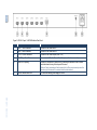
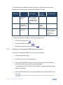
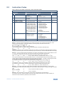
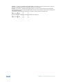
K R A ME R E LE CT R O N IC S L TD . USER MANUAL MODEL: VM-24H 2 Input 1:4 HDMI Distributor P/N: 2900-000664 Rev 3 Contents 1 Introduction 1 2 2.1 2.2 2.3 3 3.1 3.2 Getting Started Achieving the Best Performance Safety Instructions Recycling Kramer Products Overview Defining the VM-24H 2 Input 1:4 HDMI Distributor Using the IR Transmitter 2 2 3 3 4 4 7 4 Installing in a Rack 8 5 Connecting the VM-24H 6 6.1 6.2 6.3 Operating the VM-24H Controlling via RS-232 Operating the VM-24H Using the EDID Buttons 11 11 12 12 7 Technical Specifications 15 8 8.1 8.2 Communication Protocol Syntax Instruction Codes 16 16 17 9 Figures Figure 1: VM-24H 2 Input 1:4 HDMI Distributor Front Panel Figure 2: VM-24H 2 Input 1:4 HDMI Distributor Rear Panel Figure 3: Connecting the VM-24H 2 Input 1:4 HDMI Distributor Figure 4: Crossed Cable RS-232 Connection Figure 5: Straight Cable RS-232 Connection with a Null Modem Adapter 5 6 10 11 12 VM-24H – Contents i 1 Introduction Welcome to Kramer Electronics! Since 1981, Kramer Electronics has been providing a world of unique, creative, and affordable solutions to the vast range of problems that confront video, audio, presentation, and broadcasting professionals on a daily basis. In recent years, we have redesigned and upgraded most of our line, making the best even better! Our 1,000-plus different models now appear in 11 groups that are clearly defined by function: GROUP 1: Distribution Amplifiers; GROUP 2: Switchers and Routers; GROUP 3: Control Systems; GROUP 4: Format/Standards Converters; GROUP 5: Range Extenders and Repeaters; GROUP 6: Specialty AV Products; GROUP 7: Scan Converters and Scalers; GROUP 8: Cables and Connectors; GROUP 9: Room Connectivity; GROUP 10: Accessories and Rack Adapters and GROUP 11: Sierra Products. Congratulations on purchasing your Kramer VM-24H 2 Input 1:4 HDMI Distributor, which is ideal for the following typical applications: Home theater, presentation and multimedia applications Rental and staging VM-24H - Introduction 1 2 Getting Started We recommend that you: Unpack the equipment carefully and save the original box and packaging materials for possible future shipment Review the contents of this user manual i 2.1 Go to http://www.kramerelectronics.com/support/product_downloads.asp to check for up-to-date user manuals, application programs, and to check if firmware upgrades are available (where appropriate). Achieving the Best Performance To achieve the best performance: Use only good quality connection cables (we recommend Kramer highperformance, high-resolution cables) to avoid interference, deterioration in signal quality due to poor matching, and elevated noise levels (often associated with low quality cables) Do not secure the cables in tight bundles or roll the slack into tight coils Avoid interference from neighboring electrical appliances that may adversely influence signal quality Position your Kramer VM-24H away from moisture, excessive sunlight and dust ! 2 This equipment is to be used only inside a building. It may only be connected to other equipment that is installed inside a building. VM-24H - Getting Started 2.2 Safety Instructions ! 2.3 Caution: There are no operator serviceable parts inside the unit Warning: Use only the power cord that is supplied with the unit Warning: Do not open the unit. High voltages can cause electrical shock! Servicing by qualified personnel only Warning: Disconnect the power and unplug the unit from the wall before installing Recycling Kramer Products The Waste Electrical and Electronic Equipment (WEEE) Directive 2002/96/EC aims to reduce the amount of WEEE sent for disposal to landfill or incineration by requiring it to be collected and recycled. To comply with the WEEE Directive, Kramer Electronics has made arrangements with the European Advanced Recycling Network (EARN) and will cover any costs of treatment, recycling and recovery of waste Kramer Electronics branded equipment on arrival at the EARN facility. For details of Kramer’s recycling arrangements in your particular country go to our recycling pages at http://www.kramerelectronics.com/support/recycling/. VM-24H - Getting Started 3 3 Overview The VM−24H is a distribution amplifier for HDMI signals. The unit reclocks and equalizes one of two selectable input signals and distributes it to four identical outputs. The VM-24H features: A maximum data rate of 6.75Gbps ( 2.25Gbps per graphic channel) HDMI support for Deep Color, x.v.Color™, Lip Sync, CEC 3D pass-through I-EDIDPro™ Kramer Intelligent EDID Processing™, an intelligent EDID handling and processing algorithm that ensures Plug and Play operation for HDMI systems The ability to acquire the EDID from one output, from several connected outputs (auto-mix) or acquire the default EDID for fast and efficient connection of the unit Housing in a 19" 1U rack mountable enclosure Power feeding from a 100-240V AC universal switching power supply Control the VM-24H via: The front panel buttons The infrared remote control transmitter The infrared remote extension cable transmitter, see Section 3.2 RS-232 serial commands transmitted by a touch screen system, PC, or other serial controller 3.1 Defining the VM-24H 2 Input 1:4 HDMI Distributor This section defines the VM-24H. 4 VM-24H - Overview VM-24H – Overview Figure 1: VM-24H 2 Input 1:4 HDMI Distributor Front Panel # Feature Function 1 IR Receiver The red LED is illuminated when receiving signals from the Kramer infrared remote control transmitter 2 POWER Switch Illuminated switch for turning the unit ON or OFF 3 SELECT IN 1 Button Press to select source 1 and distribute this signal to the outputs 4 SELECT IN 2 Button Press to select source 2 and distribute this signal to the outputs 5 EDID READ Button Press, after pressing the EDID SELECT button, to acquire the EDID Press to show the EDID status 6 EDID SELECT Button Select the EDID mode (One Output, Auto-mix or Default) 7 OUTPUT STATUS 1-4 LEDs LEDs light when an output(s) is connected and active; LEDs flash to indicate the type of EDID acquired (see Section 6.3) or when connecting a non-HDCP display while providing HDCP content to the VM-24H 5 VM-24H - Overview 5 6 Figure 2: VM-24H 2 Input 1:4 HDMI Distributor Rear Panel # Feature Function 8 INPUT 1 HDMI Connector Connects to the HDMI source 1 9 INPUT 2 HDMI Connector Connects to the HDMI source 2 10 OUTPUT HDMI Connectors Connects to the HDMI acceptor (from 1 to 4) 11 RS-232 9-pin D-sub Port Connects to the PC or the Remote Controller (via a null modem connection) 12 REMOTE IR Opening Connects to an external IR receiver unit for controlling the machine via an IR remote controller instead of using the front panel IR receiver Optional. Can be used instead of the front panel (built-in) IR receiver to remotely control the machine (only if the internal IR connection cable has been installed) 13 Power Connector with Fuse AC connector enabling power supply to the unit VM-24H – Overview 6 VM-24H - Overview 3.2 Using the IR Transmitter You can use the RC-IR3 IR transmitter to control the machine via the built-in IR receiver on the front panel or, instead, via an optional external IR receiver (Model: C-A35M/IRR-50). The external IR receiver can be located up to 15 meters away from the machine. This distance can be extended to up to 60 meters when used with three extension cables (Model: C-A35M/A35F-50). Before using the external IR receiver, be sure to arrange for your Kramer dealer to insert the internal IR connection cable (P/N: 505-70434010-S) with the 3.5mm connector that fits into the REMOTE IR opening on the rear panel. Connect the external IR receiver to the REMOTE IR 3.5mm connector. VM-24H - Overview 7 4 Installing in a Rack This section provides instructions for rack mounting the unit. 8 VM-24H - Installing in a Rack 5 Connecting the VM-24H i Always switch off the power to each device before connecting it to your VM-24H. After connecting your VM-24H, connect its power and then switch on the power to each device. To connect the VM-24H, as illustrated in the example in Figure 3, do the following: 1. Connect the two HDMI sources, for example, a DVD player and a set top box, to the INPUT 1 and INPUT 2 connectors, respectively. 2. Connect the HDMI OUTPUT connectors to up to 4 HDMI acceptors, using Kramer HDMI copper cables. In this example, connect the: OUTPUT 1 connector to acceptor 1 (for example, a plasma display) OUTPUT 2 connector to acceptor 2 (for example, an LCD TV) OUTPUT 3 connector to acceptor 3 (for example, an LCD TV) OUTPUT 4 connector to acceptor 4 (for example, a plasma display) Up to four outputs can be connected. Not all outputs need to be connected. 3. If required, connect a PC and/or controller to the RS-232 port (see Section 6.1). 4. Connect the power cord to the mains electricity (not shown in Figure 3). 5. If required, acquire the EDID (see Section 6.3). VM-24H - Connecting the VM-24H 9 Figure 3: Connecting the VM-24H 2 Input 1:4 HDMI Distributor 10 VM-24H - Connecting the VM-24H 6 Operating the VM-24H This section describes how to: 6.1 Control the VM-24H via RS-232, see Section 6.1 Operate the VM-24H, see Section 6.2 Use the EDID button, see Section 6.3 Controlling via RS-232 You can connect to the unit via a crossed RS-232 connection, using for example, a PC. A crossed cable or null-modem is required as shown in method A and B respectively. If a shielded cable is used, connect the shield to pin 5. Method A (Figure 4)—Connect the RS-232 9-pin D-sub port on the unit via a crossed cable (only pin 2 to pin 3, pin 3 to pin 2, and pin 5 to pin 5 need be connected) to the RS-232 9-pin D-sub port on the PC. Note: There is no need to connect any other pins. 9 8 7 6 5 4 3 2 1 9 8 7 6 5 4 3 2 PC 1 Figure 4: Crossed Cable RS-232 Connection Hardware flow control is not required for this unit. In the rare case where a controller requires hardware flow control, short pin 1 to 7 and 8, and pin 4 to 6 on the controller side. Method B (Figure 5)—Connect the RS-232 9-pin D-sub port on the unit via a straight (flat) cable to the null-modem adapter, and connect the null-modem adapter to the RS-232 9-pin D-sub port on the PC. The straight cable usually contains all nine wires for a full connection of the D-sub connector. Because the null-modem adapter (which already includes the flow control jumpering described VM-24H - Operating the VM-24H 11 in Method A above) only requires pins 2, 3 and 5 to be connected, you are free to decide whether to connect only these 3 pins or all 9 pins. 9 8 7 6 5 4 3 2 1 Null-Modem Adapter to PC Figure 5: Straight Cable RS-232 Connection with a Null Modem Adapter 6.2 Operating the VM-24H To operate the VM-24H: 1. Turn ON the POWER. 2. Select the desired input. 3. If required, press the EDID button to acquire or change the EDID data (see Section 6.3). 6.3 Using the EDID Buttons You can acquire the EDID from: One Output (the selected output LED flashes) The Default EDID (all the output LEDs flash) Several Connected Outputs, the Auto-mix Mode (the output LEDs flash in sequence) The EDID acquired is a weighted average of all the connected outputs. For example, if several displays with different resolutions are connected to the outputs, the acquired EDID supports all the resolutions, as well as other parameters included in the EDID. 12 VM-24H - Operating the VM-24H To cycle between the different modes (One Output, Default and Auto-mix), as defined in the following table, press the EDID SELECT button. Current EDID Mode Appearance To cycle to the Default EDID One Output The selected output LED flashes Press the EDID SELECT button once again after selecting output 4. The output LEDS flash Default The output LEDs flash simultaneously Auto-mix All the output LEDs light To cycle to the Automix EDID To cycle to the One output EDID Press the EDID SELECT button once Press the EDID SELECT button to select the required output. The selected output flashes To acquire or change the EDID of a new output display from: 6.3.1 One output, see section 6.3.1 The default EDID, see section 6.3.2 Several connected outputs, see section 6.3.3 Acquiring / Changing the EDID from One Output To acquire or change the EDID of one of the output displays: 1. Connect the power supply. 2. Connect the new output display device. 3. Press the EDID SELECT button, enter the One output mode as defined in the previous table, and set to the connected output. The appropriate OUTPUT STATUS LED flashes, indicating that that output channel is selected. 4. Press the EDID READ button to copy the EDID of the selected OUTPUT to the inputs. If you want to cancel the EDID modification, wait for a few seconds without touching any button VM-24H - Operating the VM-24H 13 5. While the EDID is being copied, the EDID SELECT and READ buttons illuminate. The new EDID is copied when both buttons no longer illuminate. 6.3.2 Acquiring the Default EDID To reset to the default EDID (the factory-default programmed into the VM-24H before it is shipped), do the following: 1. Connect the power supply. 2. Press the EDID SELECT button and set it to the Default EDID mode. All the OUTPUT STATUS LEDs flash simultaneously. 3. Press the EDID READ button to copy the default EDID to the inputs. While the EDID is being copied, the EDID SELECT and READ buttons illuminate. The new EDID is copied when both buttons no longer illuminate. 6.3.3 Acquiring the Auto-Mix EDID from the Connected Outputs To acquire the Auto-mix EDID: The EDID acquired is a weighted average of all the connected outputs. For example, if several displays with different resolutions are connected to the outputs, the acquired EDID supports all the resolutions, as well as other parameters included in the EDID. 1. Connect the power supply. 2. Connect the desired output display devices. 3. Enter the Auto-mix mode as defined in the preceding table. All the OUTPUT STATUS LEDs light. 4. Press the READ button to copy the EDID of the selected OUTPUT to the inputs. While the EDID is being copied, the EDID SELECT and READ buttons illuminate. The new EDID is copied when both buttons no longer illuminate. 14 VM-24H - Operating the VM-24H 7 Technical Specifications INPUTS: 2 HDMI connectors OUTPUTS: 4 HDMI connectors MAX. DATA RATE: 6.75Gbps ( 2.25Gbps per graphic channel) COMPLIANCE WITH HDMI STANDARD: Supports HDMI and HDCP CONTROLS: EDID SELECT, EDID READ, IN 1, IN 2 buttons, RS-232, IR INDICATOR LEDs: OUTPUT STATUS LEDs POWER CONSUMPTION: 100-240V AC 50/60Hz, 16VA OPERATING TEMPERATURE: 0° to +40°C (32° to 104°F) STORAGE TEMPERATURE: -40° to +70°C (-40° to 158°F) HUMIDITY: 10% to 90%, RHL non-condensing DIMENSIONS: 19" x 7" x 1U W, D, H rack mountable WEIGHT: 2.5kg (5.5lbs) approx. ACCESSORIES: Power cord, rack “ears”, null-modem adapter, Windows®based control software, infrared remote control transmitter OPTIONS: External remote IR receiver cable (P/N: C-A35M/IRR-50) Specifications are subject to change without notice at http://www.kramerelectronics.com VM-24H - Technical Specifications 15 8 Communication Protocol The VM-24H is compatible with Kramer’s Protocol 2000. This RS-232/RS-485 communication protocol uses four bytes of information as defined below. For RS-232, a null-modem connection between the machine and controller is used. The default data rate is 9600 baud, with no parity, 8 data bits and 1 stop bit. Note: Compatibility with Kramer’s Protocol 2000 does not mean that a machine uses all of the commands below. Each machine uses a sub-set of Protocol 2000, according to its needs. 8.1 Syntax MSB LSB 1st Byte 0 7 DESTINATION D 6 INSTRUCTION N2 2 N5 5 N4 4 N3 3 2nd Byte 1 7 I6 6 I5 5 I4 4 INPUT I3 3 3rd Byte 1 7 O6 6 O5 5 O4 4 OUTPUT O3 3 4th Byte 1 7 OVR 6 X 5 M4 4 M3 3 N1 1 N0 0 I2 2 I1 1 I0 0 O2 2 O1 1 O0 0 MACHINE NUMBER M2 M1 2 1 M0 0 Bit 7 – Defined as 0 D – DESTINATION: 0 – Sends information to the switchers (from the PC) 1 – Sends information to the PC (from the switcher) N5…N0 – INSTRUCTION The 6-bit INSTRUCTION defines the function performed by the switcher(s). If a function is performed using the machine’s keyboard, these bits are set with the INSTRUCTION NO. performed. The instruction codes are defined according to the table below (INSTRUCTION NO. is the value set in N5…N0). 1st Byte: Bit 7 – Defined as 1 I6…I0 – INPUT When switching (i.e. instruction codes 1 and 2), the 7-bit INPUT is set as the input number to be switched. If switching is done using the machine’s front panel, these bits are set with the INPUT NUMBER switched. For other operations, these bits are defined according to the table. 2nd Byte: Bit 7 – Defined as 1 O6…O0 – OUTPUT When switching (i.e. instruction codes 1 and 2), the 7-bit OUTPUT is set as the output number to be switched. If switching is done using the machine’s front panel, these bits are set with the OUTPUT NUMBER switched. For other operations, these bits are defined according to the table. 3rd Byte: Bit 7 – Defined as 1 Bit 5 – Don’t care OVR – Machine number override M4…M0 – MACHINE NUMBER This byte is used to address machines in a system by their machine numbers. When several machines are controlled from a single serial port, they are usually configured together and each machine has an individual machine number. If the OVR bit is set, then all machine numbers accept (implement) the command and the addressed machine replies. When a single machine is controlled over the serial port, always set M4…M0 to 1, and make sure that the machine itself is configured as MACHINE NUMBER = 1. 4th Byte: 16 VM-24H - Communication Protocol 8.2 Instruction Codes All the values in the table are decimal, unless otherwise stated Instruction Codes for Protocol 2000 Instruction Definition for Specific Instruction # Description Input Output 1 SWITCH VIDEO LOCK FRONT PANEL Set equal to video output that is switched (0 = to all the outputs) 0 2, 15 30 31 REQUEST WHETHER PANEL IS LOCKED IDENTIFY MACHINE Set equal to video input that is switched (0 = disconnect) Unlock panel Lock panel 0 0 16 1 – Video machine name 2 – Audio machine name 3 – Video software version 4 – Audio software version 5 – RS-422 controller name 6 – RS-422 controller version 7 – Remote control name 8 – Remote software version 9 – Protocol 2000 revision 10 – Control data machine name 11 – Control data software version 1 – Number of inputs 2 – Number of outputs 3 – Number of setups For names: 0 – Request first 4 digits 1 – Request first suffix 2 – Request second suffix 3 – Request third suffix 10 – Request first prefix 11 – Request second prefix 12 – Request third prefix 13 61 62 DEFINE MACHINE 63 EXTENDED DATA 7 MSBs for INPUT data Notes 2 For versions: 0 – main board or the number of external board 1 – For video 2 – For audio 3 – For SDI 4 – For remote panel 5 – For RS-422 controller 6 – For control data 7 MSBs for OUTPUT data 14 20 NOTES on the above table: NOTE 2 – These are bi-directional definitions. If the switcher receives the code, it performs the instruction. If the instruction is performed (due to a keystroke operation on the front panel), then these codes are sent. For example, if the PC sends HEX code: 01 85 88 83 then the switcher (machine 3) switches input 5 to output 8. If the user switches input 1 to output 7 using the front panel buttons, the switcher sends HEX code: 41 81 87 83 to the PC. When the PC sends one of the commands in this group to the switcher, if the instruction is valid, the switcher replies by sending the same four bytes to the PC that it received (except for the first byte, where the DESTINATION bit is set high). NOTE 13 – This is a request to identify the switcher/s in the system. If the OUTPUT is set as 0, and the INPUT is set as 1, 2, 5 or 7, the machine sends its name. The reply is the decimal value of the INPUT and OUTPUT. For example, for a 2216, the reply to the request to send the audio machine name is HEX code: 7D 96 90 81 (i.e. 128dec+ 22dec for 2nd byte, and 128dec+ 16dec for 3rd byte). If the request for identification is sent with the INPUT set as 3 or 4, the appropriate machine sends its software version number. Again, the reply would be the decimal value of the INPUT and OUTPUT - the INPUT representing the number in front of the decimal point, and the OUTPUT representing the number after it. For example, for version 3.5, the reply to the request to send the version number would be HEX code: 7D 83 85 81 (i.e. 128dec+ 3dec for 2nd byte, 128dec+ 5dec for 3rd byte). If the OUTPUT is set as 1, then the ASCII coding of the lettering following the machine’s name is sent. For example, for the VS-7588YC, the reply to the request to send the first suffix would be HEX code: 7D D9 C3 81 (i.e. 128dec+ ASCII for “Y”; 128dec+ ASCII for “C”). NOTE 14 – The number of inputs and outputs refers to the specific machine being addressed, not to the system. For example, if six 16x16 matrices are configured to make a 48x32 system (48 inputs, 32 outputs), the reply to the HEX code: 3E 82 81 82 (i.e. request the number of outputs) would be HEX code: 7E 82 90 82 (i.e. 16 outputs). NOTE 15 – When the OVR bit (4th byte) is set, then the video commands have universal meaning. For example, instruction 1 (SWITCH VIDEO) causes all units (including audio, data, etc.) to switch. Similarly, if a machine is in FOLLOW mode, it performs any video instruction. VM-24H - Communication Protocol 17 NOTE 16 – The reply to the REQUEST WHETHER PANEL IS LOCKED is the same as in NOTE 4 above, except that OUTPUT is assigned with the value 0 if the panel is unlocked, or 1 if it is locked. NOTE 20 – When data (i.e. the INPUT and/or OUTPUT bytes) of more than 7 bits is required, instruction 63 is sent before sending the instruction needing the additional bits. The data in this instruction then becomes the most significant bits of that next instruction. For example, to set the audio gain (instruction 22) of output 3 to 681dec (2A9hex), send HEX code: 3F 80 85 81 followed by HEX code: 16 83 A9 81. To set the audio gain of output 6 to 10013dec (271Dhex), send HEX code: 3F 80 CE 81 followed by HEX code: 16 86 9D 81. 18 VM-24H - Communication Protocol For the latest information on our products and a list of Kramer distributors, visit our Web site where updates to this user manual may be found. We welcome your questions, comments, and feedback. Web site: www.kramerelectronics.com E-mail: [email protected] ! P/N: SAFETY WARNING Disconnect the unit from the power supply before opening and servicing 2900- 000664 Rev: 3