1
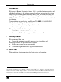
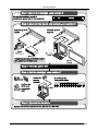
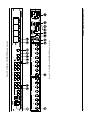
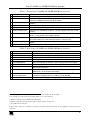
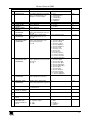
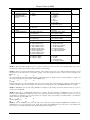
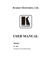
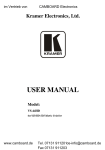
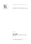
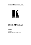
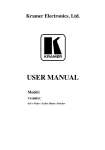
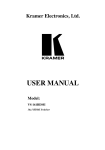
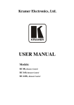
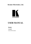
Kramer Electronics, Ltd.
USER MANUAL
Model:
VS-88HD
8x8 SD/HD-SDI Matrix Switcher
Contents
Contents
1
2
Introduction
Getting Started
Quick Start
1
3
4
5
6
Overview
Your VS-88HD 8x8 SD/HD-SDI Matrix Switcher
Installing on a Rack
Connecting Your VS-88HD 8x8 SD/HD-SDI Matrix Switcher
3
3
6
7
6.1.1
Setting the Machine # Dipswitches
6.2
6.3
Controlling via RS-232 (for example, using a PC)
Controlling via the RS-485 Port
7
Operating the VS-88HD
Switching OUT-IN Combinations
Confirming Settings
11
11
7.2.1
7.2.2
Toggling between the AT ONCE and CONFIRM Modes
Confirming a Switching Action
12
12
7.3
Storing/Recalling Input/Output Configurations
12
7.3.1
7.3.2
8
9
10
Storing an Input/Output Configuration
Recalling an Input/Output Configuration
Technical Specifications
Table of Hex Codes for Serial Communication
Kramer Protocol 2000
12
13
13
14
15
2.1
6.1
7.1
7.2
Dipswitch Settings
1
1
8
9
9
10
11
Figures
Figure 1: VS-88HD 8x8 SD/HD-SDI Matrix Switcher
Figure 2: Connecting the VS-88HD 8x8 SD/HD-SDI Matrix Switcher
Figure 3: Dipswitches
Figure 4: Connecting a PC without using a Null-modem Adapter
Figure 5: Controlling via RS-485 (for example, using an RC-3000)
4
8
8
9
10
Tables
Table 1: Front Panel VS-88HD 8x8 SD/HD-SDI Matrix Switcher
Table 2: Rear Panel VS-88HD 8x8 SD/HD-SDI Matrix Switcher
Table 3: Machine # Dipswitch Settings
Table 4: Technical Specifications of the VS-88HD 8x8 SD/HD-SDI Matrix Switcher
Table 5: VS-88HD Hex Codes for Switching via RS-232/RS-485
Table 6: Protocol Definitions
Table 7: Instruction Codes for Protocol 2000
5
5
9
13
14
15
16
i
Introduction
1
Introduction
Welcome to Kramer Electronics (since 1981): a world of unique, creative and
affordable solutions to the infinite range of problems that confront the video,
audio and presentation professional on a daily basis. In recent years, we have
redesigned and upgraded most of our line, making the best even better! Our
500-plus different models now appear in 8 Groups1, which are clearly defined
by function.
Congratulations on purchasing your Kramer VS-88HD 8x8 SD/HD-SDI
Matrix Switcher. This product is ideal for:
Professional broadcasting and production studios
Presentation applications
The package includes the following items:
VS-88HD 8x8 SD/HD-SDI Matrix Switcher
Power cord, Null-modem adapter and this user manual2
2
Getting Started
We recommend that you:
Unpack the equipment carefully and save the original box and
packaging materials for possible future shipment
Review the contents of this user manual
Use Kramer high performance high resolution cables3
2.1 Quick Start
This quick start chart summarizes the basic setup and operation:
1 GROUP 1: Distribution Amplifiers; GROUP 2: Video and Audio Switchers, Matrix Switchers and Controllers; GROUP 3:
Video, Audio, VGA/XGA Processors; GROUP 4: Interfaces and Sync Processors; GROUP 5: Twisted Pair Interfaces;
GROUP 6: Accessories and Rack Adapters; GROUP 7: Scan Converters and Scalers; and GROUP 8: Cables and Connectors
2 Download up-to-date Kramer user manuals from the Internet at this URL: http://www.kramerelectronics.com
3 The complete list of Kramer cables is on our Web site at http://www.kramerelectronics.com
1
Getting Started
2
KRAMER: SIMPLE CREATIVE TECHNOLOGY
Overview
3
Overview
The VS-88HD is an HDTV compatible high performance matrix switcher for
HD-SDI and SDI digital video signals. It lets you simultaneously route any of
the eight inputs to any or all of the eight outputs. Switching during the
vertical interval ensures glitch-free switching with genlocked sources. In
particular, the VS-88HD features:
Input and output signals on BNC connectors
A looping analog sync input with selectable sync signal termination
Switching synchronization, letting you synchronize to either the
external reference or incoming video
Automatic reclocking and equalization on each input
Each input button on the front panel automatically lights up when
the VS-88HD detects a video signal on that input
Switching according to the Bi-level or Tri-level Genlock input
The storing and recalling of setups
A Take button for the execution of multiple switches all at once
A 7-segment display
The VS-88HD, which is housed in a 19" 1U rack mountable enclosure, and is
fed from a 90-240 VAC universal switching power supply, can be controlled
via the:
Front panel buttons
Remotely, by RS-232 or RS-485 serial commands transmitted by a
touch screen system, PC, or other serial controller
To achieve the best performance:
Connect only good quality connection cables, thus avoiding
interference, deterioration in signal quality due to poor matching, and
elevated noise levels (often associated with low quality cables)
Avoid interference from neighboring electrical appliances that may
adversely influence signal quality and position your Kramer VS-88HD
away from moisture, excessive sunlight and dust
4
Your VS-88HD 8x8 SD/HD-SDI Matrix Switcher
Figure 1, Table 1, and Table 2 define the VS-88HD 8x8 SD/HD-SDI Matrix
Switcher.
3
4
Figure 1: VS-88HD 8x8 SD/HD-SDI Matrix Switcher
Your VS-88HD 8x8 SD/HD-SDI Matrix Switcher
KRAMER: SIMPLE CREATIVE TECHNOLOGY
Your VS-88HD 8x8 SD/HD-SDI Matrix Switcher
Table 1: Front Panel VS-88HD 8x8 SD/HD-SDI Matrix Switcher
#
Feature
Function
1
2
POWER Switch
OFF Button
3
ALL Button
4
5
6
IN SELECT Buttons
OUT SELECT Buttons
STO (STORE) Button
7
RCL (RECALL) Button
8
TAKE Button
9
7-segment Display
Illuminated switch for turning the unit ON or OFF
An OFF-OUT combination disconnects that output from the inputs; an
OFF-ALL combination disconnects all the outputs
Pressing ALL followed by an INPUT button, connects that input to all
1
outputs
Select the input to switch to the output
Select the output to which the input is switched
Pressing STO followed by an INPUT / OUTPUT button stores the current
2
setting
Pressing the RCL button and the corresponding INPUT / OUTPUT key
recalls a setup from the non-volatile memory
3
Pressing TAKE toggles the mode between the CONFIRM mode and the
AT ONCE mode (user confirmation per action is unnecessary)
Displays the selected input switched to the output (marked above each
input)
Lights when the input signal complies with the SDI standard
10 INPUT STATUS LEDs
Table 2: Rear Panel VS-88HD 8x8 SD/HD-SDI Matrix Switcher
#
Feature
Function
11
12
13
14
15
INPUT BNC Connectors
OUTPUT BNC Connectors
LOOP BNC Connector
SYNC BNC Connector
Connect to the serial digital video sources
Connect to the serial digital video acceptors
Connect to the Genlock connector of the next unit in the line
Connect to the Genlock source
75 TERM Button
16 RS-232 IN DB 9F Port
17 RS-232 OUT DB 9M Port
18 MACHINE # Dipswitches
19 RS-485 Detachable
Terminal Block Port
20 Power Connector with Fuse
Press to terminate the Genlock source (75 ) or release for looping4
Connects to the PC or the Remote Controller5
Connects to the RS-232 IN DB 9F port of the next unit in the
daisy-chain connection
Dipswitches for setup of the unit (1, 2, 3 and 4 are for setting the
Machine #; 8 is for RS 485 Termination)
The SYNC and the G PINs are for vertical sync and the ground6
connection respectively; pins A (+) and B (-) are for RS-485
AC connector enabling power supply to the unit
1 For example, press ALL and then Input button # 2 to connect input # 2 to all the outputs
2 For example, press STO and then the Output button # 3 to store in Setup # 3
3 When in Confirm mode, the TAKE button illuminates
4 Push in to terminate the input. Release when the input extends to another unit
5 Via a null-modem connection
6 The ground connection is sometimes connected to the shield of the RS-485 cable. In most applications, the ground is not
connected
5
Installing on a Rack
5
Installing on a Rack
This section describes what to do before installing on a rack and how to rack
mount.
6
KRAMER: SIMPLE CREATIVE TECHNOLOGY
Connecting Your VS-88HD 8x8 SD/HD-SDI Matrix Switcher
6
Connecting Your VS-88HD 8x8 SD/HD-SDI Matrix Switcher
You can use your VS-88HD to switch one of the eight standard definition /
high definition SDI inputs to any or all of the eight standard definition / high
definition SDI outputs, as the example in Figure 2 shows.
To connect the VS-88HD 8x8 SD/HD-SDI Matrix Switcher, do the following1:
1. Connect up to eight SDI sources to the SDI INPUT BNC connectors (for
example, an HD/SD SDI camera to input 1 and an SDI player to input 8).
2. Connect the SDI OUTPUT BNC connectors to up to2 eight SDI
acceptors (for example, output 1 to a non linear editor, and output 8 to an HD
SDI display).
3. Set the dipswitches (see section 6.1).
As an option3, connect:
A Genlock source to the SYNC BNC connector
The LOOP BNC connector to the GENLOCK connector of the next
unit in the line, and release the TERM button for looping4
4.
5.
Connect a PC and/or controller (if required), to the:
RS-232 port (see section 6.2), and/or
RS-485 port (see section 6.3), and/or
6.
Connect the power cord5.
1 Switch OFF the power on each device before connecting it to your VS-88HD. After connecting your VS-88HD, switch on
its power and then switch on the power on each device
2 When only one output is required, connect that output, and leave the other outputs unconnected
3 Not illustrated in Figure 2
4 Pushed in terminates the input. Release when the input extends to another unit
5 We recommend that you use only the power cord that is supplied with this machine
7
Connecting Your VS-88HD 8x8 SD/HD-SDI Matrix Switcher
Figure 2: Connecting the VS-88HD 8x8 SD/HD-SDI Matrix Switcher
6.1 Dipswitch Settings
By default, all dipswitches are set to OFF. Figure 3 illustrates the VS-88HD
dipswitches:
Figure 3: Dipswitches
8
KRAMER: SIMPLE CREATIVE TECHNOLOGY
Connecting Your VS-88HD 8x8 SD/HD-SDI Matrix Switcher
6.1.1
Setting the Machine # Dipswitches
The Machine # determines the position of a VS-88HD unit, specifying which
VS-88HD unit is being controlled when several VS-88HD units connect to a
PC or serial controller. Set the Machine # on a VS-88HD unit via SETUP
DIPS 1, 2, 3 and 4, according to Table 3.
When using a standalone VS-88HD unit, set the Machine # to 1. When
connecting more than one VS-88HD unit, set the first machine (the Master)
that is closest to the PC, as Machine # 1 (dipswitches are set to OFF).
Table 3: Machine # Dipswitch Settings
Mach. #
1
2
3
4
5
6
7
8
DIP 1
DIP 2
DIP 3
DIP 4
OFF
ON
OFF
ON
OFF
ON
OFF
ON
ON
OFF
OFF
ON
ON
OFF
OFF
ON
ON
ON
ON
OFF
OFF
OFF
OFF
ON
ON
ON
ON
ON
ON
ON
ON
OFF
6.2 Controlling via RS-232 (for example, using a PC)
To connect a PC to the VS-88HD unit, using the Null-modem adapter
provided with the machine (recommended):
Connect the RS-232 DB9 rear panel port on the VS-88HD unit to
the Null-modem adapter and connect the Null-modem adapter with a 9
wire flat cable to the RS-232 DB9 port on your PC
To connect a PC to the VS-88HD unit, without using a Null-modem adapter:
Connect the RS-232 DB9 port on your PC to the RS-232 DB9 rear
panel port on the VS-88HD unit, as Figure 4 illustrates
Figure 4: Connecting a PC without using a Null-modem Adapter
9
Connecting Your VS-88HD 8x8 SD/HD-SDI Matrix Switcher
6.3 Controlling via the RS-485 Port
To cascade up to eight individual VS-88HD units, via RS-485 (with control
via a Master Programmable Remote Control system such as the Kramer
RC-3000), as Figure 5 illustrates, do the following:
1. Connect the “A” (+) and “B” (-) PINS on the RS-485 terminal block port
of the RC-3000 to the “A” (+) and “B” (-) PINS, respectively, on each of the
eight VS-88HD units. (If using shielded twisted pair cable, the shield is
usually connected to the “G” (Ground) PIN of the first unit).
2. Set the first VS-88HD unit as MACHINE # 1 and the following seven
VS-88HD units as MACHINE # 2 to MACHINE # 8, according to Table 3.
Figure 5: Controlling via RS-485 (for example, using an RC-3000)
10
KRAMER: SIMPLE CREATIVE TECHNOLOGY
Operating the VS-88HD
7
Operating the VS-88HD
You can operate your VS-88HD via the front panel buttons, and/or
RS-232/RS-485 serial commands transmitted by a PC, touch screen system,
or other serial controller.
7.1 Switching OUT-IN Combinations
To switch an input to an output via the front panel buttons, in the AT ONCE
mode (see section 7.2), do the following:
1. Press an OUT SELECT button1 or the ALL button.
The selected OUT SELECT button illuminates, as does the 7-segment display.
2. Press an IN SELECT button1 or the OFF button2.
The selected input switches to the selected output, and that IN SELECT
button illuminates. The digits displayed in the 7-segment display change as
appropriate.
7.2 Confirming Settings
Choose to work in the AT ONCE or the CONFIRM mode (see section 0).
When the VS-88HD operates in the AT ONCE mode, pressing an OUT-IN
combination implements the switch immediately. In the CONFIRM mode,
the TAKE button must be pressed to authorize the switch.
In the AT ONCE mode, you save time as execution is immediate and actions
require no user confirmation. However, no protection is offered against
changing an action in error.
In the CONFIRM mode:
You can key-in several actions and then confirm them by pressing
the “TAKE” button, to simultaneously activate the multiple switches
Every action requires user confirmation, protecting against
erroneous switching
Execution is delayed until the user confirms the action
1 From 1 to 8
2 For immediate switching
11
Operating the VS-88HD
7.2.1
Toggling between the AT ONCE and CONFIRM Modes
To toggle between the AT ONCE and CONFIRM modes, do the following:
1. Press the dim TAKE button to toggle from the AT ONCE mode (in
which the TAKE button is dim) to the CONFIRM mode (in which the TAKE
button illuminates).
Actions now require user confirmation and the TAKE button illuminates.
2. Press the illuminated TAKE button to toggle from the CONFIRM mode
back to the AT ONCE mode.
Actions no longer require user confirmation and the TAKE button no longer
illuminates.
7.2.2
Confirming a Switching Action
To confirm a switching action (in CONFIRM mode- when the TAKE button
is illuminated), do the following:
1. Press an OUT-IN combination.
The 7-segment Display blinks1.
2. Press the TAKE button to confirm the action.
The 7-segment Display no longer blinks. The TAKE button illuminates.
To confirm several actions (in CONFIRM mode), do the following:
1. Press each OUT-IN combination in sequence.
The 7-segment Display blinks.
2. Press the TAKE button to confirm all the actions.
The 7-segment Display no longer blinks. The TAKE button illuminates.
7.3 Storing/Recalling Input/Output Configurations
You can store and recall up to eight setup configurations using the eight IN
SELECT buttons and the eight OUT SELECT buttons.
7.3.1
Storing an Input/Output Configuration
To store the current status in memory, do the following:
1. Press the STO button.
The STO button illuminates.
2. Press one of the IN / OUT SELECT buttons (this will be the setup # in
which the current status is stored).
The selected IN / OUT SELECT button illuminates in blue. The memory
stores the data at that reference.
1 The timeout lasts for 10 seconds
12
KRAMER: SIMPLE CREATIVE TECHNOLOGY
Technical Specifications
7.3.2
Recalling an Input/Output Configuration
To recall an input/output configuration, do the following:
1. Press the RCL button.
The RCL button illuminates.
2. Press the appropriate IN / OUT SELECT button (the button #
corresponding to the setup #). That setup configuration will blink in the
7-segment Display.
The memory recalls the stored data from that reference.
After pressing the same memory location the second time, the settings will
take effect.
8
Technical Specifications
Table 4 includes the technical specifications:
1
Table 4: Technical Specifications of the VS-88HD 8x8 SD/HD-SDI Matrix Switcher
INPUTS:
OUTPUTS:
MAX. OUTPUT LEVEL:
DATA RATE:
CONTROLS:
POWER SOURCE:
DIMENSIONS:
WEIGHT:
ACCESSORIES:
8 SDI SMPTE-259M, 292M, 344M serial video, 75 ohms on BNC connectors
1 GENLOCK 75 / Hi-Z on a BNC connector
8 equalized and reclocked SMPTE-259M, 292M, 344M outputs 75 ohms on
BNC connectors
1 Looped GENLOCK 75 / Hi-Z on a BNC connector
800mVpp /75 ohms
Up to 1.485Gbps
Front-panel, RS-232; and RS-485
Universal, 90-240VAC, 50/60Hz 18VA
19 inch (W), 7 inch (D), 1U (H) rack mountable
2.6 kg. (5.7 lbs.) approx.
Power cord, Null-modem Adapter
1 Specifications are subject to change without notice
13
Table of Hex Codes for Serial Communication
9
Table of Hex Codes for Serial Communication
Table 5 lists the Hex values for a single machine (MACHINE # 1):
Table 5: VS-88HD Hex Codes for Switching via RS-232/RS-485
OUT 1
OUT 2
OUT 3
OUT 4
OUT 5
OUT 6
OUT 7
OUT 8
IN 1
IN 2
IN 3
IN 4
IN 5
IN 6
IN
IN 8
14
KRAMER: SIMPLE CREATIVE TECHNOLOGY
Kramer Protocol 2000
10 Kramer Protocol 2000
The VS-88HD is compatible with Kramer’s Protocol 2000 (version 0.48)
(below). This RS-232/RS-485 communication protocol uses four bytes of
information as defined below. For RS-232, a null-modem connection between
the machine and controller is used. The default data rate is 9600 baud, with
no parity, 8 data bits and 1 stop bit.
Table 6: Protocol Definitions
MSB
LSB
DESTINATION
0
7
1st byte
D
6
INSTRUCTION
N5
5
N4
4
N3
3
N2
2
N1
1
N0
0
I5
5
I4
4
I3
3
I2
2
I1
1
I0
0
O6
6
O5
5
O4
4
O3
3
O2
2
O1
1
O0
0
OVR
6
X
5
M2
2
M1
1
M0
0
INPUT
1
7
I6
6
2nd byte
OUTPUT
1
7
3rd byte
MACHINE NUMBER
1
7
M4
4
M3
3
4th byte
1st BYTE:
Bit 7 – Defined as 0.
D – “ DESTINATION” :
0 - for sending information to the switchers (from the PC);
1 - for sending to the PC (from the switcher).
N5…N0 – “ INSTRUCTION”
The function that is to be performed by the switcher(s) is defined by the INSTRUCTION (6 bits). Similarly, if a function is
performed via the machine’s keyboard, then these bits are set with the INSTRUCTION NO., which was performed. The
instruction codes are defined according to the table below (INSTRUCTION NO. is the value to be set for N5…N0).
2nd BYTE:
Bit 7 – Defined as 1.
I6…I0 – “ INPUT” .
When switching (ie. instruction codes 1 and 2), the INPUT (7 bits) is set as the input number which is to be switched.
Similarly, if switching is done via the machine’s front-panel, then these bits are set with the INPUT NUMBER which was
switched. For other operations, these bits are defined according to the table.
3rd BYTE:
Bit 7 – Defined as 1.
O6…O0 – “ OUTPUT” .
When switching (ie. instruction codes 1 and 2), the OUTPUT (7 bits) is set as the output number which is to be switched.
Similarly, if switching is done via the machine’s front-panel, then these bits are set with the OUTPUT NUMBER which was
switched. For other operations, these bits are defined according to the table.
4th BYTE:
Bit 7 – Defined as 1.
Bit 5 – Don’t care.
OVR – Machine number override.
M4…M0 – MACHINE NUMBER.
Used to address machines in a system via their machine numbers. When several machines are controlled from a single serial
port, they are usually configured together with each machine having an individual machine number. If the OVR bit is set, then
all machine numbers will accept (implement) the command, and the addressed machine will reply.
For a single machine controlled via the serial port, always set M4…M0 = 1, and make sure that the machine itself is
configured as MACHINE NUMBER = 1.
15
Kramer Protocol 2000
Table 7: Instruction Codes for Protocol 2000
Note: All values in the table are decimal, unless otherwise stated.
INSTRUCTION
DEFINITION FOR SPECIFIC INSTRUCTION
#
DESCRIPTION
INPUT
0
1
RESET VIDEO
SWITCH VIDEO
2
SWITCH AUDIO
3
STORE VIDEO
STATUS
RECALL VIDEO
STATUS
REQUEST STATUS
OF A VIDEO OUTPUT
REQUEST STATUS
OF AN AUDIO
OUTPUT
VIS SOURCE
4
5
6
7
0
Set equal to video input which is to
be switched
(0 = disconnect)
Set equal to audio input which is to
be switched
(0 = disconnect)
Set as SETUP #
Set as SETUP #
Set as SETUP #
Set as SETUP #
0 - for video
1
1 - for audio
2 - for VGA and DVI
13
14
15
16
2, 3, 15
4, 3
4, 3
2
VIDEO / AUDIO TYPE
SETTING
12
2, 3, 15
0 - audio-follow-video
1 - audio breakaway
0 - FOLLOW mode
1 - Normal mode
0 - CV
4 - SDI
1 - YC
5 - CV+YC
2 - YUV
6 - VGA scaler
3 - RGBS
7 - DVI
O0=0 – Unbalanced audio
O0=1 – Balanced audio
O1=0 – Digital audio
O1=1 – Analog audio
O4=0, O3=0, O2=0-Mono
O4=0, O3=0,O2=1-Stereo
1 - 640X480
2 - 800X600
3 - 1024X768
0 - VIS source
1 - Input # or output # of source
2 - Vertical sync freq (Hz)
0 - Request audio breakaway
setting
1 - Request “FOLLOW” setting
0 - for video
1 - for audio
2 - for VGA
Set equal to highest machine
address
0
9
REQUEST
BREAKAWAY
SETTING
REQUEST VIDEO /
AUDIO TYPE
SETTING
SET HIGHEST
MACHINE ADDRESS
REQUEST HIGHEST
MACHINE ADDRESS
REQUEST WHETHER
SETUP IS DEFINED /
VALID INPUT IS
DETECTED
2
2, 5, 17, 18
0
11
Equal to output number whose
status is reqd
Equal to output number whose
status is reqd
1
2, 15
0 - No VIS (immediate)
1 - Input # 1
2 - External digital sync
3 - External analog sync
4 - Dynamic sync
5 - Inter-machine sync
6 - Input # (INPUT byte)
7 - Output #(INPUT byte)
8 - User-defined sync
32 - RGBHV seamless switching
64 - Set for delayed switch
65 - Execute delayed switch
66 - Cancel delayed switch setting
BREAKAWAY
SETTING
REQUEST VIS
SETTING
0
Set equal to video output which is
to be switched
(0 = to all the outputs)
Set equal to audio output which is
to be switched
(0 = to all the outputs)
0 - to store
1 - to delete
0
Set as input # when
OUTPUT byte = 6;
OR
set as output # when
OUTPUT byte = 7;
OR
set as blank period
(in steps of 25ms) when
OUTPUT byte = 32;
OR
set = 0. *****
8
10
NOTE
OUTPUT
Set as SETUP #, or
set to 126 or 127 to request if
machine has this function
Set as SETUP #, or
set to 126 or 127 to request if
machine has this function
Set as SETUP #, or
set to 126 or 127 to request if
machine has this function
0 - for video
1 - for audio
0 - for video
1 - for audio
SETUP #
or
Input #
0 - for checking if setup is defined
1 - for checking if input is valid
15
2
3, 4, 6, 7
3, 4, 6, 15
3, 4, 6
2
4
8
KRAMER: SIMPLE CREATIVE TECHNOLOGY
Kramer Protocol 2000
INSTRUCTION
DEFINITION FOR SPECIFIC INSTRUCTION
#
INPUT
DESCRIPTION
16
ERROR / BUSY
For invalid / valid input (i.e. OUTPUT
byte = 4 or OUTPUT byte = 5),
this byte is set as the input #
17
18
19
RESERVED
RESET AUDIO
STORE AUDIO
STATUS
RECALL AUDIO
STATUS
SET VIDEO
PARAMETER
---0
Set as SETUP #
20
21
Set as SETUP #
Equal to input / output number
whose video parameter is to be set
(0 = all)
Equal to input / output number
whose parameter is to be set
(0 = all)
Equal to input / output number
whose video parameter is to be
increased / decreased
(0 = all)
NOTE
OUTPUT
0 - error
1 - invalid instruction
2 - out of range
3 - machine busy
4 - invalid input
5 - valid input
---0
0 - to store
1 - to delete
0
9, 25
10
1
2, 3
2, 3
Set as parameter value
2, 11, 24
Set as parameter value
2, 11, 24
0 - increase video gain
1 - decrease video gain
2 - increase contrast
3 - decrease contrast
4 - increase brightness
5 - decrease brightness
6 - increase colour
7 - decrease colour
8 - increase hue
9 - decrease hue
16 - increase H-phase
17 - decrease H-phase
18 - increase V-position
19 - decrease V-position
0 - increase output
1 - decrease output
2 - increase left output
3 - decrease left output
4 - increase right output
5 - decrease right output
6 - increase input
7 - decrease input
8 - increase left input
9 - decrease left input
10 - increase right input
11 - decrease right input
0
24
6, 24
0
6, 24
22
SET AUDIO
PARAMETER
23
INCREASE /
DECREASE VIDEO
PARAMETER
24
INCREASE /
DECREASE AUDIO
PARAMETER
Equal to input / output number
whose parameter is to be increased /
decreased
(0 = all)
25
REQUEST AUDIO
PARAMETER
Equal to input / output number
whose parameter is requested
26
REQUEST VIDEO
PARAMETER
Equal to input / output number
whose video parameter is requested
30
LOCK FRONT PANEL
2
REQUEST WHETHER
PANEL IS LOCKED
RESERVED
0 - Panel unlocked
1 - Panel locked
0
0
31
0
16
----
----
10
Memory address
Data
20
INPUT Bit:
I0 - 0=input; 1=output
I1 - Left
I2 - Right
0 - Gain
1 - Bass
2 - Treble
3 – Midrange
4 - Mix On
24
32
to
35
40
42
DIRECT MEMORY
SAVE
AUDIO PARAMETER
SETTINGS FOR
INSTRUCTIONS 22,
24, 25
24
17
Kramer Protocol 2000
INSTRUCTION
DEFINITION FOR SPECIFIC INSTRUCTION
#
INPUT
DESCRIPTION
43
VIDEO PARAMETER
SETTINGS FOR
INSTRUCTIONS 21,
23, 26
56
CHANGE TO ASCII
0
57
SET AUTO-SAVE
58
59
EXECUTE LOADED
DATA
LOAD VIDEO DATA
I3 - no save
I4 - auto-save
Set as 0, or as SETUP #.
60
LOAD AUDIO DATA
61
IDENTIFY MACHINE
62
DEFINE MACHINE
63
EXTENDED DATA
NOTES on the above table:
1 – Input
2 – Output
Set equal to video input
(0 = disconnect)
0 - video gain
1 - contrast
2 - brightness
3 - colour
4 - hue
5 - H-phase
6 - V-position
1 - SVS protocol
2 - Generic protocol
0
1-Take
2-Cancel
Set equal to video output
(0 = to all the outputs)
(127 = load SETUP #)
or SETUP #
Set equal to audio input
(0 = disconnect)
Set equal to audio output
(0 = to all the outputs)
(127 = load SETUP #)
1 - video machine name
2 - audio machine name
3 - video software version
4 - audio software version
5 - RS422 controller name
6 - RS422 controller version
7 - remote control name
8 - remote software version
9 - Protocol 2000 revision
1 - number of inputs
2 - number of outputs
3 - number of setups
or SETUP #
0 - Request first 4 digits
1 - Request first suffix
2 - Request second suffix
3 - Request third suffix
10 - Request first prefix
11 - Request second prefix
12 - Request third prefix
7 MSBs for INPUT data
NOTE
OUTPUT
1 - for video
2 - for audio
3 - for SDI
4 - for remote panel
5 - for RS-422 controller
7 MSBs for OUTPUT data
24
19
12, 2
22, 3
22, 23
22, 23
13
14
20
NOTE 1 - When the master switcher is reset, (e.g. when it is turned on), the reset code is sent to the PC. If this code is sent to
the switchers, it will reset according to the present power-down settings.
NOTE 2 - These are bi-directional definitions. That is, if the switcher receives the code, it will perform the instruction; and if
the instruction is performed (due to a keystroke operation on the front panel), then these codes are sent. For example, if the
HEX code
01
85
88
83
was sent from the PC, then the switcher (machine 3) will switch input 5 to output 8. If the user switched input 1 to output 7 via
the front panel keypad, then the switcher will send HEX codes:
41
81
87
83
to the PC.
When the PC sends one of the commands in this group to the switcher, then, if the instruction is valid, the switcher replies by
sending to the PC the same four bytes that it was sent (except for the first byte, where the DESTINATION bit is set high).
NOTE 3 - SETUP # 0 is the present setting. SETUP # 1 and higher are the settings saved in the switcher'
s memory, (i.e. those
used for Store and Recall).
NOTE 4 - The reply to a "REQUEST" instruction is as follows: the same instruction and INPUT codes as were sent are
returned, and the OUTPUT is assigned the value of the requested parameter. The replies to instructions 10 and 11 are as per
the definitions in instructions 7 and 8 respectively. For example, if the present status of machine number 5 is breakaway
setting, then the reply to the HEX code
0B
80
80
85
would be HEX codes
4B
80
81
85
NOTE 5 – For the OUTPUT byte set as 6, the VIS source is the input selected using the OUTPUT byte. Similarly, for the
OUTPUT byte set as 7, the VIS source is the output selected using the OUTPUT byte. Note also, that on some machines the
sync source is not software selectable, but is selected using switches, jumpers, etc!
18
KRAMER: SIMPLE CREATIVE TECHNOLOGY
Kramer Protocol 2000
NOTE 6 – If INPUT is set to 127 for these instructions, then, if the function is defined on this machine, it replies with
OUTPUT=1. If the function is not defined, then the machine replies with OUTPUT=0, or with an error (invalid instruction
code).
If the INPUT is set to 126 for these instructions, then, if possible, the machine will return the current setting of this function,
even for the case that the function is not defined. For example, for a video switcher which always switches during the VIS of
input #1, (and its VIS setting cannot be programmed otherwise), the reply to the HEX code
0A
FE
80
81 (ie. request VIS setting, with INPUT set as 126dec)
would be HEX codes
4A
FE
81
81 (ie. VIS setting = 1, which is defined as VIS from input #1).
NOTE 7 – Setting OUTPUT to 0 will return the VIS source setting as defined in instruction #7. Setting to 1 will return the
input # or output # of the sync source (for the case where the VIS source is set as 6 or as 7 in instruction #7). Setting to 2
returns the vertical sync frequency (0 for no input sync, 50 for PAL, 60 for NTSC, 127 for error).
NOTE 8 - The reply is as in TYPE 3 above, except that here the OUTPUT is assigned with the value 0 if the setup is not
defined / no valid input is detected; or 1 if it is defined / valid input is detected.
NOTE 9 - An error code is returned to the PC if an invalid instruction code was sent to the switcher, or if a parameter
associated with the instruction is out of range (e.g. trying to save to a setup greater than the highest one, or trying to switch an
input or output greater than the highest one defined). This code is also returned to the PC if an RS-232 instruction is sent while
the machine is being programmed via the front panel. Reception of this code by the switcher is not valid.
NOTE 10 – This code is reserved for internal use.
NOTE 11 – For machines where the video and / or audio parameter is programmable.
NOTE 12 - Under normal conditions, the machine'
s present status is saved each time a change is made. The "power-down"
save (auto-save) may be disabled using this code. Note that whenever the machine is turned on, the auto-save function is set.
NOTE 13 - This is a request to identify the switcher/s in the system. If the OUTPUT is set as 0, and the INPUT is set as 1, 2, 5
or 7, the machine will send its name. The reply is the decimal value of the INPUT and OUTPUT. For example, for a 2216, the
reply to the request to send the audio machine name would be (HEX codes):
7D
96
90
81 (i.e. 128dec+ 22dec for 2nd byte, and 128dec+ 16dec for 3rd byte).
If the request for identification is sent with the INPUT set as 3 or 4, the appropriate machine will send its software version
number. Again, the reply would be the decimal value of the INPUT and OUTPUT - the INPUT representing the number in
front of the decimal point, and the OUTPUT representing the number after it. For example, for version 3.5, the reply to the
request to send the version number would be (HEX codes):
7D
83
85
81 (i.e. 128dec+ 3dec for 2nd byte, 128dec+ 5dec for 3rd byte).
If the OUTPUT is set as 1, then the ASCII coding of the lettering following the machine’s name is sent. For example, for the
VS-7588YC, the reply to the request to send the first suffix would be (HEX codes):
7D
D9
C3
81 (i.e. 128dec+ ASCII for “ Y” ; 128dec+ ASCII for “ C” ).
NOTE 14 - The number of inputs and outputs refers to the specific machine which is being addressed, not to the system. For
example, if six 16X16 matrices are configured to make a 48X32 system (48 inputs, 32 outputs), the reply to the HEX code
3E
82
81
82 (ie. request the number of outputs)
would be HEX codes
7E
82
90
82
ie. 16 outputs
NOTE 15 – When the OVR bit (4th byte) is set, then the “ video” commands have universal meaning. For example, instruction
1 (SWITCH VIDEO) will cause all units (including audio, data, etc.) to switch. Similarly, if a machine is in “ FOLLOW”
mode, it will perform any “ video” instruction.
NOTE 16 - The reply to the “ REQUEST WHETHER PANEL IS LOCKED” is as in NOTE 4 above, except that here the
OUTPUT is assigned with the value 0 if the panel is unlocked, or 1 if it is locked.
NOTE 17 – For clean switching of RGBHV video, the “ seamless switching” option may be used. The blanking period for the
transition of the RGB sources may be set in this case, in steps of 25 milliseconds.
For example, to set for 350ms blanking time (14 steps), send HEX codes
07
8E
A0
81
NOTE 18 – Delayed execution allows switching after a delay dictated by RS-232. To do this, the user sends instruction 7 with
the “ Set for delayed switch” option (64dec) before sending the switch command (instruction 1) or pressing via front panel. The
switch is not executed (unless timed-out) until the “ Execute delayed switch” code is sent, or the “ Set for delayed switch” code
is sent again. (The mode is automatically cancelled after implementation of the switch if the “ execute” command is used).
19
Kramer Protocol 2000
For example, to connect input 4 to output 3 after a delay, send HEX codes
07
80
C0
81
(set for delayed switch)
01
84
83
81
(switch code)
then, after the required delay, send HEX codes
07
80
C1
81
(execute delayed switch)
to implement the switch.
NOTE 19 – After this instruction is sent, the unit will respond to the ASCII command set defined by the OUTPUT byte. The
ASCII command to operate with the HEX command set must be sent in order to return to working with HEX codes.
NOTE 20 – When data (ie. the INPUT and/or OUTPUT bytes) of more than 7 bits is required, this instruction is sent before
sending the instruction needing the additional bits. The data in this intruction then becomes the Most Significant Bits of that
next instruction. For example, to set the audio gain (instruction 22) of output 3 to 681dec (2A9hex), you would first send HEX
codes
3F
80
85
81
and then send HEX codes
16
83
A9
81.
To set the audio gain of output 6 to 10013dec (271Dhex), first send HEX codes
3F
80
CE
81
followed by HEX codes
16
86
9D
81.
NOTE 21 – To store data in the non-volatile memory of the unit, eg. the EEPROM for saving SETUPS. The EEPROM
address is sent using the INPUT byte, and the data to be stored is sent using the OUTPUT byte. To use this instruction, it is
necessary to understand the memory map, and memory structure of the particular machine.
NOTE 22 – Instruction 59 and instruction 60 load data for sending to the crosspoint switcher (or for storing in a SETUP), ie.
the data is “ lined-up” to be executed later. Instruction 58 executes the loaded data.
NOTE 23 – If the INPUT byte is set as 127dec, then the data stored in a SETUP is loaded. The SETUP # is in the OUTPUT
byte.
NOTE 24 – Further information needed in instructions 21, 22, 25 and 26, is sent using instruction 42 – which is sent prior to
the instruction. For example, to request the audio gain value of right input # 9, send hex codes
2A
84
80
81
and then send HEX codes
19
89
81
81.
NOTE 25 – For units which detect the validity of the video inputs, Instruction 16 will be sent whenever the unit detects a
change in the state of an input (in real-time).
For example, if input 3 is detected as invalid, the unit will send the HEX codes
10
83
84
81
If input 7 is detected as valid, then the unit will send HEX codes
10
87
85
81.
20
KRAMER: SIMPLE CREATIVE TECHNOLOGY
21
For the latest information on our products and a list of Kramer
distributors, visit our Web site: www.kramerelectronics.com,
where updates to this user manual may be found.
We welcome your questions, comments and feedback.
Safety Warning:
Disconnect the unit from the power supply before
opening/servicing.
Caution
Kramer Electronics, Ltd.
Web site: www.kramerelectronics.com
E-mail: [email protected]
P/N: 2900-000274 REV 1