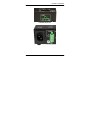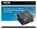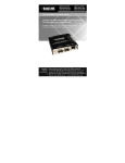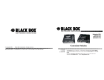
1
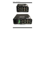
LPH240A-H LPH240A-P PoE Edge Switch Use this economical 6-port 10/100 switch, which has four 802.3af compliant PoE PSE ports for PoE devices. Reduces Network Costs and provides economical solution. Operation is plug-and-play. Radio Interference Regulations Federal Communications Commission and Industry Canada Radio Frequency Interference Statements This equipment generates, uses, and can radiate radio-frequency energy, and if not installed and used properly, that is, in strict accordance with the manufacturer’s instructions, may cause interference to radio communication. It has been tested and found to comply with the limits for a Class A computing device in accordance with the specifications in Subpart B of Part 15 of FCC rules, which are designed to provide reasonable protection against such interference when the equipment is operated in a commercial environment. Operation of this equipment in a residential area is likely to cause interference, in which case the user at his own expense will be required to take whatever measures may be necessary to correct the interference. Changes or modifications not expressly approved by the party responsible for compliance could void the user’s authority to operate the equipment. This digital apparatus does not exceed the Class A limits for radio noise emission from digital apparatus set out in the Radio Interference Regulation of Industry Canada. Le présent appareil numérique n’émet pas de bruits radioélectriques dépassant les limites applicables aux appareils numériques de la classe A prescrites dans le Règlement sur le brouillage radioélectrique publié par Industrie Canada. 724-746-5500 | blackbox.com Page 3 NOM Statement Instrucciones de Seguridad (Normas Oficiales Mexicanas Electrical Safety Statement) 1. Todas las instrucciones de seguridad y operación deberán ser leídas antes de que el aparato eléctrico sea operado. 2. Las instrucciones de seguridad y operación deberán ser guardadas para referencia futura. 3. Todas las advertencias en el aparato eléctrico y en sus instrucciones de operación deben ser respetadas. 4. Todas las instrucciones de operación y uso deben ser seguidas. 5. El aparato eléctrico no deberá ser usado cerca del agua—por ejemplo, cerca de la tina de baño, lavabo, sótano mojado o cerca de una alberca, etc.. 6. El aparato eléctrico debe ser usado únicamente con carritos o pedestales que sean recomendados por el fabricante. 7. El aparato eléctrico debe ser montado a la pared o al techo sólo como sea recomendado por el fabricante. 8. Servicio—El usuario no debe intentar dar servicio al equipo eléctrico más allá a lo descrito en las instrucciones de operación. Todo otro servicio deberá ser referido a personal de servicio calificado. 9. El aparato eléctrico debe ser situado de tal manera que su posición no interfiera su uso. La colocación del aparato electric sobre una cama, sofá, alfombra o superficie similar puede bloquea la ventilación, no se debe colocar en libreros o gabinetes que impidan el flujo de aire por los orificios de ventilación. 10. El equipo eléctrico deber ser situado fuera del alcance de fuentes de calor como radiadores, registros de calor, estufas u otros aparatos (incluyendo amplificadores) que producen calor. Page 4 724-746-5500 | blackbox.com NOM Statement 11. El aparato eléctrico deberá ser connectado a una fuente de poder sólo del tipo descrito en el instructivo de operación, o como se indique en el aparato. 12. Precaución debe ser tomada de tal manera que la tierra fisica y la polarización del equipo no sea eliminada. 13. Los cables de la fuente de poder deben ser guiados de tal manera que no sean pisados ni pellizcados por objetos colocados sobre o contra ellos, poniendo particular atención a los contactos y receptáculos donde salen del aparato. 14. El equipo eléctrico debe ser limpiado únicamente de acuerdo a las recomendaciones del fabricante. 15. En caso de existir, una antena externa deberá ser localizada lejos de las lineas de energia. 16. El cable de corriente deberá ser desconectado del cuando el equipo no sea usado por un largo periodo de tiempo. 17. Cuidado debe ser tomado de tal manera que objectos liquidos no sean derramados sobre la cubierta u orificios de ventilación. 18. Servicio por personal calificado deberá ser provisto cuando: A: El cable de poder o el contacto ha sido dañado; u B: Objectos han caído o líquido ha sido derramado dentro del aparato; o C: El aparato ha sido expuesto a la lluvia; o D: El aparato parece no operar normalmente o muestra un cambio en su desempeño; o E: El aparato ha sido tirado o su cubierta ha sido dañada. 724-746-5500 | blackbox.com Page 5 Trademarks Used in this Manual Trademarks Used in this Manual Black Box and the Double Diamond logo are registered trademarks of BB Technologies, Inc. Ethernet is a trademark of Xerox Corporation NEBS is a trademark of Telcordia Technologies UL is a registered trademark of Underwriters Laboratories Any other trademarks mentioned in this manual are acknowledged to be the property of the trademark owners. We‘re here to help! If you have any questions about your application or our products, contact Black Box Tech Support at 724-746-5500 or go to blackbox.com and click on “Talk to Black Box.” You’ll be live with one of our technical experts in less than 30 seconds. Page 6 724-746-5500 | blackbox.com Table of Contents Table of Contents 1. SPECIFICATIONS .......................................................................... 9 1.1 Technical Specifications ........................................................ 9 1.2 Ordering Information............................................................ 14 2. INTRODUCTION .......................................................................... 19 2.1 Inspecting the Package and Product ................................... 19 2.2 Product description .............................................................. 20 2.3 Frame Buffering and Latency .............................................. 23 2.4 Features and Benefits ......................................................... 26 3. INSTALLATION ............................................................................ 29 3.1 Locating the Edge Switch Unit............................................. 29 3.2 LE1505-RACK for Rack Mounting of LPH240A .................. 32 3.3 LH1505P-RACK for Rack Mounting .................................... 33 3.4 DIN-Rail mounting option .................................................... 34 3.5 Power Requirement for LPH240A (48V) Edge Switch ........ 35 3.6 Powering the LPH240A with –48VDC power input.............. 36 3.7 LPH240A Series, DC-powered, -48VDC Installation ........... 37 3.8 Connecting Ethernet Media ................................................. 38 3.8.1 Connecting Twisted Pair ............................................ 39 3.8.2 Connecting Fiber Optic ST-type, “twist-lock” ............. 40 3.8.3 Connecting Fiber Optic SC-type, "Snap-In" ............... 41 3.8.4 Connecting Single-Mode Fiber Optic ......................... 41 3.8.5 Power Budget Calculations, Fiber Media .................. 42 3.8.6 Connections to NICs .................................................. 43 4. OPERATION ................................................................................ 44 4.1 Dual-Speed Functionality, and Switching ............................ 44 4.2 Auto-cross (MDIX), Auto-negotiation and Speed-sensing ... 46 4.3 Dual LEDs, Front-panel and side-panel .............................. 47 4.4 Hardware operated Alarm Contact ...................................... 48 724-746-5500 | blackbox.com Page 7 Table of Contents 5. TROUBLESHOOTING ................................................................. 50 5.1 Before Calling for Assistance .............................................. 51 5.2 When Calling for Assistance................................................ 52 5.3 Return Material Authorization (RMA) Procedure ................. 53 5.4 Shipping and Packaging Information ................................... 54 APPENDIX A: WARRANTY INFORMATION ......................................... 55 Page 8 724-746-5500 | blackbox.com Chapter 1: Specifications 1. SPECIFICATIONS 1.1 Technical Specifications Ports Performance When a port is operating at 100Mbps: Data Rate: 100Mbps When a port is operating at 10 Mbps: Data Rate: 10 Mbps Network Standards 100Mb: Ethernet IEEE 802.3u, 100BASE-TX, 100BASE-FX 10 Mb: Ethernet IEEE 802.3, 10BASE-T PoE: IEEE 802.3af Auto-sensing for speed: IEEE 802.3u Packet-Processing Between Domains Filter and Forward Rate from 100Mbps ports: 148,800 pps max Filtering and Forwarding Rate from 10 Mbps ports: 14,880 pps max. Processing type: Store and Forward, non-blocking Auto-learning: 2K address table Address buffer age-out time: 300 sec. Packet buffers memory: 128KB, dynamically shared on all domains Latency (not including packet time): 100 to 10 Mbps: 5μs 10 to 100Mbps: 15μs Path Delay Value: 50 BT on all ports LLL(Link-Loss-Learn): Factory default is activated on port 1 and 2 (allow to flush the internal address buffer, and qualify to use with SRing and RSTP for faster recovery in ring topology) 724-746-5500 | blackbox.com Page 9 Chapter 1: Specifications Maximum Ethernet Segment (or Domain) Lengths 10BASE-T (Unshielded twisted pair) - 100 m (328 ft) 100BASE-TX (CAT 5 UTP) - 100 m (328 ft) 100BASE-FX, half-duplex: (multi-mode) - 412 m (1350 ft) 100BASE-FX, full-duplex: (multi-mode) - 2 km (6562 ft) 100BASE-FX, half-duplex: (single-mode) - 412 m (1350 ft) 100BASE-FX, full-duplex: (single-mode) - 20 km (65,620 ft) Operating Environment LPH240A-H: -13ºF to 140ºF (-25ºC to 60ºC) Long term per agency tests (UL) -40ºF to 185ºF (-40ºC to 85ºC) Short term per IEC Type tests. LPH240A-P: -40ºF to 167ºF (-40ºC to 75ºC) Long term per agency tests (UL). -58ºF to 212ºF (-50ºC to 100ºC) Short term per IEC Type tests. Storage Temperature, All models: -40ºF to 185ºF (-40ºC to 85ºC) Cold Start: LPH240A-H to -20ºC LPH240A-P to -40ºC Ambient Relative Humidity: 5% to 95% (non-condensing) Page 10 724-746-5500 | blackbox.com Chapter 1: Specifications Altitude (All models): -200 to 5000ft. (-60 – 15,000 m) Conformal Coating (optional) for humidity protection Note: H and P models are designed for NEBS compliance, including vibration, shock and altitude. Packaging: Enclosure: Rugged sheet metal (Steel). Dimensions of the Switch unit: 3.7 in H x 3.0 in W x 1.7 in D (9.4 cm x 7.6 cm x 4.3 cm) Weight: all models: 9.5 oz. (285g); Cooling Method: Convection on the office model. The Hardened (H) factory floor and Extreme (P) temperature uncontrolled location models have closed cases to withstand dirt and use special thermal techniques to transfer heat to the outside of the case for cooling. ALARM RELAY Terminal Block, H and P models only, two screw terminals: Internal 60VA relay contact: Open for power Off, closed for power On (Hardware). Mean Time Between Failure (MTBF): over 15 years, Telcordia (Bellcore) Method 724-746-5500 | blackbox.com Page 11 Chapter 1: Specifications Direct DC POWER SUPPLY: built-in terminal block for +, -, ground -48V DC internal (range 46 to 60V DC),+ , -, ground. Total power input required: for PoE ports, 66 Watts max. OR 1.4A @48VDC Power Consumption: Typical 3.5 watts, 4 watts max. (All six copper ports) Power Consumption: Typical 7 watts, 8.5 watts max. (4 PoE+ 2 non-PoE fiber port) AC POWER SUPPLY ( using an external power adapter): LPH240A-X-XX-48 models have an (8-15)VDC, 2.5-mm center +ve jack. Option for 12VDC jack for wall mount, only be used to power the LPH240A unit, when no PoE devices are attached, act as non-PoE switch. AC POWER SUPPLY (using internal IEC320 connection) LPH240A-X-XX models have an standard worldwide AC (100-250 VAC) power input via IEC320, male recessed, UL listed and surge protected connector. Port Connectors: RJ-45 Ports: supports 100BASE-TX and 10BASE-T with auto-cross (MDIX). They are shielded 8-pin female connectors for shielded (STP) and unshielded (UTP) Cat 3, 4, 5 cable. Fiber optic port: supports 100Base-FX with a choice of multimode SC, ST or singlemode SC connectors. (By default factory settings is at “Full” duplex on fiber ports). Page 12 724-746-5500 | blackbox.com Chapter 1: Specifications LED Indicators (Front) POWER: 10/100: LK/ACT: F/H: Steady ON when power applied Steady ON for 100Mbps; OFF for 10 Mbps (copper ports only) Steady ON for LINK (LK) with no traffic, BLINKING indicates port is transmitting / receiving (ACT). Steady ON for full-duplex, OFF for half-duplex (Fiber port only) Mounting options Metal mounting clips for panel mounting: included DIN-Rail mounting option: Model # DIN-RAIL MC2 (see Section 3.4) Agency Approvals and Standards Compliance: UL Listed (UL 60950), cUL, CE, Emissions meets FCC Part 15 Class A IEC 61850 EMC and Operating Conditions Class C Power Substations IEEE 1613 Env. Standard for Electrical Power Substations NEBS L3 and ETSI compliant including vibration, shock and altitude NEMA TS-2 and TEES for traffic control equipment Warranty: Three years, return to factory Made in USA 724-746-5500 | blackbox.com Page 13 Chapter 1: Specifications 1.2 Ordering Information MODEL DESCRIPTION LPH240A-H-48 6 port Hardened-rated PoE (802.3af) Power sourcing Edge switch, four RJ-45 (PoE) + two RJ-45 port (non-PoE), 48VDC terminal block for power input. LPH240A-H-SC-48 6 port Hardened-rated PoE (802.3af) Power sourcing Edge switch, four RJ-45 (PoE) + one Multimode SC port (non-PoE), one RJ45 (nonPoE), 48VDC terminal block for power input. LPH240A-H-SSC-48 Same as above, except a Singlemode SC replaces the Multimode SC port. LPH240A-H-ST-48 Same as above, except a Multimode ST replaces the SC port LPH240A-H-2SC-48 6 port Hardened-rated PoE (802.3af) Power sourcing Edge switch, four RJ-45 (PoE) + two Multimode SC port (non-PoE), 48VDC terminal block for power input. LPH240A-H-2SSC-48 Same as above, except a Singlemode SC replaces the Multimode SC port. LPH240A-H-2ST-48 Same as above, except a Multimode ST replaces the SC port. Page 14 724-746-5500 | blackbox.com Chapter 1: Specifications Ordering Information con’t MODEL DESCRIPTION LPH240A-P-48 6 port Extreme-rated PoE (802.3af) Power sourcing Edge switch, four RJ-45 (PoE) + two RJ-45 ports (non-PoE), 48VDC terminal block for power input. LPH240A-P-SC-48 6 port Extreme-rated PoE (802.3af) Power sourcing Edge switch, four RJ-45 (PoE) + one Multimode SC port (non-PoE), one RJ-45 (nonPoE), 48VDC terminal block for power input. LPH240A-P-SSC-48 Same as above, except a Single-mode SC replaces the Multimode SC port. LPH240A-P-ST-48 Same as above, except a Multimode ST replaces the SC port LPH240A-P-2SC-48 6 port Extreme-rated PoE (802.3af) Power sourcing Edge switch, four RJ-45 (PoE) + two Multimode SC port (non-PoE), 48VDC terminal block for power input. LPH240A-P-2SSC-48 Same as above, except a Single-mode SC replaces the Multimode SC port. LPH240A-P-2ST-48 Same as above, except a Multimode ST replaces the SC port. 724-746-5500 | blackbox.com Page 15 Chapter 1: Specifications Ordering Information con’t MODEL DESCRIPTION LPH240A-H 6 port Hardened-rated PoE (802.3af) Power sourcing Edge switch, four RJ-45 (PoE) + two RJ-45 ports (non-PoE), AC IEC320 connector for power input. 6 port Hardened-rated PoE (802.3af) Power sourcing Edge switch, four RJ-45 (PoE) + one Multimode SC port (non-PoE), one RJ45 (nonPoE), AC IEC320 connector for power input. Same as above, except a Single-mode SC replaces the Multimode SC port. Same as above, except a Multimode ST replaces the SC port 6 port Hardened-rated PoE (802.3af) Power sourcing Edge switch, four RJ-45 (PoE) + two Multimode SC port (non-PoE), AC IEC320 connector for power input. Same as above, except a Single-mode SC replaces the Multimode SC port. Same as above, except a Multimode ST replaces the SC port. LPH240A-H-SC LPH240A-H-SSC LPH240A-H-ST LPH240A-H-2SC LPH240A-H-2SSC LPH240A-H-2ST Page 16 724-746-5500 | blackbox.com Chapter 1: Specifications Ordering Information con’t MODEL DESCRIPTION LPH240A-P 6 port Extreme-rated PoE (802.3af) Power sourcing Edge switch, four RJ-45 (PoE) + two RJ45 port (non-PoE), AC IEC320 connector for power input. 6 port Extreme-rated PoE (802.3af) Power sourcing Edge switch, four RJ-45 (PoE) + one Multimode SC port (non-PoE), one RJ45 (nonPoE), AC IEC320 connector for power input. Same as above, except a Singlemode SC replaces the Multimode SC port. Same as above, except a Multimode ST replaces the SC port. 6 port Extreme-rated PoE (802.3af) Power sourcing Edge switch, four RJ-45 (PoE) + two Multimode SC port (non-PoE), AC IEC320 connector for power input. Same as above, except a Singlemode SC replaces the Multimode SC port. Same as above, except a Multimode ST replaces the SC port. LPH240A-P-SC LPH240A-P-SSC LPH240A-P-ST LPH240A-P-2SC LPH240A-P-2SSC LPH240A-P-2ST 724-746-5500 | blackbox.com Page 17 Chapter 1: Specifications LPH240A-H-48 (shown) LPH240A-H (shown) Page 18 724-746-5500 | blackbox.com Chapter 2: Introduction 2. INTRODUCTION 2.1 Inspecting the Package and Product Examine the shipping container for obvious damage prior to installing this product; notify the carrier of any damage that you believe occurred during shipment or delivery. Inspect the contents of this package for any signs of damage and ensure that the items listed below are included. This package should contain: 1 LPH240A, PoE Edge Switch 1 Set of metal clips and screws for secure shelf or wall-mounting 1 Installation and User Guide Remove the Hardened Industrial Switch from the shipping container. Be sure to keep the shipping container in case you need to ship the unit at a later date. If items are missing or damaged, contact Black Box Technical Support at 724-746-5500 or [email protected]. If you need to return the unit, use the original shipping container. Refer to Chapter 5, Troubleshooting, for specific return procedures. 724-746-5500 | blackbox.com Page 19 Chapter 2: Introduction 2.2 Product description LPH240A Industrial PoE switch is a reliable and premium-rated Industrial Ethernet product Switch. Strictly designed to be IEEE 802.3af compatible, the 4-port PoE Edge switch, not only provides PoE options on port #3, 4, 5 and 6 but is also equipped with a LLL (Link-Loss-Learn) feature on port #1 and 2 for use in self-healing redundant LAN structures. Enclosed in a rugged enclosure, designed and developed with premiumgrade extended temperature components, Industrial-rated LPH240A PoE Edge switches are suitable for use in sheltered outdoor locations and temperature-uncontrolled environments with a temperature rating of -40°C to 75°C. The LPH240A PoE Power source Edge Switch combines standard 802.3af Power over Ethernet (PoE) with a small heavy duty 4port PoE ports and 2 100Mb Fiber or 10/100 RJ-45 ports, as per the user requirement. Using an external -48vdc power source, all four of the LPH240A’s Ethernet ports can provide Power as well as 10/100 Mb data transmission over the interconnecting Ethernet cables. So a single Ethernet twisted pair (RJ-45) cable will be able to transmit voice, data, and power from the attached devices. The LPH240A Edge switches are Power Sourcing Equipment (PSE), and are fully compatible with Powered Devices (PD) (e.g wireless access points, IP phones) that comply with the IEEE 802.3af PoE standard. NOTE: Only PoE powered devices complying with IEEE 802.3af are recommended to work successfully with LPH240A power source PoE switches. NON-802.3af compliant PD devices might have COMPATIBILITY issues, and are not being supported with LPH240A PoE switches. Page 20 724-746-5500 | blackbox.com Chapter 2: Introduction The LPH240A switch ports follow an auto-sensing algorithm, so that they provide power only to 802.3af, PoE end devices. PoE is managed by a multi-stage handshake to protect equipment from damage and to manage power budgets. The LPH240A ports will discontinue supplying power when the PoE powered devices are disconnected (on incorrect impedance value). LPH240A units support the 802.3af PoE PSE standard for over-current protection, under-current detection, and fault protection. The LPH240A is an 802.3af standards-compliant way to power and connect a few small Ethernet devices at the edge of a network where AC power is not cost-effective to deploy. Since PoE is rapidly emerging as an Ethernet option in industrial, commercial, outdoor, and military applications, the LPH240A is enabling the efficient deployment of reliable security cameras, VoIP and wireless access networking devices to increase the efficiency of heavy-duty industrial communications. Furthermore, using PoE switches like the LPH240A can produce significant cost savings as well as flexibility and reliability over traditional AC-powered devices. The simplicity of PoE increases reliability and reduces the overall cost of installation and operation. 724-746-5500 | blackbox.com Page 21 Chapter 2: Introduction These are applications where the LPH240A can be used to provide the power and data for these PoE Powered Devices, which require 12-13 watts maximum. - Wireless LAN access points and WLAN Mobility system - VOIP phones - Remote Security Camera - SNTP Clock - Factory floor and building control monitoring (Temperature, Smoke, Heat and other environmental sensors). - Fire alarms - Security devices, like retinal scanners or fingerprint readers - Lighting control - Home automation systems The sleek and compact LPH240A, featured with special thermal techniques for harsh temperatures and a hardened, rugged enclosure provides a multi-purpose choice for all PoE device applications. The LPH240A is a very important source to meet all IEEE 802.3af compliant PoE requirements with multi-choice options. Page 22 724-746-5500 | blackbox.com Chapter 2: Introduction The LPH240A(PoE) Switch provides edge access Ethernet ports in a convenient and compact package. For fiber connectivity of additional non-PoE ports, simply use port#1 and 2 (two RJ-45 or 100 Mb fiber ports with LLL feature) to meet the Fiber and copper 10 or 100 Mb requirements. All LPH240A Power Source Edge Switch models come with two (2) sets of LED indicators. One set is mounted in the end adjacent to three of the RJ-45 ports for easy viewing when the unit is mounted in a rack mount tray. The LPH240A Power Source Switch requires a heavy-duty power supply of -48VDC 1.4Amps (66 watts total consumption) to provide 13-15w power on each port to the PoE unit. Also available with standard AC input utilizing a IEC 320 male recessed connector with internal AC/DC power supply. 2.3 Frame Buffering and Latency The LPH240A-Series PoE Edge Switches are store-andforward switches. Each frame (or packet) is loaded into the Switch’s memory and inspected before forwarding can occur. This technique ensures that all forwarded frames are of a valid length and have the correct CRC, i.e. they are good packets. This eliminates propagation of bad packets, enabling all of the available bandwidth to be used for valid information. While other switching technologies such as "cut-through" or "express" impose minimal frame latency, they will also permit bad frames to propagate to the Ethernet network. The "cut-through" technique permits collision fragment frames, which are a result of late collisions, to be forwarded--which add to the network traffic. 724-746-5500 | blackbox.com Page 23 Chapter 2: Introduction There is no way to filter frames with a bad CRC (the entire frame must be present in order for CRC to be calculated). Since collisions and bad packets are more likely when traffic is heavy, store-and-forward switch technology enables more bandwidth to be available for good packets when the traffic load is greatest. To minimize the possibility of dropping frames on congested ports, each LPH240A Series Edge Switch dynamically allocates buffer space from a 128KB memory pool, ensuring that heavily used ports receive very large buffer space for packet storage. (Many other switches have their packet buffer storage space divided evenly across all ports, resulting in a small, fixed number of packets to be stored per port. When the port buffer fills up, dropped packets result.) This dynamic buffer allocation provides the capability for the maximum resources of the LPH240A Series unit to be applied to all traffic loads, even when the traffic activity is unbalanced across the ports. Since the traffic on an operating network is constantly varying in packet density per port and in aggregate density, the LPH240A Series Edge Switches are constantly adapting internally to provide maximum network performance with the least dropped packets. When the Switch detects that its free buffer queue space is low, the Switch sends industry standard (full-duplex only) PAUSE packets out to the devices sending packets to cause “flow control.” This tells the sending devices to temporarily stop sending traffic, which allows a traffic catch-up to occur without dropping packets. Then, normal packet buffering and processing resumes. This flow-control sequence occurs in a small fraction of a second and is transparent to an observer. Page 24 724-746-5500 | blackbox.com Chapter 2: Introduction Another feature implemented in LPH240A Series Edge Switches is a collision-based flow-control mechanism (when operating at half-duplex only). When the Switch detects that its free buffer queue space is low, the Switch prevents more frames from entering by forcing a collision signal on all receiving half-duplex ports in order to stop incoming traffic. The latency (the time the frame spends in the Switch before it is sent along or forwarded to its destination) of the LPH240A Series PoE Edge Switches varies with the port-speed types. The length of the frame is a variable as it is with all store-and-forward switches. For 10 Mb-to-10 Mb, 10 Mb-to-100Mb or 100Mb-to-10 Mb forwarding, the latency is 15 microseconds plus the packet time of 10 Mb. For 100Mb-to-100Mb forwarding, the latency is 5 microseconds plus the packet time of 100Mb. 724-746-5500 | blackbox.com Page 25 Chapter 2: Introduction 2.4 Features and Benefits Full 100Mb or 10 Mb switching services for high performance Ethernet LPH240A Series PoE Switches provide Fast Ethernet switching on all ports. They perform high speed filter/forward operations on the traffic, giving each port’s segment a full 100Mb (or 10 Mb) of bandwidth. Economical 4-port 10/100 Power Source Switch for PoE devices The compact and robust LPH240A(PoE) acts as a Power plug for all the PoE devices, e.g CCTV camera, VOIP phone, digital clock, and wireless point through its RJ-45 ports and provides a convenient cost-effective power source. The two fiber or copper ports 1 & 2 is featured with LLL (Link-Loss-Learn) and helps in faster recovery for redundant application. Reduces Network Costs and provides economical solution LPH240A Series PoE Switches offer the ideal solution to efficiently and inexpensively connect a Twisted Pair and fiber network with 10Mb or 100Mb and help to expand the Ethernet network in a very convenient and economical way. Choice of one or two100Mb Fiber option, more efficient Designed as a multi-purpose media Edge Switch, the 100Mb fiber port allows the user to convert the media from copper to fiber and the other RJ-45 port can be used as a diagnostic port for more connectivity. Page 26 724-746-5500 | blackbox.com Chapter 2: Introduction Installation is “Plug and Play”, operation is transparent to software The LPH240A Series PoE Switches operate as hardware switches, only forwarding those packets from each domain that are needed on the other domains. Internal address tables are self-learning, enabling users to change port connections or 10/100 domains without affecting operations. Two sets of LEDs for viewing status from any angle. Each LPH240A Series PoE Edge Switch is equipped with two sets (front and side) of LEDs to provide status information when viewed at almost any angle or mounting arrangement whether panel or DinRail mounted. Rugged metal case, Industrial grade LPH240A Series have a robust design and are packaged in a rugged sheet metal enclosure to ensure high reliability and durability even when placed in industrial or outdoor applications. Qualified to use for temperature un-controlled “outdoor” application The LPH240A Extreme rated versions of Edge Switches have an ambient temperature rating between –40ºC to +75ºC for DC models and qualify for temperature uncontrolled “outdoor” applications. Efficient Compact design, for all purpose convenient mounting Featuring a compact steel case with an internal AC and internal DC power supply, LPH240A Series of Edge Switches can be installed in small spaces in cabinets, on table tops, in racks, walls, or DIN-Rail mounted. 724-746-5500 | blackbox.com Page 27 Chapter 2: Introduction MDIX ports to eliminate cross-over cables while cascading All the LPH240A Series Switches are featured with MDI-X (autocross), which easily allows cascading with other Switches, Hubs or media Edges without using the cross-over cable. DC-Power input for PoE Power Source Switch The 802.3af PoE standard power source switch requires 1.4 Amp48VDC to provide enough power for 13-15watts on each RJ-45 port. The Terminal block for -48V DC input is a range of 46V to 60V DC. Hardware operated Alarm terminal block The Alarm contact option on LPH240A enables monitoring for internal power failure, and provides extra reliability to the hardened Switch Link-Loss-Learn feature for faster recovery in redundant network The LLL feature qualifies the Edge switches to actively work along with Managed redundant network structure as a client switch and allow a faster recovery during ring break. The redundant topology must have one managed switch with STP/RSTP feature to control the ring. Page 28 724-746-5500 | blackbox.com Chapter 3: Installation 3. INSTALLATION This section describes the installation of the LPH240A Series PoE Edge Switches, including location, mountings, power supply options and media connections. 3.1 Locating the Edge Switch Unit All the LPH240A Series Switches operate in transparent halfand full-duplex mode. The store and forward switches easily take care of network traffic and can be used as a useful, economical tool to expand an existing network. The compact and lightweight design of the LPH240A Series allows it to be easily installed in almost any location. A Velcro strip may be used for mounting the unit on a vertical surface such as a wall or cabinet, or for securing the unit on a table-top or shelf. Alternatively, metal mounting clips and screws are included for a rugged and secure mounting in any orientation. Installation of the LPH240A Series PoE Edge Switch is a simple procedure. The installation location is dependent upon the physical layout of the Ethernet network and associated cabling. Make sure the unit is installed in a location that is easily accessible to an AC power outlet or the appropriate DC source and where cooling is not inhibited. The green Power (PWR) LED must turn ON when power is applied. 724-746-5500 | blackbox.com Page 29 Chapter 3: Installation Fig. 3.1a LPH240A-x-48VDC (48V model) Page 30 724-746-5500 | blackbox.com Chapter 3: Installation Fig. 3.1b LPH240A-x (AC model) 724-746-5500 | blackbox.com Page 31 Chapter 3: Installation 3.2 LE1505-RACK for Rack Mounting of LPH240A (48V models only) For 19” rack-mounting of LPH240A Series Switches, a rackmount tray is available, the LE1505-RACK. The Switches are mounted with the DC power jack in the back, with the fiber and the RJ-45 connectors in the front. (The mounting spaces of the LE1505-RACK are specific to the LPH240A products and will not permit other models to be properly mounted). In a typical installation, the LE1505-RACK, 19” rack-mount tray will hold a few (three to eight) LPH240A Series Switches, with their power supplies plugged into power strips (not included) in the rear area of the tray. Metal mounting screws in the bottom-front hold the Switches firmly in place. The beveled-top edge of the units permits the LEDs of each unit to be viewed for operational status, even when the units are very close together. Page 32 724-746-5500 | blackbox.com Chapter 3: Installation 3.3 LH1505P-RACK for Rack Mounting (48V models only) The LH1505P-RACK is another option for rack mounting the LPH240A Switches together in a 19” rack-mount tray. These models come with a built-in common universal AC power supply rated at 55 watts at 50°C ambient, 9 VDC regulated output, and supporting up to 10 Switches for LH1505P-RACK. The side-view above is an example of an installation of the model LH1505P-RACK, 19” rack-mount tray, holding a few Switches, each with their power input plugged into the built-in common AC power supply in the rear area of the tray. (PS units that come with the MC’s are not used). Metal mounting screws in the bottom-front hold each of the media converters securing them in the tray and enabling separate removal for service. The dual LEDs permit viewing of Switch status from any angle. 724-746-5500 | blackbox.com Page 33 Chapter 3: Installation 3.4 DIN-Rail mounting option The LPH240A Switches, designed for use in “Factory Floor” Industrial Ethernet environments, are also available for DIN-Rail mounting in an enclosure having DIN Rails. The metal DIN-Rail mounting hardware is optional and needs to be ordered as a separate item. DIN Rail bracket pn: DIN-RAIL MC2 LPH240A-H-48V LPH240A-H Page 34 724-746-5500 | blackbox.com Chapter 3: Installation 3.5 Power Requirement for LPH240A (48V) Edge Switch POWER INPUT: Total Power Consumption: 66 watts max. (1.5A @48VDC) (4PoE+2 non-PoE) copper Total Power Consumption: 66 watts max. (1.6A@48VDC) (4PoE copper+2 non-PoE fiber) Terminal block for -48v DC input (range of 46 to 60V dc), built in for +, - , ground. Note: The 8-15V DC option is also present, but can only be used to power the LPH240A unit when no PoE devices are attached. The device will not function as PoE Switch while powered up via 12VDC power, but as a normal non-PoE Switch. POWER OUTPUT: PoE available on all four RJ-45 ports via Ethernet twisted pair cabling on port pins using the data pair 1,2(-), 3,6(+) PoE 802.3af Power Consumption: 66 watts max. (15.4W max/port) PoE Ports Output voltage: 46 to 57 VDC Over Current Protection, per port: resettable fuse Power Consumption: Typical 3.5 watts, 4 watts max. (All six copper ports) Power Consumption: Typical 7 watts, 8.5 watts max. (4 PoE+ 2 non-PoE fiber port) 724-746-5500 | blackbox.com Page 35 Chapter 3: Installation 3.6 Powering the LPH240A with –48VDC power input Each LPH240A Switch is equipped with an internal DC power supply, and has built-in screw terminals for secure attachment of the power input leads. The three DC power input terminal block choices are for use with -48VDC power. Where an AC power adaptor is used, DC is supplied via the jack. Power input from the DC terminal block and the jack may be connected simultaneously for power input redundancy. Page 36 724-746-5500 | blackbox.com Chapter 3: Installation 3.7 LPH240A Series, DC-powered, -48VDC Installation This section describes the proper connection of the -48VDC leads to the DC power terminal block on the LPH240A PoE Edge Switch. The DC terminal block on the LPH240A is located on the left side of the unit and is equipped with three (3) screw-down lead posts. The power terminals are identified as positive (+) and negative (-), and they are floating inside the unit so that either of the terminals may be grounded by the user if desired. The chassis is “earth” or ground (GND). The connection procedure is straightforward. Simply insert the DC leads to the LPH240A power terminals, positive (+) and negative (-) screws. The use of Ground (GND) optional; it connects to the LPH240A chassis. Ensure that each lead is securely tightened from the top, as shown on above picture with arrow. NOTE: Always use a voltmeter to measure the voltage of the incoming power supply and figure out the +ve potential lead or -ve potential lead. The more +ve potential lead will connect to the post labeled “+ve” and the rest to the “-ve”. The GND can be hooked up at the last. When power is applied, the green PWR LED will illuminate. 724-746-5500 | blackbox.com Page 37 Chapter 3: Installation 3.8 Connecting Ethernet Media The LPH240A-Series PoE Edge Switches can be connected to two media types i.e. fiber and copper (RJ-45) types, run at 100BASE-TX, 10BASE-T and 100BASE-FX only. CAT 5 cables should be used when making 100BASE-TX connections. When the ports are used as 10BASET ports, CAT 3 may be used. In either case, the maximum distance for unshielded twisted pair cabling is 100 meters (328 ft). For fiber port 10BASE-FL or 100BASE-FX multi-mode, 50/125 or 62.5/125 microns cabling can be used, whereas for single-mode, 9/125 microns cabling should be used. Fiber cabling supports much longer cable distance and higher bandwidths as compared to copper wiring. Media IEEE Standard Connector Twisted Pair (CAT 3 or 5) 10BASE-T RJ-45 Twisted Pair (CAT 5) 100BASE-TX RJ-45 Fiber (Multi-mode) 100BASE-FX ST, SC Fiber (Single-mode) 100BASE-FX SC NOTE : It is recommended that high quality CAT. 5 cables (which work for both 10 Mbps and 100Mbps) be used whenever possible in order to provide flexibility in a mixed-speed network, since LPH240A-series switch ports are auto-sensing for either 10 and 100Mbps. Note that the auto-cross function does not operate, if the port is fixed or not supporting auto-negotiation. Page 38 724-746-5500 | blackbox.com Chapter 3: Installation 3.8.1 Connecting Twisted Pair (RJ-45, CAT 3 or CAT 5, Unshielded or Shielded) The following procedure describes how to connect a 10BASE-T or 100BASE-TX twisted pair segment to the RJ-45 port. The procedure is the same for both unshielded and shielded twisted pair cables. 1. 2. 3. 4. Using standard twisted pair media, insert either end of the cable with a RJ-45 plug into the RJ-45 connector of the port. Note that, even though the connector is shielded, either unshielded or shielded cables and wiring may be used. Connect the other end of the cable to the corresponding device. Use the LINK LED to ensure proper connectivity by noting that the LED will be illuminated when the unit is powered and proper connection is established. If this does not help, ensure that the cable is connected properly and that the device on the other end is powered and is not defective. For Port # 1 or 1SW, if the LINK LED is not illuminated, move the switch which has a cross-over or up-link for linking to another hub or Switch. 724-746-5500 | blackbox.com Page 39 Chapter 3: Installation 3.8.2 Connecting Fiber Optic ST-type, “twist-lock” The following procedure applies to installations using ST-type fiber connectors. This procedure applies to ports using multi-mode ST fiber connectors. 1. 2. Before connecting the fiber optic cable, remove the protective dust caps from the tips of the fiber connectors. Save these dust caps for future use. Wipe clean the ends of the dual connectors with a soft cloth or lintfree lens tissue dampened in alcohol. Make certain the connectors are clean before connecting. Note: One strand of the duplex fiber optic cable is coded using color bands at regular intervals; you must use the color-coded strand on the associated ports at each end of the fiber optic segment. 3. Connect the Transmit (TX) port (light colored post) on the Fiber port to the Receive (RX) port of the remote device. Begin with the color-coded strand of the cable for this first TX-to-RX connection. 4. Connect the Receive (RX) port (dark colored post) to the Transmit (TX) port of the remote device. Use the non-color coded fiber strand for this. The LINK LED on the front of the fiber connector will illuminate when a proper connection has been established at both ends (and when power is ON in the unit). If LINK is not lit after cable connection, the normal cause is improper cable polarity. Swap the fiber cables at the fiber connector to remedy this situation. 5. Page 40 724-746-5500 | blackbox.com Chapter 3: Installation 3.8.3 Connecting Fiber Optic SC-type, "Snap-In" The following procedure applies to installations using SCtype fiber connectors, i.e., using multi-mode SC and SC single-mode. While connecting fiber media to SC connectors, simply snap on the two square male connectors into the SC female jacks of the Fiber connector until it clicks and secures. 3.8.4 Connecting Single-Mode Fiber Optic When using single-mode fiber cable, be sure to use singlemode fiber port connectors. Single-mode fiber cable has a smaller diameter than multi-mode fiber cable (9/125 microns for single-mode, 50/125 or 62.5/125 microns for multi-mode where xx/xx are the diameters of the core and the core plus the cladding respectively). Single-mode fiber allows full bandwidth at longer distances, about 20Km with the Single-mode SC. The same procedures as for multi-mode fiber apply to single-mode fiber connectors. Follow the steps listed in Section 3.8.2 above. 724-746-5500 | blackbox.com Page 41 Chapter 3: Installation 3.8.5 Power Budget Calculations, Fiber Media Receiver Sensitivity and Transmitter Power are the parameters necessary to compute the power budget. To calculate the power budget of different fiber media installations using Black Box Heavy Duty Edge Switches, the following equations should be used: OPB (Optical Power Budget) = PT(min) - PR(min) where PT = Transmitter Output Power, and PR = Receiver Sensitivity Worst case OPB = OPB - 1dB(for LED aging) - 1dB(for insertion loss) Worst case distance = {Worst case OPB, in dB} / [Cable Loss, in dB/Km] where the “Cable Loss” for 62.5/125 and 50/125μm (m.m.) is 2.8dB/km, and the “Cable Loss” for 100/140 (Multi-mode) is 3.3 dB/km, and the “Cable Loss” for 9/125 (Single-mode) is 0.5 dB/km * Note: The use of either multi-mode or single-mode fiber to operate at 100Mbps speed over long distances (i.e., over approx. 400 meters) can be achieved only if the following factors are both applied: • The 100Mb fiber segment must operate in full-duplex (FDX) mode, and • The worst-case OPB of the fiber link must be greater than the fiber cable’s passive Attenuation. (Attenuation = Cable loss + LED aging loss + Insertion loss + safety factor) Page 42 724-746-5500 | blackbox.com Chapter 3: Installation 3.8.6 Connections to NICs which support Auto-Negotiation, RJ-45 ports The copper ports of LPH240A Edge Switches will function properly with NICs (Network Interface Cards) which support AutoNegotiation, and the Fast Link Pulse (FLP) coding for the 100BASE-TX signaling system. When connecting a NIC to the LPH240A-Series, it may be necessary to reload the NIC drivers on the user device if the NIC has been communicating with a protocol other than 100BASE-TX (such as 10BASE-T). When 100Mb operation is agreed and in use, the 10/100 LED is illuminated steady ON and OFF if 10 Mbps traffic is in use. 724-746-5500 | blackbox.com Page 43 Chapter 4: Operation 4. OPERATION 4.1 Dual-Speed Functionality, and Switching The LPH240A Series Edge Switches provide SIX switched ports with combination of fiber and copper or copper only. The architecture supports a dual speed switching environment, with standard auto-negotiation capability. The switched RJ-45 ports are full- or half-duplex auto-sensing for mode and speed, and auto-cross for plug polarity. (See Section 4.2). When the connected device is 10 Mbps, the LPH240A obeys all the rules of 10 Mbps Ethernet configurations. The 10 Mbps users can “communicate” with 100Mbps users as well as other 10 Mbps users through the switch. Similarly, the 100Mbps traffic obeys the rules of 100Mbps Ethernet, and can communicate with 10 Mb and 100Mb users. LPH240A Series units are plug-and-play devices. There is no software configuring to be done at installation or for maintenance, even for the LLL ports. The internal functions of both are described below. Page 44 724-746-5500 | blackbox.com Chapter 4: Operation Switching, Filtering and Forwarding Each time a packet arrives on one of the switched ports, the decision is taken to either filter or to forward the packet. Packets whose source and destination addresses lie on the same port segment will be filtered, constraining them to one port and relieving the rest of the network from processing them. A packet whose destination address is on another port segment will be forwarded to the appropriate port, and will not be sent to the other ports where it is not needed. Packets needed for maintaining the operation of the network (such as occasional multi-cast packets) are forwarded to all ports. The LPH240A Series Edge Switches operate in the store-and-forward switching mode, which eliminates bad packets and enables peak performance to be achieved when there is heavy traffic on the network. Switching, Address Learning The LPH240A Series units have address table capacity of 2K node addresses, and are suitable for use in large networks. They are self-learning, so that as nodes are added or removed or moved from one segment to another, the LPH240A Series switch automatically keeps up with node locations. An address-aging algorithm causes least-used addresses to fall out in favor of new frequently-used addresses. To reset the address buffer, cycle power down-and-up. 724-746-5500 | blackbox.com Page 45 Chapter 4: Operation 4.2 Auto-cross (MDIX), Auto-negotiation and Speed-sensing The RJ-45 ports support auto-cross (MDI or MDI-X) in the auto-negotiation mode according to the IEEE 802.3u standard. No crossover cables are needed on RJ-45 port, when connecting the LPH240A Series to other unmanaged switches, legacy hubs, managed switches, media-converter etc. Please note that there can be conditions with managed switches where the switch manager fixes the port settings via software, and the result of the auto-negotiation is changed in the managed switch by the manager commands. In such cases, the 10/100 speed or the F/H mode may be affected, but autocross in the LPH240A switches will still work. The auto-cross function cannot be disabled. When an RJ-45 cable connection is made, and each time LINK is enabled, auto-negotiation takes place (except for legacy products, which do not have auto-negotiation and which go to the default state accordingly). The LPH240A Switches advertises its capability for 10 or 100 Mbps speed and F/H duplex mode, and the device at the other end of the cable should similarly advertise/respond. Both sides will agree to the speed and mode to be used per the IEEE 802.3u standard. Depending upon the devices connected, this will result in agreement to operate at either 10 Mbps or 100Mbps speed, and full- or half-duplex mode. Page 46 724-746-5500 | blackbox.com Chapter 4: Operation 4.3 Dual LEDs, Front-panel and side-panel LED Description PWR Illuminates GREEN to indicate power applied. LK/ ACT Steady ON for LINK w/no traffic, blinking for activity per port. LINK will turn off in the event connectivity is lost between the ends of the twisted pair segment or a loss of power occurs in the unit or remote device. The Link ports are also represented by LA1, LA2, LA3…LA6. (Steady On or steady Off indicates no Receive Activity). 10/100 Steady ON for 100Mb speed, OFF for 10Mb speed per port (copper ports) F/H (FH1, FH2) Steady ON for Full duplex (F/D) mode, OFF for Half duplex (H/D) mode per port (For fiber port only) NOTE: The port #1 and 2 is being assigned for copper or fiber port for different models. On all copper 10/100 ports model (e.g LPH240A-H-48), the LEDs 10 or 100 denotes for copper port only. For the model 4 copper +2 fiber or 5 copper +1fiber, (e.g LPH240A-H-2SC-48) the F or H denotes for fiber port only. 724-746-5500 | blackbox.com Page 47 Chapter 4: Operation 4.4 Hardware operated Alarm Contact for monitoring internal power supply The two screws Alarm Contact features are standard on LPH240A Series, and provide Normally Closed (NC) contacts to which the user can attach one sets of status monitoring wires at the green terminal block. When this option is present, the terminal block for Alarm Contacts is part of the Power Input panel in the LPH240A case. The DC power input connection is in the same panel. The NC Alarm Contact is held close when there is power on the main board inside of the LPH240A. This provides a “Hardware operated Alarm” because the NC contacts will open when internal power is lost, either from an external power down condition or by the failure of the power supply inside of the LPH240A Switch. Useful info about Alarm Contacts in LPH240A: 1. 2. 3. Two-position terminal block (1,2) provided next to the DC power input, as shown above. The Alarm Relay contact connected to the two terminals (1,2) is hardware operated. By default it is NC (normally closed). It will open if there is any loss of power to the electronics inside of the unit. Page 48 724-746-5500 | blackbox.com Chapter 4: Operation Alarm terminal locations: LPH240A (48V model) LPH240A (AC model) 724-746-5500 | blackbox.com Page 49 Chapter 5: Troubleshooting 5. TROUBLESHOOTING All Black Box Ethernet products are designed to provide reliability and consistently high performance in all network environments. The installation of Black Box LPH240A Switch is a straightforward procedure (see INSTALLATION, Section 3.0); the operation is also straight forward and is discussed in Section 4. Should problems develop during installation or operation, this section is intended to help locate, identify and correct these types of problems. Please follow the suggestions listed below prior to contacting your supplier. However, if you are unsure of the procedures described in this section or if the LPH240A Switch is not performing as expected, do not attempt to repair the unit; instead contact your supplier for assistance or contact Black Box Technical Support at 724-746-5500 or [email protected]. Page 50 724-746-5500 | blackbox.com Chapter 5: Troubleshooting 5.1 Before Calling for Assistance 1. If difficulty is encountered when installing or operating the unit, refer back to the Installation Section of the applicable chapter of this manual. Also check to make sure that the various components of the network are interoperable. 2. Check the cables and connectors to ensure that they have been properly connected and the cables/wires have not been crimped or in some way impaired during installation. (About 90% of network downtime can be attributed to wiring and connector problems.) 3. If the problem is isolated to a network device other than the LPH240A Switch product, it is recommended that the problem device is replaced with a known good device. Verify whether or not the problem is corrected. If not, go to Step 4 below. If the problem is corrected, the LPH240A Switch and its associated cables are functioning properly. 4. If the problem continues after completing Step 3 above, contact your supplier of the LBH08x/LBH18x Industrial Switch unit or if unknown, contact Black Box Tech support (see page 4 of this guide) for assistance. 724-746-5500 | blackbox.com Page 51 Chapter 5: Troubleshooting 5.2 When Calling for Assistance Please be prepared to provide the following information. 1. A complete description of the problem, including the following points: a. The nature and duration of the problem; b. Situations when the problem occurs; c. The components involved in the problem; d. Any particular application that, when used, appears to create the problem; 2. An accurate list of Black Box product model(s) involved, with serial number(s). Include the date(s) that you purchased the products from your supplier. 3. It is useful to include other network equipment models and related hardware, including personal computers, workstations, terminals and printers; plus, the various network media types being used. 4. A record of changes that have been made to your network configuration prior to the occurrence of the problem. Any changes to system administration procedures should all be noted in this record. Page 52 724-746-5500 | blackbox.com Chapter 5: Troubleshooting 5.3 Return Material Authorization (RMA) Procedure All returns for repair must be accompanied by a Return Material Authorization (RMA) number. To obtain an RMA number, please contact Black Box Tech support. Please have the following information readily available: Name and phone number of your contact person. Name of your company / institution Your shipping address Product name Serial Number (or Invoice Number) Packing List Number (or Sales Order Number) Date of installation Failure symptoms, including a full description of the problem. Black Box will carefully test and evaluate all returned products, will repair products that are under warranty at no charge, and will return the warranty-repaired units to the sender with shipping charges prepaid (see Warranty Information, Appendix A, for complete details). However, if the problem or condition causing the return cannot be duplicated by Black Box, the unit will be returned as: No Problem found. Black Box reserves the right to charge for the testing of nondefective units under warranty. Testing and repair of product that is not under warranty will result in a customer (user) charge. 724-746-5500 | blackbox.com Page 53 Chapter 5: Troubleshooting 5.4 Shipping and Packaging Information Should you need to ship the unit back to Black Box, please follow these instructions: 1. Package the unit carefully. It is recommended that you use the original container if available. Units should be wrapped in a "bubble-wrap" plastic sheet or bag for shipping protection. (You may retain all connectors and this Installation Guide.) CAUTION: Do not pack the unit in Styrofoam "popcorn" type packing material. This material may cause electro-static shock damage to the unit. 2. Clearly mark the Return Material Authorization (RMA) number on the outside of the shipping container. 3. Black Box is not responsible for your return shipping charges. 4. Ship the package to: Black Box Network Services (contact Black Box Tech support for information) Page 54 724-746-5500 | blackbox.com Appendix A: Warranty APPENDIX A: WARRANTY INFORMATION Black Box warrants its products to be free from defects in materials and workmanship for a period of three (3) years from the date of shipment. During this warranty period, Black Box will repair or, at its option, replace components in the products that prove to be defective at no charge other than shipping and handling, provided that the product is returned pre-paid to Black Box. This warranty will not be effective if, in the opinion of Black Box, the product has been damaged by misuse, misapplication, or as a result of service or modification other than by Black Box. Black Box reserves the right to make a charge for handling and inspecting any product returned for warranty repair which turns out not to be faulty. 724-746-5500 | blackbox.com Page 55 LPH240A, rev. 1