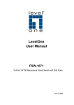
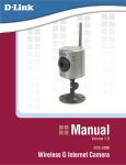
1
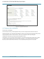
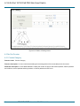
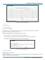
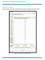
LPB708A
LPB716A
LPB724A
8-/16-/24-Port 10/100 PoE PSE Web Smart Switch
Connect VoIP phones, IP cameras, or any PoE PD
devices through manageable, switched links.
Complies with 802.af Power-over Ethernet standard.
Supports Web-based configuration and management.
Uses Auto-MDI/MDI-X so you can use crossover
or straight-through cables.
Automatically determines port speed.
Housed in a desktop metal case
with an internal power supply.
Includes PoE ON/OFF remote control.
8-/16-/24-Port 10/100 PoE PSE Web Smart Switch
Federal Communications Commission and Industry Canada Radio Frequency Interference
Statements
This equipment generates, uses, and can radiate radio-frequency energy, and if not installed and used properly, that is, in
strict accordance with the manufacturer’s instructions, may cause interference to radio communication. It has been tested
and found to comply with the limits for a Class A computing device in accordance with the specifications in Subpart J of
Part 15 of FCC rules, which are designed to provide reasonable protection against such interference when the equipment
is operated in a commercial environment. Operation of this equipment in a residential area is likely to cause interference,
in which case the user at his own expense will be required to take whatever measures may be necessary to correct the
interference.
Changes or modifications not expressly approved by the party responsible for compliance could void the user’s authority
to operate the equipment.
This digital apparatus does not exceed the Class A limits for radio noise emission from digital apparatus set out in the
Radio Interference Regulation of Industry Canada.
Le présent appareil numérique n’émet pas de bruits radioélectriques dépassant les limites applicables aux appareils
numériques de la classe A prescrites dans le Règlement sur le brouillage radioélectrique publié par Industrie Canada.
2
724-746-5500 l www.blackbox.com
NOM Statement and CE Directive
Normas Oficiales Mexicanas (NOM) Electrical Safety Statement
INSTRUCCIONES DE SEGURIDAD
1.
2.
3.
4.
5.
Todas las instrucciones de seguridad y operación deberán ser leídas antes de que el aparato eléctrico sea operado.
Las instrucciones de seguridad y operación deberán ser guardadas para referencia futura.
Todas las advertencias en el aparato eléctrico y en sus instrucciones de operación deben ser respetadas.
Todas las instrucciones de operación y uso deben ser seguidas.
El aparato eléctrico no deberá ser usado cerca del agua—por ejemplo, cerca de la tina de baño, lavabo, sótano
mojado o cerca de una alberca, etc..
6. El aparato eléctrico debe ser usado únicamente con carritos o pedestales que sean recomendados por el fabricante.
7. El aparato eléctrico debe ser montado a la pared o al techo sólo como sea recomendado por el fabricante.
8. Servicio—El usuario no debe intentar dar servicio al equipo eléctrico más allá a lo descrito en las instrucciones de
operación. Todo otro servicio deberá ser referido a personal de servicio calificado.
9. El aparato eléctrico debe ser situado de tal manera que su posición no interfiera su uso. La colocación del aparato
eléctrico sobre una cama, sofá, alfombra o superficie similar puede bloquea la ventilación, no se debe colocar en
libreros o gabinetes que impidan el flujo de aire por los orificios de ventilación.
10. El equipo eléctrico deber ser situado fuera del alcance de fuentes de calor como radiadores, registros de calor,
estufas u otros aparatos (incluyendo amplificadores) que producen calor.
11. El aparato eléctrico deberá ser connectado a una fuente de poder sólo del tipo descrito en el instructivo de
operación,
o como se indique en el aparato.
12. Precaución debe ser tomada de tal manera que la tierra fisica y la polarización del equipo no sea eliminada.
13. Los cables de la fuente de poder deben ser guiados de tal manera que no sean pisados ni pellizcados por objetos
colocados sobre o contra ellos, poniendo particular atención a los contactos y receptáculos donde salen del aparato.
14. El equipo eléctrico debe ser limpiado únicamente de acuerdo a las recomendaciones del fabricante.
15. En caso de existir, una antena externa deberá ser localizada lejos de las lineas de energia.
16. El cable de corriente deberá ser desconectado del cuando el equipo no sea usado por un largo periodo de tiempo.
17. Cuidado debe ser tomado de tal manera que objectos liquidos no sean derramados sobre la cubierta u orificios de
ventilación.
18. Servicio por personal calificado deberá ser provisto cuando:
A: El cable de poder o el contacto ha sido dañado; u
B: Objectos han caído o líquido ha sido derramado dentro del aparato; o
C: El aparato ha sido expuesto a la lluvia; o
D: El aparato parece no operar normalmente o muestra un cambio en su desempeño; o
E: El aparato ha sido tirado o su cubierta ha sido dañada.
European Community (CE) Electromagnetic Compatibility Directive
This equipment has been tested and found to comply with the protection requirements of European Emission Standard
EN55022/EN61000-3 and the Generic European Immunity Standard EN55024.
EMC:
EN55022 (2003)/CISPR-2 (2002): class A
IEC61000-4-2 (2001): 4KV CD, 8KV AD
IEC61000-4-3 (2002): 3V/m
IEC61000-4-4 (2001):1KV (power line), 0.5KV (signal line)
724-746-5500 l www.blackbox.com 3
8-/16-/24-Port 10/100 PoE PSE Web Smart Switch
Table of Contents
1. Specifications ..................................................................................................................................................................6
1.1
Hardware Specifications ........................................................................................................................................6
1.2
Management Software Specifications ..................................................................................................................7
2. Overview
..................................................................................................................................................................8
2.1
Introduction .............................................................................................................................................................8
2.2
Features ..................................................................................................................................................................8
2.3
What’s Included .....................................................................................................................................................8
2.4
Front and Rear Panels ..........................................................................................................................................9
2.4.1
Front Panel...............................................................................................................................................9
2.4.2
Back Panel ...............................................................................................................................................9
2.5
LED Indicators .....................................................................................................................................................10
3. Installation
................................................................................................................................................................12
3.1
Hardware and Cable Installation ........................................................................................................................12
3.1.1
TP Port and Cable Installation .............................................................................................................12
3.1.2
Installing Optional SFP Transceiver Module ......................................................................................12
3.1.3
Power On ..............................................................................................................................................13
3.2
Installing Switch to 19-inch Wiring Closet Rail ..................................................................................................13
3.3
Cabling Requirement ...........................................................................................................................................13
3.4
Switch Cascading in Topology ............................................................................................................................14
3.5
Typical Network Topology in Deployment ..........................................................................................................14
3.6
Set IP Address, Subnet Mask, and Default Gateway IP Address.....................................................................16
4. Operation of Web-based Management .........................................................................................................................18
4.1
Web Management Home Overview ....................................................................................................................19
4.2
Administrator ........................................................................................................................................................19
4.2.1
Authentication Configuration ................................................................................................................20
4.2.2
System IP Configuration ......................................................................................................................20
4.2.3
System Status .......................................................................................................................................21
4.2.4
Load Default Setting .............................................................................................................................22
4.2.5
Firmware Update ..................................................................................................................................22
4.2.6
Reboot Device ......................................................................................................................................22
4.3
Port Management ................................................................................................................................................22
4.3.1
Port Configuration .................................................................................................................................23
4.3.2
Port Mirroring ........................................................................................................................................23
4.3.3
Bandwidth Control ................................................................................................................................24
4.3.4
Broadcast Storm Control.......................................................................................................................25
4.3.5
PoE ........................................................................................................................................................25
4.4
VLAN Setting .......................................................................................................................................................26
4.4.1
VLAN Mode............................................................................................................................................26
4.4.2
Port-based VLAN—VLAN Member ......................................................................................................26
4.4.3
Tag-based VLAN1 .................................................................................................................................27
4.4.4
Tag-based VLAN—VLAN Member.......................................................................................................28
4.4.5
Multi to 2 Setting ....................................................................................................................................29
4.5
Per Port Counter...................................................................................................................................................30
4.5.1
Counter Category ..................................................................................................................................30
4.6
QoS Setting...........................................................................................................................................................31
4.6.1
Priority Mode ..........................................................................................................................................31
4.6.2
Class of Service ....................................................................................................................................31
4.6.3
Class of Service—TCP/UDP ................................................................................................................32
4.6.4
Class of Service—IP TOS/DS ..............................................................................................................33
4.6.5
Class of Service—802.1p .....................................................................................................................33
4.6.6
Class of Service—Physical Port ...........................................................................................................34
4.7
Security ................................................................................................................................................................34
4.7.1
MAC Address Configuration .................................................................................................................34
4.7.2
TCP/UDP Filter Configuration...............................................................................................................35
4
724-746-5500 l www.blackbox.com
Table of Contents
4.8
Spanning Tree ......................................................................................................................................................36
4.8.1
STP Bridge Setting ................................................................................................................................36
4.8.2
STP Port Setting ....................................................................................................................................37
4.9
Trunking ................................................................................................................................................................38
4.10 Backup/Recovery .................................................................................................................................................40
4.11 Miscellaneous Setting ..........................................................................................................................................40
4.12 Logout ................................................................................................................................................................41
5. Troubleshooting ...............................................................................................................................................................42
6. IP Address Assignment...................................................................................................................................................43
6.1
IP Address.............................................................................................................................................................43
6.2
Subnet Mask .........................................................................................................................................................43
6.3
Default Gateway ...................................................................................................................................................44
6.4
DNS
................................................................................................................................................................45
724-746-5500 l www.blackbox.com 5
8-/16-/24-Port 10/100 PoE PSE Web Smart Switch
1. Specifications
Hardware Specifications
Buffer Memory: LPB708A, LPB716A: Embedded 1625 K bits frame buffer;
LPB724A: 2750 K bits
Certifications: FCC Class A, CE
Flow Control: IEEE802.3x compliant for full duplex;
Backpressure flow control for half duplex
Full Forwarding/Filtering Packet Rate: PPS (packets per second):
Forwarding Rate
148,800 PPS
14,880 PPS
Speed
100 Mbps
10 Mbps
MAC Address and Self-learning: 4K MAC address
Network Interface: 8-port/ 16-port/ 24-port 10/100BaseT(X) with PoE (half/full power);
2-port combo UTP/SFP Gigabit (LPB724A only)
Standards Compliance: IEEE 802.3 10BASE-T, IEEE 802.3u 100BASE-TX, IEEE 802.3x Flow Control, IEEE 802.3ad
Trunk, IEEE 802.3af Power over Ethernet (PoE), IEEE 802.1Q VLAN, IEEE 802.1p QoS,
IEEE 802.1x Port-based Network Access Control, IEEE 802.1d Spanning Tree Protocol,
IEEE 802.1w Rapid Spanning Tree Protocol
Switching Method: Store and forward
Transmission Media: 10BASE-T CAT3, 4, 5 UTP/STP; 100BASE-TX CAT5 UTP/STP
Transmission Mode: 10/100Mbps support full- or half-duplex
Transmission Speed: 10/100 Mbps for TP
Connectors: LPB708A: (8) RJ-45;
LPB716A: (16) RJ-45;
LPB724A: (24) RJ-45, (2) combo UTP/SFP
Indicators: LEDs: Per Port: LINK/ACT;
PoE Port: Act/Status;
Per Unit: Power
Temperature Tolerance: Operating: 32 to 131° F (0 to 55°C);
Storage Temperature: -4 to 194°F (-20 to 90 C)
Humidity Tolerance: 10 to 90% RH (non-condensing)
Power: Input: 100–240V/AC, 50–60Hz;
PoE Power Output: 15.4 Watts (Max) per port
Power Consumption: LPB708A: 130 Watts (maximum); LPB716A: 260 Watts (maximum);
LPB724A: 390 Watts (maximum)
Size: LPB708A: 1.7”H x 6.3”W x 10.5”D (4.4 x 16 x 26.6 cm);
LPB716A, LPB724A: 1.7”H x 8.7”W x 17.3”D (4.4 x 22 x 44 cm)
Weight: LPB708A: 3.5 lb. (1.6 kg); LPB716A: 7.9 lb. (3.6 kg); LPB724A: 8.6 lb. (3.9 kg)
6
724-746-5500 l www.blackbox.com
Chapter 1: Specifications
Management Software Specifications
Backup/Recovery Configuration
IGMP Snooping: V1/V2
Port Management: Port Configuration, Port Mirroring, Bandwidth Control, Broadcast Strom Control, PoE On/ Off Setting
QoS Setting: Up to 4 queues
RSTP/STP: Rapid/Spanning Tree Protocol
VLAN Function: Port-Based/802.1Q-Tagged, up to 256 active VLANs in one switch
VLAN Setting: Port-based/Tag-based, VLAN ID: 1–4094K
Security Filter: MAC address filtering, TCP/UDP filtering
Trunking: 2 groups (1–4 ports for each group)
724-746-5500 l www.blackbox.com 7
8-/16-/24-Port 10/100 PoE PSE Web Smart Switch
2. Overview
2.1 Introduction
LPB708A/LPB716A/LPB724A, is a standard 8-Port/16-Port/24-Port 10/100 PoE PSE Web Smart Switch that meets all
IEEE 802.3u/x Ethernet specifications. The switch includes 8-, 16-, or 24-Port 10/100Mbps TP ports. LPB724A also
features two combo UTP/SFP Gigibit ports. Manage the switch through an Ethernet port using Web-based management.
The switch also features QoS (Quality of Service), Spanning Tree, VLAN, Port Trunking, and IGMP Snooping capability
via the intelligent software. It is suitable for small- and medium-sized office applications.
This PSE switch also complies with IEEE 802.3af. Its advanced autosensing algorithm enables power devices (PD)
discovery, classification, current limit, and other necessary functions. Safety features include short-circuit protection and
power-out auto-detection to PD.
2.2 Features
Power-over-Ethernet: Provides built-in 802.3af Power over Ethernet for network sites that need to run power over the
network cables. Each of the 10/100BASE-TX Ethernet ports on this switch provides up to 15.4 watts power for
connected wireless access points, IP phones and other PoE-supported devices, enabling them to be deployed at
difficult places such as on high walls and ceilings, where AC power outlets are not readily available.
QoS: Supports Quality of Service by the IEEE 802.1P standard. There are four priority queues enabling users to run
bandwidth-sensitive applications such as streaming multimedia and VoIP in network.
Spanning Tree: Supports IEEE 802.1D, IEEE 802.1w (RSTP: Rapid Spanning Tree Protocol) standards to prevent
network loops that could cause a broadcast storm.
VLAN: Supports Port-based VLAN and IEEE802.1Q Tag VLAN. Also supports 256 active VLANs and VLAN ID 1–
4094.
Port Trunking: Supports static port trunking and port trunking with IEEE 802.3ad LACP.
IGMP Snooping: Establishes the multicast groups to forward the multicast packet to the member ports, and avoids
wasting the bandwidth while IP multicast packets are running over the network.
Security: Support MAC Address and TCP/UDP filtering to prevent unknown users or un-authorized actions connected
to network.
2.3 What’s Included
Your package should include the following items. If anything is missing or damaged, contact Black Box Technical Support
at 724-746-5500 or [email protected].
(1) 8-, or 16-, or 24-Port 10/100 PoE PSE Web Smart Switch
(1) Mounting Accessory (for 19” Rackmount)
(1) AC Power Cord
(1) CD-ROM containing this user’s manual in PDF format
8
724-746-5500 l www.blackbox.com
Chapter 2: Overview
2.4 Front and Back Panels
2.4.1 Front Panel
LED Indicators
8 RJ-45 TP ports
LPB708A.
LED Indicators
(16) RJ-45 TP ports
LPB716A.
LED Indicators
24 RJ-45 TP Ports
2 Combo UTP/SFP
Ports
LPB724A.
Figure 2-1. LPB708A, LPB716A, LPB724A Front panels.
2.4.2 Back Panel
AC Power Input
Figure 2-2. Back panel.
724-746-5500 l www.blackbox.com 9
8-/16-/24-Port 10/100 PoE PSE Web Smart Switch
2.5 LED Indicators
LPB708A
LPB716A
LPB724A
Figure 2-3. LED Indicators.
10
724-746-5500 l www.blackbox.com
Chapter 2: Overview
Table 2-1. LED descriptions.
LED
Color
Systems LED (All models)
Power
Green
Reset
Function
Lit when power is on
Used to restore management system
10/100 Ethernet TP Port 1 to 8 LEDs (LPB708A)
LINK/ACT
Green
Blinks when any traffic is present
Off when connection is not good
PoE
Green
Lit when PoE power is active
10/100 Ethernet TP Port 1 to 16 LEDs (LPB716A)
LINK/ACT
Green
Blinks when any traffic is present
Off when connection is not good
PoE
Green
Lit when PoE power is active
10/100 Ethernet TP Port 1 to 24 plus 2 Gigabit Combo Port LEDs (LPB724A)
LINK/ACT
Green
Blinks when any traffic is present
Off when connection is not good
PoE
Green
Lit when PoE power is active
1000M
Green
Lit when connected at 1000-Mbps
724-746-5500 l www.blackbox.com 11
8-/16-/24-Port 10/100 PoE PSE Web Smart Switch
3. Installation
3.1 Hardware and Cable Installation
CAUTION: Wear a grounding device to avoid damage from electrostatic discharge. Be sure that the power switch is OFF
before you connect the power cord to the power source.
3.1.1 TP Port and Cable Installation
1. The switch’s TP port supports MDI/MDI-X auto-crossover, so you can use both types of cable, straight-through (Cable
pin-outs for RJ-45 jack 1, 2, 3, 6 to 1, 2, 3, 6 in 10/100M TP) and cross-over (Cable pin-outs for RJ-45 jack 1, 2, 3, 6 to
3, 6, 1, 2). Simply plug in the cable.
2. Connect one end of a CAT5 grade RJ-45 TP cable or above to a TP port on the switch and connect the other end to a
network-aware device such as a workstation or a server.
3. Repeat the above steps, as needed, for each RJ-45 port that you want to connect to a 10/100 TP device.
The switch is now ready to operate.
3.1.2 Installing an Optional SFP Transceiver Module
NOTE: If you do not plan to install SFP fiber transceivers in the LPB724A switch’s ports 25–26, skip this section.
Slide the fiber transceiver module into one of the two open module slots in the switch as shown in Figure 3-1.
Connecting the SFP Module to the Chassis
The optional SFP modules are hot-swappable, so you can plug or unplug them before or after powering on the switch.
Verify that the SFP module is the right model and conforms to the chassis.
Slide the module into the slot. Make sure that the module is properly seated against the slot socket/connector.
Connect the fiber optic network cable to the connector(s) on the module.
If you want to install a second module in the switch, repeat steps 1–3.
SFP transceiver module
Figure 3-1. Installing an SFP fiber transceiver into the LPB724A switch.
12
724-746-5500 l www.blackbox.com
Chapter 3: Installation
3.1.3 Power On
The switch supports a 100-240 VAC, 50-60 Hz power supply. The power supply will automatically convert the local AC
power source to DC power. It does not matter whether any connection is plugged into the switch or not when powering on.
After the power is on, all LED indicators will light immediately and then all go off except the power LED, which stays on.
3.2 Installing Switch to a 19-Inch Wiring Closet Rail
CAUTION: Allow a proper spacing and proper air ventilation for the cooling fan at both sides of the switch.
Wear a grounding device for electrostatic discharge.
1. Using two screws (included), attach the rackmount ears to the switch’s left and right sides. See Figure 3-2.
2. Line up the mounting holes on the switch assembly (the switch with rackmount ears installed) with the mounting holes
on a 19" wiring closet rack. Install two screws (included) to hold the switch in place in the rack.
Figure 3-2. Install the switch chassis in a 19"rack.
3.3 Cabling Requirements
To ensure a successful installation and maintain proper network performance, use the required cable types. Cables with
lesser specification will cause the LAN to work poorly.
For a Fast Ethernet TP network connection, the cable grade must be CAT5 or CAT5e that‘s up to 328 feet (100 meters)
long.
724-746-5500 l www.blackbox.com 13
8-/16-/24-Port 10/100 PoE PSE Web Smart Switch
3.4 Switch Cascading in Topology
Theoretically, the switch partitions the collision domain for each port in switch cascading so that you may uplink an
unlimited number of switches. In practice, the network extension (cascading levels and overall diameter) must comply with
the IEEE 802.3/802.3u and other 802.1 series protocol specifications, which limit the timing requirement from physical
signals defined by the Media Access Control (MAC) and PHY802.3 series specification, and the timer from some OSI
layer 2 protocols such as 802.1d, 802.1q, and LACP.
The TP cables, and devices’ bit-time (round-trip) delay are as described in Table 3-1.
100Base-TX TP
Round trip Delay: 512
1.12/m
Cat. 5 TP Wire:
TP to fiber Converter: 56
Bit Time unit: 0.01 s (1sec./100 Megabits)
Table 3-1. Cable’s bit-time (round-trip) delay.
Sum up all elements’ bit-time delay and the overall bit-time delay. They must be within Round Trip Delay (bit times)
requirements in a half-duplex network segment (collision domain). For full-duplex operation, this doesn’t apply.
3.5 Typical Network Topology in Deployment
A hierarchical network with minimum switch levels may reduce the timing delay between server and client station. This will
minimize the number of switches in any one path, lower the possibility of network loops, and improve network efficiency. If
more than two switches are connected in the same network, select one switch as Level 1 switch and connect all other
switches to it at Level 2. We recommend connecting the Server/Host to the Level 1 switch if no VLAN or other special
requirements are used.
Case1: All switch ports are in the same local area network. Every port can access each other (See Figure 3-3).
Figure 3-3. No VLAN Configuration Diagram.
If VLAN is enabled and configured, each node in the network that can communicate each other directly is bound in the
same VLAN area.
Here VLAN area is defined by what VLAN you are using. The switch supports both port-based VLAN and tag-based
VLAN. They are different in practical deployment, especially in physical location. The following diagram shows how it
works and what the differences are.
14
724-746-5500 l www.blackbox.com
Chapter 3: Installation
Case2a: Port-based VLAN (See Figure 3-4).
VLAN 1
VLAN 2
VLAN 3
VLAN 4
Figure 3-4. One switch connected to four VLANs in a port-based VLAN.
1. The same VLAN members can not be in different switches.
2. Every VLAN members can not access each other’s VLAN.
3. The switch manager has to assign different names for each VLAN groups at one switch.
Case 2b: Port-based VLAN (See Figure 3-5).
VLAN 1
VLAN 3
VLAN 2
VLAN4
Figure 3-5. Port-based VLAN diagram.
1. VLAN1 members can not access VLAN2, VLAN3, and VLAN4 members.
2. VLAN2 members can not access VLAN1 and VLAN3 members, but they can access VLAN4 members.
3. VLAN3 members can not access VLAN1, VLAN2, and VLAN4.
4. VLAN4 members can not access VLAN1 and VLAN3 members, but they can access VLAN2 members.
724-746-5500 l www.blackbox.com 15
8-/16-/24-Port 10/100 PoE PSE Web Smart Switch
Case 3: The same VLAN members can be at different switches with the same VID (See Figure 3-6).
VLAN 1
VLAN 2
VLAN 3
Figure 3-6. Attribute-based VLAN diagram.
3.6 Set IP Address, Subnet Mask, and Default Gateway IP Address
First, either configure your PC IP address or change IP address of the switch. Next, change the IP address of default
gateway and subnet mask.
For example, your network address is 10.1.1.0, and subnet mask is 255.255.255.0. You can change the switch’s default
IP address 192.168.2.1 to 10.1.1.1 and set the subnet mask to 255.255.255.0. Then, choose your default gateway, for
example, 10.1.1.254.
Default Value
LPB708A/LPB716A
Your Network Setting
IP Address
Subnet
192.168.2.1
255.255.255.0
10.1.1.1
255.255.255.0
Default Gateway
192.168.2.254
10.1.1.254
After completing these settings in the switch, it will reboot so the configuration will take effect. After this step, you can
operate the management through the network.
NOTE: There are no default DNS settings. DNS addresses are assigned by the network administrator.
Before you communicate with the switch, finish the configuration of the IP address or know the IP address of the switch.
Then, follow the procedures listed next.
1. Set up a physical path between the switch and a PC by a qualified UTP CAT5 cable with an RJ-45 connector.
16
724-746-5500 l www.blackbox.com
Chapter 3: Installation
NOTE: If a PC directly connects to the switch, you have to setup the same subnet mask between them. But, subnet mask
may be different for the PC at the remote site. See the following about the switch’s default IP address information.
Default IP address: 192.168.2.1
Default ID: admin
Default Password: admin
2. Run a web browser and follow the menu.
Figure 3-7. Login screen for Web.
724-746-5500 l www.blackbox.com 17
8-/16-/24-Port 10/100 PoE PSE Web Smart Switch
4. Operation of Web-based Management
This chapter instructs you how to configure and manage the switch through the web user interface it supports, to access and
manage the switch. With this facility, you can easily access and monitor through any one port of the switch the status of the
switch, including each port activity, Spanning tree status, port aggregation status, VLAN, and priority status and so on.
The default values of the managed switch are listed in the table below:
IP Address: 192.168.2.1
Subnet Mask: 255.255.255.0
Default Gateway: 192.168.2.254
ID: admin
Password: admin
Type http://192.168.2.1 in the address row in a browser, it will show the following screen (Figure 4-1) and ask you to enter
the ID and password in order to login and access authentication. The default ID and password are both “admin.” The first
time you log in to the switch, enter the default ID and password, then click the <OK> button.
Figure 4-1. Login screen for web management.
18
724-746-5500 l www.blackbox.com
Chapter 6: IP Address Assignment
In Figure 4-2, for example, the left section shows the whole function tree with web user. Each option is described in this
chapter.
Port Connection Status
Configuration Content Screen
Configuration Function Bar
Figure 4-2. Layout of screen for web management.
4.1 Web Management Home Overview
After you login, the screen shown in Figure 4-3 appears. Select one of the configurations by clicking on the icon in the
configuration bar.
Figure 4-3. Home screen of web management interface.
4.2 Administrator
In this configuration, you can configure following functions by clicking the sub-icons.
Authentication Configuration
System IP Configuration
724-746-5500 l www.blackbox.com 19
8-/16-/24-Port 10/100 PoE PSE Web Smart Switch
System Status
Load Default Setting
Firmware Update
Reboot Device
4.2.1 Authentication Configuration
Function name: Authentication Configuration
Function description: Change the default login username (ID) or password.
Parameter description: Username (ID): Type in the login name you’d like, the maximum characters are 15.
Password: Type in the password you’d like, the maximum characters are 15.
Click <Update> when you’re finishing configuration. Please save your username and password safely.
Figure 4-4. Authentication Configuration screen.
4.2.2 System IP Configuration
Function name: System IP Configuration
Function description: Change the default IP address and gateway of the switch.
Parameter description: IP Address: This is the IP address of this switch.
Subnet Mask: Subnet Mask of this switch.
Gateway: The gateway’s IP address. It should be in the same domain of the switch IP address.
IP Configure: If you don’t want to setup static IP address, you can select <DHCP> to get the IP address automatically
from DHCP server or gateway.
Click <Update> when you’re finishing configuration. The switch will reboot and then you need to re-connect to the system
with new IP address configuration.
20
724-746-5500 l www.blackbox.com
Chapter 6: IP Address Assignment
Figure 4-5. System IP Configuration screen.
4.2.3 System Status
Function name: System Status
Function description: Display the system information of the switch.
Parameter description: MAC Address: The MAC address of this switch.
Number of Ports: Show the port numbers of this switch.
System Version: The system’s firmware version number.
Idle Time Security: You can setup the idle time limitation from 1–30 minutes. 0 means no idle time is allowed. You can
also select which actions you’d like once the idle time is out. There are two options: Auto Logout means that the system
will logout once the idle time is out. You need to login to the system again if you want to get into the system. Back to last
display means the system will show the last page you’re using.
Figure 4-6. System Status screen.
724-746-5500 l www.blackbox.com 21
8-/16-/24-Port 10/100 PoE PSE Web Smart Switch
4.2.4 Load Default Setting
Function name: Load Default Setting
Function description: Back to factory default settings of the switch.
Parameter description: Click <Load> to back to the factory default setting.
NOTE: Recover the switch default setting excluding the IP address, user name, and password.
Figure 4-7. Screen of Load Default Setting.
4.2.5 Firmware Update
Function name: Firmware Update
Function description: Load the firmware to the switch.
Parameter description: Type in your login password to get authentication to load the firmware.
Figure 4-8. Firmware Update screen.
4.2.6 Reboot Device
Function name: Reboot Device
Function description: Reboot the system.
4.3 Port Management
There are five submenus for configuration:
Port Configuration
Port Mirroring
Bandwidth Control
Broadcast Storm Control
PoE
22
724-746-5500 l www.blackbox.com
Chapter 6: IP Address Assignment
4.3.1 Port Configuration
Function name: Port Configuration
Function description: Configure each port’s speed, full- or half-duplex, and so on.
Parameter description: Auto: Enable or disable Auto-Negotiation.
Speed: 10M or 100M mode for the selected port.
Duplex: 10M or 100M mode for the selected port.
Pause: Enable or disable Tx and Rx for the selected port.
Backpressure: Enable or disable for the selected port.
Tx Capability: Enable or disable transmission for the selected port.
Address Learning: Enable or disable MAC address learning for the selected port.
Select Port No.: By ticking the port numbers, you can activate the above functions.
On the bottom of the screen, the system will show each port’s configuration and connection status.
Figure 4-9. Port Configuration screen.
4.3.2 Port Mirroring
Function name: Port Mirroring
Function description: Port Mirroring is used to mirror traffic, RX, TX or TX and RX, from the source port to the destination
port for analysis. For example, if Port A and Port B are the monitoring port and monitored port respectively, the traffic
received by Port B will be copied to Port A for monitoring.
NOTE: When configuring the mirror function, avoid setting a port to be a sniffer port and aggregated port at the same
time.
724-746-5500 l www.blackbox.com 23
8-/16-/24-Port 10/100 PoE PSE Web Smart Switch
Parameter description:
Destination Port: Select the port for monitoring and the egress traffic will be copied to the monitoring port.
Monitor Packets: Enable or Disable if you want to copy the packet from source port to destination port.
Source Port: Select the port you want to monitor the traffic. The traffic will be copied to the monitoring port.
Figure 4-10. Port Mirroring screen.
4.3.3 Bandwidth Control
Function name: Bandwidth Control
Function description: You can limit the bandwidth of received and transmitted frames to each port.
Parameter description: Port Number: Select the port you want to configure.
Tx Rate Value: Set the transmission rate to the selected port. The value can be from 0~255. 0 means full speed.
Rx Rate Value: Set the receiving rate to the selected port. The value can be from 0~255. 0 means full speed.
Resolution: You can choose low or high resolution. Low resolution is 32 kbps and high is 512 kbps.
Connection Speed
10 Mbps
10 Mbps
100 Mbps
100 Mbps
Resolution
Low: 32 kbps
High: 512 kbps
Low: 32 kbps
High: 512 kbps
Tx Rate Value
0–255
0–19
0–255
0–195
In the screen shown on the next page, the table will list each port’s Tx and Rx rate.
24
724-746-5500 l www.blackbox.com
Rx Rate Value
0–255
0–19
0–255
0–195
Chapter 6: IP Address Assignment
Figure 4-11. Bandwidth Control screen.
4.3.4 Broadcast Storm Control
Function name: Broadcast Storm Control
Function description: You can limit the bandwidth of received and transmitted frames to each port.
Parameter description: Threshold: Set the threshold from 1–63. The threshold value is as follows.
Connection Speed/
Threshold Value
10 Mbps
100 Mbps
1
2
3
…..
62
63
0.2K (pps)
2K (pps)
0.4K (pps)
4K (pps)
0.8K (pps)
8K (pps)
…..
…..
12.6K (pps)
126K (pps)
12.8K (pps)
128K (pps)
Enable Port: Select the port you want to enable broadcast storm control.
Figure 4-12. Broadcast Storm Control screen.
4.3.5 PoE
Function name: PoE
Function description: You can enable or disable the PoE of each port. The system will also show each port’s power status.
724-746-5500 l www.blackbox.com 25
8-/16-/24-Port 10/100 PoE PSE Web Smart Switch
Figure 4-13. PoE screen.
4.4 VLAN Setting
The switch supports Tag-based VLAN (802.1Q) and Port-based VLAN. It supports 4094 active VLANs and VLAN ID 1–
4094. VLAN configuration is used to partition your LAN into small ones ad needed. By properly configuring it, you will
impove security and increase performance but greatly reduce VLAN management.
4.4.1 VLAN Mode
Function name: VLAN Mode
Function description: Choose which VLAN mode you want to configure. The switch supports Port-based and Tag-based.
Figure 4-14. VLAN Mode screen.
4.4.2 Port-based VLAN— VLAN Member
Function name: VLAN Member
Function description: When you enable Port-based VLAN, you need to configure VLAN members for each port.
Parameter description: Port Number: Choose which port you want to add Port-based VLAN group to and configure.
Member Selection: Select the member ports you want to add to the specified VLAN group.
VLAN Member List: In the bottom of the screen, the system will show the current Port-based VLAN Groups and members
list.
26
724-746-5500 l www.blackbox.com
Chapter 6: IP Address Assignment
Figure 4-15. Port-based VLAN Member Setting screen.
4.4.3 Tag-based VLAN
Function name: Tag-based VLAN
Function description: When you enable tag-based VLAN, you need to configure the packet forwarding options first.
Parameter description: Outgoing Packets: You can select one of three options to forward the packets.
724-746-5500 l www.blackbox.com 27
8-/16-/24-Port 10/100 PoE PSE Web Smart Switch
Figure 4-16. Tag-based VLAN screen.
4.4.4 Tag-based VLAN—VLAN Member
Function name: VLAN Member
Function description: When you enable tag-based VLAN, you need to configure VLAN members with each port.
Parameter description: VID: Tag-based VLAN identifies its member by VID (VLAN ID). Each tag-based VLAN you build
must be assigned a VLAN ID. A valid VLAN ID is 1–4094. You can create up to 4094 Tag VLAN groups.
VLAN Member: Select the port you want to add to the specified VLAN ID.
PVID Selection: This is for the Private VLAN configuration. If you need use PVLAN (Private VLAN) function on Switch,
you need to Create a VLAN as primary VLAN and set the VLAN ID to 2. Then evoke the Private VLAN to select
the ports you want to enable Private VLAN service. Then the specified port will tag the VID 2 to the packet.
28
724-746-5500 l www.blackbox.com
Chapter 6: IP Address Assignment
Figure 4-17. Tag-based VLAN Member Setting screen.
4.4.5 Multi to 2 Setting
Function name: Multi to 2 Setting
Function description: This sets the switch VLAN into “VLAN Per Port.“ When you enable this setting, all the original
VLAN settings will be replaced by this method. This is easier if you want to configure your VLAN as Port (1, 2), Port (1, 3),
Port (1, 4)…as a separate VLAN.
Parameter description: Destination Port Number: Choose the port to be the destination port.
Disable Port: Choose the port that you don’t want to be a separate VLAN.
724-746-5500 l www.blackbox.com 29
8-/16-/24-Port 10/100 PoE PSE Web Smart Switch
Figure 4-18. Multi to 2 Setting screen.
4.5 Per Port Counter
4.5.1 Counter Category
Function name: Counter Category
Function description: You can read the transmitting and receiving packet of the connected ports in this screen.
Parameter description: Current Mode Selection: Display the number of receive and transmit packets, transmit packets
and collisions, receive packets and drop packets, or receive packets and CRC error.
30
724-746-5500 l www.blackbox.com
Chapter 6: IP Address Assignment
Figure 4-19. Per Port Counter screen.
4.6 QoS Setting
4.6.1 Priority Mode
Function name: Priority Mode
Function description: This is the page that allows you to configure QoS (Quality of Service) to enhance network
performance. This switch supports three types of QoS.
Parameter description: Mode: There are three Priority Modes to select.
First-In-First-Service: The first receiving packet will be firstly transmitted.
All-High-Before-Low: All packets will be assigned to either high priority queue or low priority queue.
4 Queue WRR (Weight-Round-Robin): Set the ratio of the transmitting packet.
Figure 4-20. Priority Mode screen.
4.6.2 Class of Service
Function name: Class of Service
Function description: You can set QoS mode of per port by different types of services. The switch supports four queues:
TCP/UDP, IP TOS/DS, 802.1p, and Physical Port.
724-746-5500 l www.blackbox.com 31
8-/16-/24-Port 10/100 PoE PSE Web Smart Switch
4.6.3 Class of Service— TCP/UDP
Function name: TCP/UDP Port
Function description: You need to configure the queue priority for each TCP and UDP service. Just select the priority
queue by the service type you want to enable, and the switch also allow you to define three TCP/UDP queues.
Figure 4-21. TCP/UDP Port configuration screen.
32
724-746-5500 l www.blackbox.com
Chapter 6: IP Address Assignment
4.6.4 Class of Service—IP TOS/DS
Function name: IP TOS/DS (Type of Service/ Differential Service)
Function description: When you enable this function, the packets with special IP will be transmitted first. The switch
provides the IP layer CoS function by recognizing the DSCP (Differentiated Service Code Point) Octet and mapping it to
the specified priority. For IPv4 packet, DSCP is embedded in the TOS (type of Service) Octet. For a IPv6 data packet, the
Traffic Class Octet can be used to differentiate the Class of Service. When this function is enabled, the IP1718 LF will
automatically recognize the IP version and capture either the TOS field (IPv4) or Traffic Class (IPv6).
Parameter description:
IP TOS/DS Priority Setting: Set the packet with specified IP header for a different priority queue.
IP TOS/DS Port Setting: Select the ports you want to apply to IP TOS/DS priority.
Figure 4-22. IP TOS/DS configuration.
4.6.5 Class of Service—802.1p
Function name: 802.1p
Function description: When you enable this function, the packets with special IP will be transmitted first. The switch
supports four priority queue for 802.1p. The switch uses the following priority mapping table. 6 and 7 are mapped to the
"Q4" priority queue, 4 and 5 are mapped to the "Q3" priority queue, 0 and 3 are mapped to the "Q2" priority queue, 1 and
2 are mapped to the "Q1" priority queue.
Figure 4-23. 802.1p configuration screen.
724-746-5500 l www.blackbox.com 33
8-/16-/24-Port 10/100 PoE PSE Web Smart Switch
4.6.6 Class of Service—Physical Port
Function name: Physical Port
Function description:
Select the port that you want to configure as Q1–Q4 priority.
Figure 4-24. Physical Port for CoS configuration.
4.7 Security
This switch supports MAC Address and TCP/UDP filtering to prevent unauthorized users from connecting to the network.
4.7.1 MAC Address Configuration
Function name: MAC Address Configuration
Function description: Set the specified MAC address to be activated on the selected port.
Parameter description: MAC Address: Type in the MAC address you want to filter.
Select Port: Choose the port you want to filter via a specified MAC address.
Binding: Enable this function to allow the packet with the specified source MAC address to enter this port.
Read: Click on the Read button to refresh the connecting port’s status.
Figure 4-25. MAC Address Configuration screen.
34
724-746-5500 l www.blackbox.com
Chapter 6: IP Address Assignment
4.7.2 TCP/UDP Filter Configuration
Function name: TCP/UDP Filter Configuration
Function description: This switch allows you to configure each port you want to limit or allow the TCP/UDP protocol type
to get through, such as HTTP, FTP or TELNET and so on.
Parameter description: Function Enable: Enable/ Disable this TCP/UDP Filter.
Port Filtering Rule: Deny means that the selected TCP/UDP protocol types will be dropped to the specified port and allow
other protocol packets to be forwarded. Allow means that only the selected TCP/UDP protocol types will be forwarded to
the specified port and other protocols packet will be dropped.
Secure Port: Select the port you want to filter.
NOTE: Set the secure WAN port to the physical port that is connected to the server. Once this function is enabled, the
switch will check the destination TCP/UTP port number at the outgoing direction of the secure WAN port. If the condition
matches, this packet will be dropped or forwarded.
Protocol: Select the protocol you want to add to the filtering list. The system also allows you to define the protocol you
want to add to the list.
724-746-5500 l www.blackbox.com 35
8-/16-/24-Port 10/100 PoE PSE Web Smart Switch
Figure 4-26. TCP/UDP filtering configuration.
4.8 Spanning Tree
4.8.1 STP Bridge Settings
Function name: STP Bridge Settings
Function description: Spanning Tree can prevent network loops. For RING connections, you need to enable Spanning
Tree to prevent loops. The Spanning Tree Protocol (STP) is a standard method (IEEE 802.1D) used to prevent loops in
switched networks. When STP is enabled, make sure that only one path is active between any two nodes on the network
at a time. You can enable Spanning Tree Protocol on the switch’s web management and then set up other advanced
items. We recommend that you enable STP on all switches to ensure a single active path on the network.
Parameter description:
STP Mode: Select the STP mode. This switch supports STP, RSTP (Rapid STP), and disable.
36
724-746-5500 l www.blackbox.com
Chapter 6: IP Address Assignment
Bridge Priority (0–61440): Usually, the bridge with the highest bridge priority is the root. If you want to have the switch as
the root bridge, you can set this value lower than that of bridge in the LAN. The valid value is 0–
61440. The default is 32768.
Hello Time (1–10 seconds): Hello Time determines the periodic time to send normal BPDU from designated ports among
bridges. It decides how long a bridge should send this message to other bridge to tell I am alive. When the SWITCH is the
root bridge of the LAN, for example, all other bridges will use the hello time assigned by this switch to communicate with
each other. The valid value is 1–10 in units of seconds. The default is 2 seconds.
Max Age (6–40 seconds): When the switch is the root bridge, the whole LAN will apply this figure set by this switch as
their maximum age time. When a bridge receives a BPDU that originates from the root bridge and if the message age
conveyed in the BPDU exceeds the Max. Age of the root bridge, the bridge will treat the root bridge as a malfunction and
issue a Topology Change Notification (TCN) BPDU to all other bridges. All bridges in the LAN will re-calculate and
determine who the root bridge is. The valid value of Max. Age is 6–40 seconds. The default is 20 seconds.
Forward Delay (4–30 seconds): You can set the root bridge forward delay time. This figure is set for the root bridge only.
The forward delay time is the time spent from Listening state moving to Learning state and also from Learning state
moving to Forwarding state of a port in bridge. The forward delay time contains two states, Listening state to Learning
state and Learning state to Forwarding state. It assumes that the forward delay time is 15 seconds, then total forward
delay time will be 30 seconds. This has much to do with the STP convergent time, which will be more than 30 seconds
because of some other factors. The valid value is 4– 30 seconds, and the default is 15 seconds.
Figure 4-27. STP Bridge Settings screen.
4.8.2 STP Port Settings
Function name: STP Port Settings
Function description: With the STP Port Setting, you can disable and enable each port by selecting each Port. You can
also set “Path Cost” and “Priority” for each port by filling in the desired value.
Parameter description: Port Number: Select the port you want to enable and configure.
Priority (0–240): Priority here means Port Priority. Port Priority and Port Number are mixed to form the Port ID. Port IDs
are often compared in order to determine which port of a bridge would become the Root Port. The range is 0–240, and the
default is 128.
RPC (Root Path Cost): The range is 0–200,000,000. In the switch, if path cost is set to be zero, the STP will get the
recommended value resulting from auto-negotiation of the link accordingly and will display this value in the field of Path
Cost Status. Otherwise, it may show the value that you set up.
724-746-5500 l www.blackbox.com 37
8-/16-/24-Port 10/100 PoE PSE Web Smart Switch
802.1w RSTP recommended value: (Valid range: 1–200,000,000)
10 Mbps: 2,000,000
100 Mbps: 200,000
Figure 4-28. STP Port Settings screen.
4.9 Trunking
The switch supports two kinds of port trunking methods, LACP and Static.
Function name: Link Aggregation Settings
Function description: There are two groups to choose from and the maximum for each group is 4 ports. Use the
Trunking configuration to configure the Link Aggregation settings. You can bundle more than one port with the same
speed, full duplex and the same MAC to be a single logical port, and the logical port aggregates the bandwidth of these
ports. This means you can apply your current Ethernet equipments to build the bandwidth aggregation. For example, if
there are three Fast Ethernet ports aggregated in a logical port, then this logical port has bandwidth three times as high as
a single Fast Ethernet port has.
Parameter description: System Priority: This is for the LACP system priority and only valid when you choose LACP link
aggregation. Use it to set the priority part of the LACP system ID. LACP will only aggregate together the ports whose peer
link partners are all on a single system. Each system that supports LACP will be assigned a globally unique System
Identifier for this purpose. A system ID is a 64-bit field consisting of a 48-bit MAC Address and 16-bit priority value. The user
can set the System Priority. Its range is from 1 to 65535. Default: 32768.
NOTE: LACP stands for Link Aggregation Control Protocol. The trunking ports using LACP (according to IEEE 802.3ad
specification) as their trunking method can choose their unique LACP GroupID (1–4) to form a logic “trunked port.” The
benefit of using LACP is that a port makes an agreement with its peer port before it becomes a ready member of a “trunk
group” (also called aggregator). LACP is safer than the other trunking method, static trunk.
The switch LACP does not support the following:
- Link Aggregation across switches
38
724-746-5500 l www.blackbox.com
Chapter 6: IP Address Assignment
- Aggregation with non-IEEE 802.3 MAC link
- Operating in half-duplex mode
- Aggregate the ports with different data rate
Link Aggregation Algorithm: The switch supports two types of link aggregation algorithm, MAC source and MAC source/
MAC destination.
Source MAC Address: Use to enable source MAC address for Aggregate Mode.
Source/ Destination MAC Address: Use to enable destination MAC address for Aggregate Mode.
Figure 4-29. Trunking configuration screen for LACP.
Member: Choose the trunking ports you want to enable in the link group 1 and 2.
State: Enable or disable the link group state.
Type: Choose the link aggregation type, static or LACP.
LACP: A port use LACP as its trunk method to get aggregated with other ports also using LACP.
Static: A port use Static Trunk as its trunk method to get aggregated with other ports also using Static Trunk.
Operation Key: This is the value same as system priority if you choose LACP for link aggregation.
Time Out: Choose short or long time out.
Activity: When you aggregate link two switches, one of them should be configured as active.
724-746-5500 l www.blackbox.com 39
8-/16-/24-Port 10/100 PoE PSE Web Smart Switch
Figure 4-30. Trunking configuration screen for link groups.
4.10 Backup/Recovery
Function name: Backup/Recovery
Function description: You can backup or restore the configuration from a specified local drive of your PC.
Parameter description: Backup: Click “Download” to save the settings to your PC.
Recovery: Select a file and key in the password Click “Update” to confirm the settings.
Figure 4-31. Backup/Recovery screen.
4.11 Miscellaneous Setting
Function name: Miscellaneous Setting
Function description:
This page that allows you to configure some additional functions, such as packet buffer aging time and IGMP.
40
724-746-5500 l www.blackbox.com
Chapter 6: IP Address Assignment
Parameter description: Aging Time: You can set queue aging time of the packet buffer into different timing or disable
this function. The options are 200, 400, 600 and 800 miniseconds.
VLAN Striding: This switch does NOT support Unicast. But you can enable this function to allow the switch to forward the
unicast packet to its destination port whether or not the destination port is in the same VLAN group without dropping the
packet.
IGMP Snooping: The switch supports version 1 and 2. The function is used to establish the multicast groups to forward
the multicast packet to the member ports, and avoids wasting bandwidth while IP multicast packets are running over the
network. This is because a switch that does not support IGMP or IGMP Snooping can not tell the multicast packet from
the broadcast packet, so it can only treat them all as broadcast packets. Without IGMP Snooping, the multicast packet
forwarding function is plain and nothing is different from a broadcast packet.
A switch supports IGMP Snooping with query, report, and leave functions. A type of packet exchanged between IP
Multicast Router/Switch and IP Multicast Host can update the information in the Multicast table when a member (port)
joins or leaves an IP Multicast Destination Address. With this function, once a switch receives an IP multicast packet, it
will forward the packet to the members who joined in a specified IP multicast group before.
The packets will be discarded by the IGMP Snooping if the user transmits multicast packets to the multicast group that
had not been built up in advance.
Figure 4-32. Miscellaneous Setting screen.
4.12 Logout
The switch allows you to logout the system to prevent other users from the using the system without permission.
724-746-5500 l www.blackbox.com 41
8-/16-/24-Port 10/100 PoE PSE Web Smart Switch
5. Troubleshooting
Q: Resolving No Link Condition
A: The possible causes for a no link LED status are as follows:
- The attached device is not powered on.
- The cable may not be the correct type or is faulty.
- The installed building premise cable is faulty.
- The port may be faulty.
Q: Computer A can connect to Computer B, but cannot connect to Computer C through the Managed Switch
.
A: The network device of Computer C may fail to work. Please check the link/act status of Computer C on the LED
indicator. Try another network device on this connection.
The network configuration of Computer C may be incorrect. Please verify the network configuration on Computer C.
Q: The uplink connection function fails to work
.
A: The connection ports on another switch must be connection ports. Please check if connection ports are used on that
Managed Switch.
Please check the uplink setup of the Managed Switch to verify the uplink function is enabled.
Q: What if I forgot the password?
A: You need to reset the switch to default. So every time you finish configuration, please backup your configuration. That
will be easier to restore your configuration to the switch after reset.
42
724-746-5500 l www.blackbox.com
Chapter 6: IP Address Assignment
6. IP Address Assignment
For IP address configuration, there are three parameters you need to fill in. They are IP address, Subnet Mask, and
Default Gateway and DNS.
6.1 IP address
The address of the network device in the network is used for internetworking communication. Its address structure is
shown in Figure 3-11. It is described as “class” because it is split into predefined address classes or categories.
Each class has its own network range between the network identifier and host identifier in the 32 bits address. Each IP
address has two parts: network identifier (address) and host identifier (address). The former indicates the network where
the addressed host resides, and the latter indicates the individual host in the network which the address of host refers to.
The host identifier must be unique in the same LAN. The IP address we used here is version 4, known as IPv4.
32 bit
Network identifier
Host identifier
Figure 6-1. IP address structure.
The switch divides IP address into three classes, class A, class B, and class C. The rest of the IP addresses are for
multicast and broadcast. The bit length of the network prefix is the same as that of the subnet mask and is denoted as IP
address/X, for example, 192.168.1.0/24. Each class has its address range described below.
Class A: Address is less than 126.255.255.255. There are a total of 126 networks can be defined because the address
0.0.0.0 is reserved for default route and 127.0.0.0/8 is reserved for loopback function.
Class B: The IP address ranges between 128.0.0.0 and 191.255.255.255. Each class B network has a 16-bit network
prefix followed by a 16-bit host address. There are 16,384 (214)/16 networks that can be defined with a maximum of
65534 (216-2) hosts per network.
Class C: The IP address ranges between 192.0.0.0 and 223.255.255.255. Each class C network has a 24-bit network
prefix followed by an 8-bit host address. A total of 2,097,152 (221)/24 networks can be defined with a maximum of
254(28-2) hosts per network.
Class D and E: Class D is a class with the first 4 MSBs (Most Significant Bits) set to 1-1-1-0 and is used for IP Multicast.
See also RFC 1112. Class E is a class with the first 4 MSBs set to 1-1-1-1 and is used for IP broadcast.
According to IANA (Internet Assigned Numbers Authority), three specific IP address blocks (called a private IP address)
are reserved for extending an internal network. They are listed below.
Class A
Class B
Class C
10.0.0.0---10.255.255.255
172.16.0.0---172.31.255.255
192.168.0.0---192.168.255.255
Refer to RFC 1597 and RFC 1466 for more information. These documents are available at www.faqs.org.
6.2 Subnet Mask
Subnet mask is the sub-division of a class-based network or a CIDR block. The subnet is used to determine how to split
an IP address to the network prefix and the host address. It’s designed to use an IP address more efficiently to manage
an IP network.
For a class B network, 128.1.2.3, the default subnet mask may be 255.255.0.0. The first two bytes are all 1s. This means
more than 60 thousands of nodes in flat IP addresses will be on the same network. It’s too large to manage practically. If
724-746-5500 l www.blackbox.com 43
8-/16-/24-Port 10/100 PoE PSE Web Smart Switch
we divide it into smaller networks by extending the network prefix from 16 bits to, say 24 bits, the network uses its third
byte to subnet this class B network. The subnet mask is 255.255.255.0; each bit of the first three bytes is 1. The first two
bytes are used to identify the class B network, the third byte is used to identify the subnet within this class B network, and
the last byte is the host number.
Not all IP addresses are available in the subnetted network. Two special addresses are reserved. They are the addresses
with all zeros and all ones host number.
As shown in the table below, the subnet mask with a 25-bit long, 255.255.255.128 address contains 126 members in the
subnetted network. The network prefix length equals the bit number with 1s in that subnet mask. Use this table to count
the number of IP addresses matched.
Table 6-2. Subnet mask values.
Prefix Length
Number of IPs Matched
Number of Addressable IPs
/32
/31
/30
/29
/28
/27
/26
/25
/24
/23
/22
/21
/20
/19
/18
/17
/16
1
2
4
8
16
32
64
128
256
512
1024
2048
4096
8192
16384
32768
65536
2
6
14
30
62
126
254
510
1022
2046
4094
8190
16382
32766
65534
According to the scheme above, a subnet mask 255.255.255.0 will partition a network with the class C. It means that a
maximum of 254 effective nodes will exist in this sub-netted network and is considered a physical network in an
autonomous network. So it owns a network IP address such as 168.1.2.0.
With the subnet mask, a bigger network can be cut into small pieces of network. If we want to have more than two
independent networks in a worknet, a partition to the network must be performed. In this case, subnet mask must be
applied.
For different network applications, the subnet mask may be 255.255.255.240. This means it is a small network
accommodating a maximum of 15 nodes in the network.
6.3 Default Gateway
For the routed packet, if the destination is not in the routing table, all the traffic is put into the device with the designated IP
address, known as default router. Basically, it is a routing policy. The gateway setting is used for Trap Events Host only in
the switch.
To assign an IP address to the switch, you just have to check what the IP address of the network is that will be connected
to the switch. Use the same network address and append your host address to it.
44
724-746-5500 l www.blackbox.com
Chapter 6: IP Address Assignment
Figure 6-3. System IP configuration screen.
First, IP Address: as shown in the Figure 6-3, enter default IP address “192.168.1.1”, for instance. For sure, an IP address
such as 192.168.1.x must be set on your PC.
Second, Subnet Mask: as shown in Fig. 2-12, enter “255.255.255.0”. Any subnet mask such as 255.255.255.x is
allowable in this case.
6.4 DNS
The Domain Name Server translates human readable machine name to IP address. Every machine on the Internet has a
unique IP address. A server generally has a static IP address. To connect to a server, the client needs to know the IP of
the server. However, user generally uses the name to connect to the server. Thus, the switch DNS client program (such
as a browser) will ask the DNS to resolve the IP address of the named server.
724-746-5500 l www.blackbox.com 45
LPB708A, rev. 2