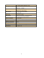
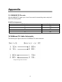
1
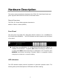
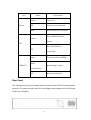
LevelOne
User Manual
FSW-1671
16-Port 10/100 Rackmount Smart Switch w/8 PoE Ports
Ver1.0-0905
FCC Warning
This Equipment has been tested and found to comply with the limits for a Class-A
digital device, pursuant to Part 15 of the FCC rules. These limits are designed to
provide reasonable protection against harmful interference in a residential
installation. This equipment generates, uses, and can radiate radio frequency
energy. It may cause harmful interference to radio communications if the
equipment is not installed and used in accordance with the instructions. However,
there is no guarantee that interference will not occur in a particular installation. If
this equipment does cause harmful interference to radio or television reception,
which can be determined by turning the equipment off and on, the user is
encouraged to try to correct the interference by one or more of the following
measures:
Reorient or relocate the receiving antenna.
Increase the separation between the equipment and receiver.
Connect the equipment into an outlet on a circuit different from that to which
the receiver is connected.
Consult the dealer or an experienced radio/TV technician for help.
CE Mark Warning
This is a Class-A product. In a domestic environment this product may cause radio
interference in which case the user may be required to take adequate measures.
Content
Introduction.................................................................................................................. 1
Features ................................................................................................................ 1
Package Contents ................................................................................................. 2
Hardware Description .................................................................................................. 3
Front Panel ........................................................................................................... 3
LED Indicators ..................................................................................................... 3
Rear Panel ............................................................................................................ 4
Desktop Installation .............................................................................................. 5
Rack-mounted Installation .................................................................................... 5
Power On ............................................................................................................. 5
Web-Based Management .............................................................................................. 6
About Web-based Management ............................................................................ 6
User Login ........................................................................................................... 6
Main Page ............................................................................................................ 8
Administrator ....................................................................................................... 8
Authentication configuration......................................................................... 8
System IP Configuration ............................................................................... 9
System status ...............................................................................................10
Load default setting ..................................................................................... 11
Firmware update .......................................................................................... 11
Reboot device ..............................................................................................13
Port Management ................................................................................................14
Port configuration ........................................................................................14
Port mirroring ..............................................................................................15
Bandwidth Control.......................................................................................16
Broadcast Storm Control ..............................................................................20
VLAN Setting .....................................................................................................22
VLAN Member Setting (Port Based) ...........................................................22
VLAN Mode Setting (Tag Based) ................................................................23
Per Port Counter ..................................................................................................27
Trunk setting .......................................................................................................28
QoS setting ..........................................................................................................30
Priority mode ...............................................................................................30
Class of Service: Physical port, 802.1p ........................................................32
Security Filter ......................................................................................................32
MAC Address Binding .................................................................................32
Miscellaneous ......................................................................................................34
Output queue aging ......................................................................................35
Stride VLAN ...............................................................................................35
IGMP Snooping ...........................................................................................35
Logout .................................................................................................................36
Load default Setting –hardware based..................................................................36
Troubleshooting ..........................................................................................................37
Incorrect connections ...........................................................................................37
Faulty or loose cables...................................................................................37
Non-standard cables .....................................................................................37
Improper Network Topologies .....................................................................37
Diagnosing LED Indicators..........................................................................38
Cabling ........................................................................................................38
Technical Specification ...............................................................................................39
Appendix ....................................................................................................................41
Introduction
Web Smart for Intelligent Networks
FSW-1671 switch is a Web Smart Switch equipped with 16 10/100 Mbps ports with
auto-MDI/MDIX crossover detection function. 8 of those ports are also built with PoE
functionality, providing the ultimate choice in network flexibility. With this added PoE
feature, FSW-1671 is an ideal solution for building wireless, IP surveillance, and VoIP
networks.
Port Trunking, QoS, and Advanced Management
FSW-1671 provides a port-based and 802.1Q tag VLAN function to provide better traffic
management, reduce latency, improve security and save bandwidth.
This is also a
cost-saving feature as it reduces the need to add additional hardware to the network
Power over Ethernet 802.3af
The FSW-1671 has 8 10/100BASE-TX ports that support the IEEE 802.3af PoE
protocol. Each port and transmit a maximum power 15.4W per port. You can also
enable or disable power supply on PoE ports from UI.
Features
- 16×10/100Mbps Auto-negotiation Fast Ethernet RJ45 ports including 8 POE
ports (port-9 ~ port-16)
- Complies with IEEE802.3af standard
- Supports PoE power maximum 15.4W for each PoE port
- Supports IEEE 802.3x flow control for full-duplex mode ports
- Supports back-pressure flow control for half-duplex mode ports
- Each port supports auto MDI/MDIX, so there is no need to use cross-over
Cables or an up-link port
- Supports 802.1Q VLAN
- Supports Port based/802.1P based QoS (Quality of Service)
- Support port base Trunking
- Support Port-Mirroring
- Support Port-setting for Speed/ half/full-Duplex
- Support Port base bandwidth rate control(ingress rate and egress rate)
- Easy configuration via WEB browser
- Support 4K Mac Address Table
- Standard 19” Rack-mount size
1
Package Contents
Unpack the package of FSW-1671 Smart Switch and verify them against the checklist
below:
FSW-1671 Web Smart Switch
Power Cord
Rack-mount brackets
User Manual CD
Compare the contents of FSW-1671 Web Smart Switch package with the standard
checklist above. If any item is missing or damaged, please contact the local dealer for
exchanging.
2
Hardware Description
This section mainly describes the hardware of the FSW-1671 Web Smart Switch and
gives a physical and functional overview on the certain switch
Physical Dimensions
The FSW-1671 Smart Switch physical dimensions is
440mm x 220mm x 44mm (WxDxH)
Front Panel
The front panel of the FSW-1671 Web Smart Switch consists of 16 x 10/100Base-TX
RJ-45 ports (Auto MDI/MDIX).
The LED Indicators are also located on the front panel
of the switch.
RJ-45 Ports (Auto MDI/MDIX): 16 x 10/100 N-way auto-sensing for 10Base-T or
100Base-TX connections.
In general, MDI means connecting to another Hub
or Switch while MDIX means connecting to a workstation or PC. Therefore, Auto
MDI/MDIX would allow connecting to another Switch or workstation without
changing non-crossover or crossover cabling.
LED Indicators
The LED Indicators display real-time information of systematic operation status. The
following table provides descriptions of LED status and their meaning.
3
LED
Power
Status
Description
Yellow
Power On
Off
Power is not connected
Blink
Reset Button for 3 seconds
Port is linked to Power
Yellow
Device
PoE
No Power Device is
Off
connected
Green
LINK/ACT
The port works in 10/100
Blinks
Networking is active
(continuously)
Off
No device attached
Rear Panel
The 3-pronged power plug is located at the rear panel of the FSW-1671 switch shown
as below. The switch will work with AC in the voltage range between 90V to 260V and
Frequency of 50-60Hz
4
Desktop Installation
Set the switch on a sufficiently large flat space with a power outlet nearby. The surface
where the user put the switch should be clean, smooth, level and sturdy. Make sure
there is enough clearance around the switch to allow attachment of cables, power cord
and allow air circulation.
Rack-mounted Installation
The FSW-1671 Web Smart Switch comes with a rack-mounted kit and can be mounted
in an EIA standard size, 19-inch Rack. The switch can be placed in a wiring closet with
other equipment.
Perform the following steps to rack mount the switch:
A.
Position one bracket to align with the holes on one side of the switch and
secure it with the smaller bracket screws. Then attach the remaining bracket
to the other side of the switch.
B.
After having attached mounting brackets, position the FSW-1671 Web Smart
Switch in the rack by lining up the holes in the brackets with the appropriate
holes on the rack. Secure the switch to the rack with a screwdriver and the
rack-mounting screws.
[NOTE] For proper ventilation, it allows about at least 4 inches (10 cm) of
clearance on the front and 3.4 inches (8 cm) on the back of the Switch. This is
especially important for enclosed rack installation.
Power On
Connect the power cord to the power socket on the rear panel of the Switch. The other
side of power cord connects to the power outlet. The internal power supply of the Switch
works with voltage in the range of 90-260VAC and Frequency of 50~60Hz. Check the
power indicator on the front panel to see if power is properly supplied.
5
Web-Based Management
This section introduces the configuration and functions of the Web-Based management.
About Web-based Management
An embedded HTML web site resides in flash memory on the CPU board of the switch.
It offers advanced management features and allows users to manage the switch from
anywhere on the network through a standard browser such as Microsoft Internet
Explorer.
The Web-Based Management supports Internet Explorer 6.0. It is based on Java
Applets with an aim to reduce network bandwidth consumption, enhance access speed
and present an easy viewing screen.
The Web management only allows one person to log in at the same time. With the first
user logging, the system will force him to be logged out when the second user tries to
log in the system.
Notice:
FSW-1671 smart switch support browser IE 6.0 – 7.0 / Firefox 2.0-3.0
User Login
1.
Launch the Internet Explorer.
2.
Key in 192.168.1.1 on the Web Browser
(Note: Make sure you have set fix IP on network adapter)
3.
The login screen appears.
4.
Key in ID & Password. The default login ID and password are “admin”.
5.
Click “OK” then the main page of Web-based management appears
6
Note: It will show error message if you key in wrong user name or password
7
Main Page
Administrator
Administrator includes Authentication Configuration/System IP Configuration/
System Status/ Load default setting/Firmware Update/ Reboot Device
Authentication configuration
Change web management login user name and password for the management security
issue.
1.
Username: Type in the new user name (The default value is ‘admin’).
2.
Password: Type in the new password (The default value is ‘admin’).
3.
Confirm password: Re-type the new password.
4.
And then, click
8
Note:
Username & Password only accept "a-z","A-Z","0-9","-","_"
System IP Configuration
This page shows system configuration including the current IP address and sub-net
mask and Gateway.
User can configure the IP settings, Subnet Mask, Gateway as below:
IP address: Manually assign the IP address that the network is using.
default IP is 192.168.1.1
Subnet Mask : Assign the subnet mask to the IP address
9
The
Gateway: Assign the network gateway for industrial switch.
The default
gateway is 192.168.1.254
If you change the IP address of this switch and then press, “update”
It will show “update successfully” then press Reboot button.
It will enter user
log in screen automatically
System status
This page displays the information about the switch’s MAC address, how many ports it
has, system version and kernel version. Besides, users can also fill in up to 12
characters in the Comment field for note.
MAC Address: Displays the unique hardware address assigned by
manufacturer (default).
Number of Ports: Displays how many ports are there in the switch.
Comment: Users can fill in up to 12 characters in this field. Click the Update
button to save the comments.
System Version: Displays the switch’s firmware version
And then click “Update” button
10
Load default setting
Clicking the “load” button will make the switch being set to the original configuration.
Note: It exclude to change user name, password and IP configuration.
If you want to restore default setting including IP and user name password , then you
can press the reset button for hardware base reset.
More for detail information, you
can refer to Load Default Setting –Hardware Base.
Firmware update
Before the firmware update procedure is executed, you should enter the password twice
and then press “update” button. The smart switch will erase the flash memory. There is
a self-protection mechanism in the Boot Loader, so the Boot Loader will keep intact.
Even though the power is turned off or the cable link fails during the firmware update
procedure, the Boot loader will restore the code to firmware update page.
11
After pressing update button, the old web code will be erased.
Then you can select the image file and press “update” button to update the firmware
you need..
12
TFTP firmware update
Users can get into the command prompt window to proceed. The command prompt
window can be opened by entering “cmd” (without quotes) into Start-Run or through
Start-All Programs-Accessories.
A black and white window ( the color can be
changed) containing the command prompt will open.
Type in “tftp-I 192.168.1.1 put
xxx.bin” (xxx means the file name of the firmware) and press enter to update
Reboot device
Click “Confirm” button to reboot the device.
13
Note:
The reboot is for software base instead of hardware base.
Port Management
Port Management includes Port Configuration, Port Mirroring , Bandwidth Control,
Broadcast Storm Control and PoE
Port configuration
In Port Configuration, you can set and view the operation mode for each port.
Auto-Negotiation: Enable and Disable. Being set as ‘Enable’, the Speed, Duplex
mode, Pause, Backpressure, TX Capability and Address Learning are
negotiated automatically. When you set it as ‘Disable’, you have to assign those
items manually.
Speed: When the Auto-Negotiation column is set as Disable, users have to set the
connection speed to the ports ticked.
Duplex: When the Auto-Negotiation column is set as Disable, users have to set the
connection mode in Half/Full to the ports ticked.
Pause: Flow Control for connection at speed of 10/100Mbps in Full-duplex mode.
14
Backpressure: Flow Control for connection at speed of 10/100Mbps in Half-duplex
mode.
TX Capability: When the Auto-Negotiation column is set as Disable, users have to
set this column as Enable or Disable.
Addr. Learning: When the Auto-Negotiation column is set as Disable, users have
to set this column as Enable or Disable.
Select Port No.: Tick the check boxes beside the port numbers being set.
Click Update to have the configuration take effect.
Current Status: Displays current port status.
Setting Status: Displays current.
Click
Update
to make the configuration effective.
Port mirroring
The Port mirroring is a method for monitoring traffic in switched networks. That Traffic
through ports can be monitored by any of the ports means traffic goes in or out
monitored (source) ports will be duplicated into mirroring (destination) port.
Dest Port: Tick the check boxes beneath the port number label to be the
destination (mirroring) port for monitoring Rx only, Tx only or both RX and TX traffic
which come from the source port. Users can connect the mirroring port to LAN
analyzer or Netxray.
15
Monitored Pckets: Pull down the selection menu to choose what kind of packet is
to be monitored.
Source Port: The ports that the user wants to monitor. All monitored port traffic will
be copied to mirroring (destination) port. Users can select multiple source ports
by ticking the check boxes beneath the port number label to be monitored.
And then, click Update to have the configuration take effect.
Take the following configuration as an example.
(a) Source port: Port 1 ~ Port 4.
(b) Destination Port: Port 9 ~Port 12.
(c) Mirrored packet: Rx.
This means all packets received at port 1 ~port 4 will be copied to port 9, port 10, port 11
and port 12.Care should be taken that the more source ports and destination ports is set,
the lower network throughput is available for normal traffic.
Bandwidth Control
This page allows the setting of the bandwidth for each port. The Tx rate and Rx rate can
be filled with the number ranging from 1 to 255. This number should be multiplied by the
16
selected bandwidth resolution to get the actual bandwidth.
(a) Low bandwidth for TX
Example 1: The TX number of the port1~4 is set to 10, 20, 30, 40 respectively, and
Speed base is set to “low”. The real bandwidth comes from the formula of 32Kbps*10,
32Kbps*20 and 32Kbps*30 respectively. After the “update” button is executed, the real
bandwidth will show up in TX fields.
(b) High bandwidth for TX
17
Example 2: The TX number of the port1~4 is set to 10, 20, 30, 40 respectively, and
Speed base is set to “High”. The real bandwidth comes from the formula of 512Kbps*10,
512Kbps*20 and 512Kbps*30 respectively. After the “update” button is executed, the
real bandwidth will show up in TX fields.
(c) Low bandwidth for Rx
18
Example 3: The RX bandwidth number of the port 5~ port 8 is set to 50, 60, 70, 80
respectively, and Speed base is set to “low”. The real bandwidth comes from the
formula of 32Kbps*50, 32Kbps*60, 32Kbps*70 and 32Kbps*80 respectively After the
“update” button is executed, the real bandwidth will show up in RX fields.
(d) High bandwidth for RX
Example 4: The RX bandwidth number of the port 5~ port 8 is set to 50, 60, 70, 80
respectively, and Speed base is set to “high”. The real bandwidth comes from the
formula of 32Kbps*50, 32Kbps*60, 32Kbps*70 and 32Kbps*80 respectively. After the
“update” button is executed, the real bandwidth will show up in RX fields.
The limitation of the bandwidth control
•
The actual bandwidth should be less than the cable link speed. For 100Mbps link
speed, the bandwidth setting should be less than 196 if the bandwidth is set to
“high”. For 10Mbps link speed, the bandwidth setting should be less than 20 if the
bandwidth base is set to “high”.
•
Setting the bandwidth to “0” means no bandwidth control,
it will run at the
full speed.
The warning message will shows up if bandwidth setting is higher than maximum rate
(100Mbps).
19
Broadcast Storm Control
The switch implements a broadcast storm control mechanism. Tick the check boxes to
have them beginning to drop incoming broadcast packets if the received broadcast
packet counts reach the threshold defined. Each port’s broadcast storm protection
function can be enabled individually by ticking the check boxes.
20
The broadcast packet is only checked at the selected port and the number of broadcast
packets is counted in every time unit. One time unit is 500 us for 10Mbps speed and
5ms for 100Mbps. The excessive broadcast packet will be discarded. For those
broadcast packets incoming from the un-selected port, the switch treats it as the normal
traffic.
Threshold: Type in the threshold in the range between 1 and 63 to limit the
maximum byte counts, which a port can send or receive in a period of time.
Enable Port: Having ticked the boxes, the port will stop transmitting or receiving
data when their sending byte counts or receiving byte counts reach the defined
threshold.
Click Update to have the configuration take effect.
Example:
The broadcast storm of the port1~ port 8 are enabled and the threshold is set to 10. The
broadcast packets will be dropped when number of broadcast packets are more than
the threshold (packet length is 64 bytes).
21
VLAN Setting
A Virtual LAN (VLAN) is a logical network grouping that limits the broadcast domain,
which would allow you to isolate network traffic, so only the members of the same VLAN
will receive traffic from the ones of the same VLAN. Basically, creating a VLAN from a
switch is logically equivalent of reconnecting a group of network devices to another
Layer 2 switch. However, all the network devices are still plugged into the same switch
physically.
VLAN Member Setting (Port Based)
The switch provides port based VLAN configuration. Users can enable the function via
VALN member setting. That is a set of ports allowed to be forwarded from the source
port. The overall number of VLAN groups that this switch can support is 16.
Port: Pull down the selection menu item and choose a number to define a VLAN
Read: Users might want to edit an existent VLAN by selecting the VLAN number and
then click read button to display the member ports of the VLAN.
Dest PORT: The label of each port.
Select: Tick the check boxes to have the ports being the members of the
VLAN. Click Update to have the configuration take effect.
VLAN MEMBER: Displays the member ports for all the ports.
22
VLAN Mode Setting (Tag Based)
Tagged-based VLAN is an IEEE 802.1Q specification standard. Therefore, it is possible
to create a VLAN across devices from different switch venders. IEEE 802.1Q VLAN
uses a technique to insert a “tag” into the Ethernet frames. Tag contains a VLAN
Identifier (VID) 1-4094 that indicates the VLAN numbers. Please notice that this page is
only for Tag Based VLAN.
23
VLAN Mode: Displays VLAN mode: port based/Tag based VLAN
(a) “Add tag” means the outgoing packet of the selected port will be inserted a
802.1Q tag if the packet received at the source port does not include 802,1Q
tag.
(b) “Don’t care” means the outgoing packet of the selected port keep the original
packet received at the source port.
(c) “Remove tag’’ means the 802.1Q tag of the outgoing packet of the selected port
will be stripped if the incoming packet received at the source packet contains
802.1Q tag.
Note: In tag based VLAN mode, it will show error message as below if you add tag
on the port of the NIC which is not support VLAN tag.
24
Tag based VLAN
Add a VLAN: Enter a VID, select the VLAN member and click the VID source port.
Finally press “add” button. The VLAN will be added to the list.
Read (Update) a VLAN: Click the VID, the VLAN member will show up automatically.
Delete a VLAN: After read a VLAN, just press “delete” to remove a VLAN.
Modify a VLAN: After read a VLAN, select the VLAN member and VID source port and
then press “update”.
25
Example: Create two VLAN groups which share port 3 on VLAN 1(port 1 to port
3) and VLAN2 (port 3 to port 6) by port base & tag base VLAN.
Assume port 3
is connected to Server for two VLAN groups to access data.
1. Port Base:
Select Dest PORT 1,2,3 on Port 1
Select Dest PORT 1,2,3 on Port 2
Select Dest PORT 1,2,3,4,5 on Port 3
Select Dest PORT 3,4,5 on Port 4
Select Dest PORT 3,4,5 on Port 5
2. Tag Base:
Add VID 10 on VLAN member port 1 ,2 ,3 and select VID source port
on port 1,2
Add VID 20 on VLAN member port 3,4, 5 and select VID source port
on port 4, 5
26
Per Port Counter
This page provides port counter of each port. There are 4 cateogries :Receive Packet
& Transmit Packet/ Transmit & Collision / Receive Packet & Drop /Receive & CRC
error.
Once you change the counter category, the counter will be cleared
automatically.
Receive packet & Transmit packet:
This category shows both the received packet
count(excluding the incorrect packet) and the transmitted packet count.
Transmit packet & collision:
This category shows the packets outgoing from the
switch and the count of collision.
Receive packet & Drop packet: This category shows the number of received valid
packet and the number of dropped packet.
Receive packet & CRC packet: This category shows the received correct packet and
received CRC error.
Refresh: Press “Refresh” button will aggregate the number of the counter for all ports.
Clear: Press “clear” will clear all counters.
27
Trunk setting
Port trunk allows multiple links to be bundled together and act as a single physical link
for increased throughput. It provides load balancing, and redundancy of links in a
switched inter-network. Actually, the link does not have an inherent total bandwidth
equal to the sum of its component physical links. Traffic in a trunk is distributed across
an individual link within the trunk in a deterministic method that called a hash algorithm.
The hash algorithm automatically applies load balancing to the ports in the trunk. A port
failure within the trunk group causes the network traffic to be directed to the remaining
ports. Load balancing is maintained whenever a link in a trunk is lost or returned to
service. This switch may use Port ID, Source MAC Address, Destination MAC Address,
or a combination of Source MAC Address and Destination MAC Address to be the
selection for Trunk Hash Algorithm. Traffic pattern on the network should be considered
carefully before applying it. When a proper hash algorithm is used, traffic is kind of
randomly decided to be transmitted across either link within the trunk and load
balancing will be seen.
FSW-1671 smart switch supports two trunk group, each trunk consists of 2~4 ports.
Trunk hash algorithm can be selected according to 4 different methods.
28
Port ID: Among the trunk member ports, the packet will be distributed based on the port
ID.
SA: Among the trunk member ports, the packet will be distributed based on the source
MAC address.
DA: Among the trunk member ports, the packet will be distributed based on the
destination MAC address.
DA&SA: Among the trunk member ports, the packet will be distributed based on the
XOR calculation result of the source MAC address and the destination MAC address.
Note:
You can’t trunk which consists of more than one VLAN in the same trunk group.
It will show you the error message if you don’t follow the rule as below.
29
QoS setting
Here you can configure QoS policy priority mode and CoS (Class of Service)
configuration. QoS (Quality of Service) refers to mechanisms in the network software
that make the actual determination of which packets have priority. CoS refers to feature
sets, or groups of services, that are assigned to users based on company policy. If a
feature set includes priority transmission, then CoS winds up being implemented in QoS
functions within the routers and switches in the network. In an enterprise network, class
of service (CoS) differentiates high-priority traffic from lower-priority traffic. Tags may be
added to the packets to identify such classes, but they do not guarantee delivery as do
quality of service (QoS) functions, which are implemented in the network devices.
Priority mode
There are three priority modes available to specify the priority of packets being serviced.
Those include First-In-First-Out, All-High-Before-Low, and Weight-Round-Robin.
30
First-In-First-Out: Packets are placed into the queue and serviced in the order they
were received.
All-high-before-low(Strict priority):
:
All packets will be assigned to either high priority queue (Queue 2) or low priority queue
(queue 1). The packet on the low priority queue will not be forwarded until the high
priority queue is empty.
WRR mode
There are 4 priority queues for Weighted-and-round-robin (WRR) mode. When this
mode is selected, the traffic will be forwarded according to the number set in each
queue.
Example: If Q1 ~ Q4 are set to 5, 3, 2, 8, then the traffic at the specific port will go out in
the following sequence. 8 packets stored in queue 4, 2 packets in queue 3, 3 packets
stored in queue 2, 5 packets stored in queue 1, 5 packets stored in queue 1 ……
31
Class of Service: Physical port, 802.1p
There are 2 types of CoS for this setting; 802.1p and physical port. The user can select
more than one item for each port.
Please note that if more than one type of CoS is selected, the switch will arrange the
packet to the assigned queue according the following priority:
1st
802.1p
2nd physical port
For 802.1p priority, the following table is used to map the 802.1p field to the priory
queue.
Priory Field
Priority Queue
6, 7
Q4
4,5
Q3
0,3
Q2
1,2
Q1
Security Filter
FSW-1671 provides MAC Address Binding security filter.
MAC Address Binding
Port No: Displays the port number being assigned the MAC addresses.
MAC Address: Users can assign up to 3 MAC addresses to the port.
Read: Pull down the selection bar to choose a port number and click the read button to
show the MAC addresses bound with the port or modify the MAC addresses.
32
Select Port: Pull down the selection menu bar to choose a port number to be set.
Binding: Enable or disable the binding function. Click Update to have the
configuration take effect.
Note: Setting the multicast MAC address to these fields is not allowed.
Backup/Recovery
This function provides the user with a method to backup/recovery the switch
configuration. The user can save configuration file to a specified file. If the user wants to
recover the original configuration, which is saved at the specified path, just enter the
password and then press the “upload” button. Finally the original configuration of the
switch will be recovered.
33
Note:
It will show below error message if the file format you uploaded is not correct.
Miscellaneous
Miscellaneous setting is used to configure output queue aging time, VLAN stride and
IGMP snooping.
34
Output queue aging
This function is used to avoid the poor utilization of the switch. When a packet is stored
in a switch for a long time, it will expire from the allowable time defined by the protocol
and become a useless packet. To prevent these packets from wasting the bandwidth,
this switch provide an option for the administrator to enable the queue aging function.
Stride VLAN
By selecting this function, the switch will forward uni-cast packets to the destination port,
no matter whether destination port is in the same VLAN.
IGMP Snooping
When this function is enabled, the switch will execute IGMP snooping version 1 and
version 2 without the intervention of CPU.
The IGMP report and leave packets are automatically handled by the switch.
35
Logout
It will logout from User Interface when you press the it.
Load default Setting –hardware based
The purpose of this function is to provide a method for the network administrator to
restore all configurations to the default value.
(1) To activate this function, the user should follow the following procedures. Press the
“Load default” button for 3 seconds until you see the LED blinking.
(2) When LED starts blinking, it means the CPU is executing the “load default”
procedure. You can release the button now.
After completing this procedure, all the factory default value will be restored. It
includes the IP address, the user name, the password and all switch configurations.
36
Troubleshooting
This section is intended to help the user solve the most common problems on the
FSW-1671 Web Smart Switch.
Incorrect connections
The switch port can auto-detect straight or crossover cable when the user links switch
with other Ethernet device. The RJ-45 connector should use correct UTP or STP cable.
10/100Mbps ports use 2 pairs twisted cable and Gigabit 1000T ports use 4 pairs twisted
cable. If the RJ-45 connector is not correctly pinned on right position then the link will
fail. For fiber connection, please notice that fiber cable mode should match the fiber
module
.
Faulty or loose cables
Look for loose or obviously faulty connections. If they appear to be OK, make sure
the connections are snug. If that does not correct the problem, try a different cable.
Non-standard cables
Non-standard and miss-wired cables may cause numerous network collisions and other
network problem, and can seriously impair network performance. A category 5-cable
tester is a recommended tool for every 100Base-T network installation.
Improper Network Topologies
It is important to make sure that users have a valid network topology. Common topology
faults include excessive cable length and too many repeaters (hubs) between end
nodes. In addition, the user should make sure that the network topology contains no
data path loops. Between any two ends nodes, there should be only one active cabling
37
path at any time. Data path loops will cause broadcast storms that will severely impact
the network performance.
Diagnosing LED Indicators
To assist in identifying problems, the switch can be easily monitored through panel
indicators, which describe common problems the user may encounter and where the
user can find possible solutions.
If the power indicator does turn on when the power cord is plugged in, the user may
have a problem with power outlet, or power cord. However, if the switch powers off after
running for a while check for loose power connections, power losses or surges at power
outlet. If the problem still cannot be resolved, please contact the local dealer for
assistance.
Cabling
RJ-45 ports: Use unshielded twisted-pair (UTP) or shielded twisted-pair (STP) cable
for RJ-45 connections: 100Ω Category 3, 4 or 5 cable for 10Mbps connections or 100
Ω Category 5 cable for 100Mbps connections. Also be sure that the length of any
twisted-pair connection does not exceed 100 meters (328 feet). Gigabit port should use
Cat-5 or cat-5e cable for 1000Mbps connections. The length does not exceed 100
meters.
38
Technical Specification
For more detail specification , you can refer below table :
Standards
IEEE 802.3af
IEEE 802.3 10BaseT
IEEE 802.3u 100BaseTX
IEEE 802.3x Flow Control in full duplex
IEEE 802.1p QoS
IEEE 802.1Q VLAN Tag
IEEE 802.3af Power Over Ethernet
Features
Number of Ports: 16 10/100BaseT(X) with 8 PSE/Power
over Ethernet Ports
MAC Address: 4K
Buffer Memory: 1.5 Mb
Transmission Method: Store and Forward
Smart Features
Security Filter:
MAC Address Binding
VLAN Setting:
Port Based VLAN
Tag Based VLAN ( 20 entries )
VLAN ID (Up to 4094K )
QoS:
Priority ( Port Based / 802.1p)
Management:
Password-protected Access,
On /Off PoE Port Settings,
Web-base Management,
Graphic User Interface
Bandwidth Control
Broadcast Storm Control
Port Mirroring
Port Configuration
Programmable aging timer
IGMP Snooping v1/ v2
Trunk ( 4 Ports per Group, 2 Group per Device )
39
Firmware Update ( Web Base / TFTP )
Filtering/Forwarding Rates
100Mbps port - 148,800pps
10Mbps port - 14,880pps
Transmission Media
10BaseT Cat. 3, 4, 5 UTP/STP
100BaseTX Cat. 5/5e UTP/STP
LED Indicators
Per Port: Link/Act, PoE Act/Status
Per Unit: Power
Power Input
90~260V/AC, 50~60Hz
Power Output
48V/DC Per Port Output – 15.4 W Max Per Port
8 Ports at Full 15.4 W Output Supported
Power Consumption
130 Watts (Max)
Dimensions
440 × 220 × 44 mm (L x W x H)
Weight
3.8 kg
Operating Temperature
0 to 60℃
Storage Temperature
-20 to 90℃
Humidity
10 to 90% RH (non-condensing)
Certifications
FCC Class A, CE
40
Appendix
10 /100BASE-TX Pin outs
With10/100BASE-TX cable, pins 1 and 2 are used for transmitting data, and pins 3
and 6 for receiving data.
RJ-45 Pin Assignments
Pin Number
Assignment
1
Tx+
2
Tx-
3
Rx+
6
Rx-
10/100Base-TX Cable Schematic
The following two figures show the 10/100Base-TX cable schematic
Straight-through cable schematic
41
Cross over cable schematic
42