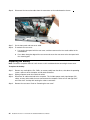
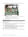
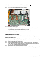
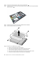
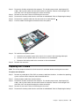
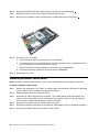
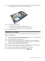
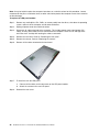
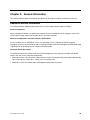
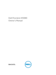
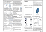
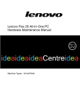
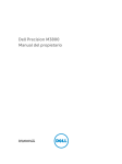
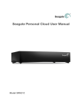
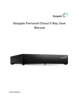
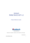
1
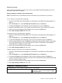
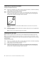
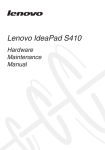
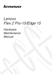
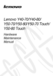
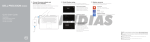
IdeaCentre Horizon 2 27 All-In-One PC
Hardware Maintenance Manual
Machine Types: F0AQ
IdeaCentre Horizon 2 27 All-In-One PC
Hardware Maintenance Manual
Machine Types: F0AQ
Second Edition (May 2014)27th
© Copyright Lenovo 2014.
LIMITED AND RESTRICTED RIGHTS NOTICE: If data or software are delivered pursuant a General Services
Administration “GSA” contract, use, reproduction, or disclosure is subject to restrictions set forth in Contract No.
GS-35F-05925
Contents
Chapter 1. About this manual . . . . . . 1
Important Safety Information . . . . . . . . . .
1
Chapter 2. Safety information . . . . . . 3
General safety . . . . . . . . . . . .
Electrical safety . . . . . . . . . . .
Safety inspection guide . . . . . . . .
Handling electrostatic discharge-sensitive
devices . . . . . . . . . . . . . .
Grounding requirements . . . . . . . .
Safety notices . . . . . . . . . . . .
. . . .
. . . .
. . . .
3
3
5
. . . .
. . . .
. . . .
5
6
6
Chapter 3. General information . . . . . 9
Specifications . . . . . . . . . . . . . . . .
9
Chapter 4. General Checkout . . . . .
11
Chapter 5. Using the Setup Utility. . .
13
Starting the Lenovo BIOS Setup Utility program
Viewing and changing settings . . . . . . .
Using passwords. . . . . . . . . . . . .
Enabling or disabling a device . . . . . . .
Selecting a startup device . . . . . . . . .
Exiting the Lenovo BIOS Setup Utility program .
.
.
.
.
.
.
13
13
13
15
16
17
Chapter 6. Symptom-to-FRU Index . .
19
Hard disk drive boot error . . . . . . . . . .
19
© Copyright Lenovo 2014
Power Supply Problems . . . . . . . . . . .
POST error codes . . . . . . . . . . . . .
Undetermined problems . . . . . . . . . . .
19
20
20
Chapter 7. Replacing hardware . . . .
21
General information . . . . . . .
Replacing the keyboard and mouse
Removing the rear cover . . . . .
Replacing the battery . . . . . .
Replacing a memory module . . .
Replacing the Wi-Fi card. . . . .
Replacing the hard disk drive . . .
Replacing the fan module . . . .
Replacing the heat-sink modules .
Replacing the speaker system . .
Replacing the I/O board . . . . .
Replacing the power switch board .
Replacing the motherboard. . . .
Replacing the camera . . . . . .
Replacing the LED panel module .
.
.
.
.
.
.
.
.
.
.
.
.
.
.
.
21
22
22
24
25
26
27
29
29
30
31
32
33
34
35
Chapter 8. FRU lists . . . . . . . . . .
37
Chapter 9. General information . . . .
43
Additional Service Information
.
.
.
.
.
.
.
.
.
.
.
.
.
.
.
.
.
.
.
.
.
.
.
.
.
.
.
.
.
.
.
.
.
.
.
.
.
.
.
.
.
.
.
.
.
.
.
.
.
.
.
.
.
.
.
.
.
.
.
.
.
.
.
.
.
.
.
.
.
.
.
.
.
.
.
. . . . . . . .
43
iii
iv
IdeaCentre Horizon 2 27 All-In-One PC Hardware Maintenance Manual
Chapter 1. About this manual
This manual contains service and reference information for IdeaCentre Horizon 2 27 All-In-One computers
listed on the cover. It is intended only for trained servicers who are familiar with Lenovo computer products.
Before servicing a Lenovo product, be sure to read the Safety Information.
The description of the TV-tuner card in this manual applies only to computers with a TV-tuner card installed.
It does not apply to computers without a TV-tuner card.
Important Safety Information
Be sure to read all CAUTION and DANGER sections in this manual before following any of the instructions.
Veuillez lire toutes les consignes de type DANGER et ATTENTION du présent document avant d’exécuter
les instructions.
Lesen Sie unbedingt alle Hinweise vom Typ “ACHTUNG” oder “VORSICHT” in dieser Dokumentation, bevor
Sie irgendwelche Vorgänge durchführen
Leggere le istruzioni introdotte da ATTENZIONE e PERICOLO presenti nel manuale prima di eseguire una
qualsiasi delle istruzioni
Certifique-se de ler todas as instruções de cuidado e perigo neste manual antes de executar qualquer
uma das instruções
Es importante que lea todas las declaraciones de precaución y de peligro de este manual antes de seguir
las instrucciones.
© Copyright Lenovo 2014
1
2
IdeaCentre Horizon 2 27 All-In-One PC Hardware Maintenance Manual
Chapter 2. Safety information
This chapter contains the safety information that you need to be familiar with before servicing a computer.
General safety
Follow these rules to ensure general safety:
• Keep the areas around the computer clear and clean during and after maintenance.
• When lifting any heavy object:
1. Ensure you can stand safely without slipping.
2. Distribute the weight of the object equally across both feet.
3. Lift slowly. Never move suddenly or twist when you attempt to lift.
4. Lift by standing or by pushing up with your leg muscles; this action removes the strain from the
muscles in your back.
Do not attempt to lift any objects that weigh more than 16 kg (35 lbs.) or objects that you think
are too heavy for you.
• Do not perform any action that would create a hazard for the customer, or would make the computer
unsafe.
• Before you start the computer, ensure that other service representatives and customer personnel are not
in a position that would create a hazard for them.
• Place removed covers and other parts in a safe place, away from all personnel, while you are servicing the
computer.
• Keep your tool case away from areas that people may walk through to ensure no-one trips over it.
• Do not wear loose clothing that can be trapped in the moving parts of a machine. Ensure that your sleeves
are fastened or rolled up above your elbows. If your hair is long, tie or fasten it back.
• Insert the ends of your necktie or scarf inside clothing or fasten it with a nonconductive clip, approximately
8 centimeters (3 inches) from the end.
• Do not wear jewelry, chains, metal-frame eyeglasses, or metal fasteners for your clothing.
Remember: Metal objects are good electrical conductors.
• Wear safety glasses when you are: hammering, drilling soldering, cutting wire, attaching springs, using
solvents, or working in any other conditions that might be hazardous to your eyes.
• After service, reinstall all safety shields, guards, labels, and ground wires. Replace any safety device
that is worn or defective.
• Reattach all covers correctly before returning the computer to the customer.
Electrical safety
CAUTION:
Electrical current from power, telephone, and communication cables can be hazardous. To avoid
personal injury or equipment damage, disconnect any attached power cords, telecommunication
cables, network cables, and modem cables before you open the computer covers, unless instructed
otherwise in the installation and configuration procedures.
© Copyright Lenovo 2014
3
Observe the following rules when working on electrical equipment.
Important: Use only approved tools and test equipment. Some hand tools have handles covered with a soft
material that does not insulate you when working with live electrical currents. Many customers have rubber
floor mats near their equipment that contain small conductive fibers to decrease electrostatic discharge.
• Find the room emergency power-off (EPO) switch, disconnecting switch, or electrical outlet. If an electrical
accident occurs, you can then operate the switch or unplug the power cord quickly.
• Do not work alone under hazardous conditions or near equipment that has hazardous voltages.
• Disconnect all power before:
– Performing a mechanical inspection
– Working near power supplies
– Removing or installing Field Replaceable Units (FRUs)
• Before you start to work on the computer, unplug the power cord. If you cannot unplug it, ask the
customer to power-off the electrical outlet that supplies power to the machine and to lock the electrical
outlet in the off position.
• If you need to work on a computer that has exposed electrical circuits, observe the following precautions:
– Ensure that another person, familiar with the power-off controls, is near you.
Remember: Another person must be there to switch off the power, if necessary.
– Use only one hand when working with powered-on electrical equipment; keep the other hand in your
pocket or behind your back.
Remember: There must be a complete circuit to cause electrical shock. By observing the above rule,
you may prevent a current from passing through your body.
– When using a tester, set the controls correctly and use the approved probe leads and accessories for
that tester.
– Stand on suitable rubber mats (obtained locally, if necessary) to insulate you from grounds such as
metal floor strips and machine frames.
Observe the special safety precautions when you work with very high voltages; these instructions are in
the safety sections of the maintenance information. Use extreme care when measuring high voltages.
• Regularly inspect and maintain your electrical hand tools to ensure they are safe to use.
• Do not use worn or broken tools and testers.
• Never assume that power has been disconnected from a circuit. First, check that it has been powered off.
• Always look carefully for possible hazards in your work area. Examples of these hazards are wet floors,
non-grounded power extension cables, conditions that may cause or allow power surges, and missing
safety grounds.
• Do not touch live electrical circuits with the reflective surface of a plastic dental mirror. This surface is
conductive, and touching a live circuit can cause personal injury and damage to the computer.
• Do not service the following parts with the power on when they are removed from their normal operating
positions in a computer:
– Power supply units
– Pumps
– Blowers and fans
– Motor generators
and similar units. (This practice ensures correct grounding of the units.)
• If an electrical accident occurs:
– Use caution; do not become a victim yourself.
4
IdeaCentre Horizon 2 27 All-In-One PC Hardware Maintenance Manual
– Switch off power.
– Send another person to get medical aid.
Safety inspection guide
The intent of this inspection guide is to assist you in identifying potential hazards posed by these products.
Each computer, as it was designed and built, had required safety items installed to protect users and
service personnel from injury. This guide addresses only those items. However, good judgment should be
used to identify potential safety hazards due to attachment of features or options not covered by this
inspection guide.
If any hazards are present, you must determine how serious the apparent hazard could be and whether you
can continue without first resolving the problem.
Consider the following items and the safety hazards they present:
• Electrical hazards, especially primary power (primary voltage on the frame can cause serious or fatal
electrical shock).
• Explosive hazards, such as a damaged CRT face or bulging capacitor
• Mechanical hazards, such as loose or missing hardware
The guide consists of a series of steps presented as a checklist. Begin the checks with the power off, and
the power cord disconnected.
Checklist:
1. Check exterior covers for damage (loose, broken, or sharp edges).
2. Power-off the computer. Disconnect the power cord.
3. Check the power cord for:
a. A third-wire ground connector in good condition. Use a meter to measure third-wire ground
continuity for 0.1 ohm or less between the external ground pin and frame ground.
b. The power cord should be the appropriate type as specified in the parts listings.
c. Insulation must not be frayed or worn.
4. Remove the cover.
5. Check for any obvious alterations. Use good judgment as to the safety of any alterations.
6. Check inside the unit for any obvious hazards, such as metal filings, contamination, water or other
liquids, or signs of fire or smoke damage.
7. Check for worn, frayed, or pinched cables.
8. Check that the power-supply cover fasteners (screws or rivets) have not been removed or tampered with.
Handling electrostatic discharge-sensitive devices
Any computer part containing transistors or integrated circuits (ICs) should be considered sensitive to
electrostatic discharge (ESD). ESD damage can occur when there is a difference in charge between objects.
Protect against ESD damage by equalizing the charge so that the computer, the part, the work mat, and the
person handling the part are all at the same charge.
Notes:
1. Use product-specific ESD procedures when they exceed the requirements noted here.
2. Make sure that the ESD protective devices you use have been certified (ISO 9000) as fully effective.
When handling ESD-sensitive parts:
Chapter 2. Safety information
5
• Keep the parts in protective packages until they are inserted into the product.
• Avoid contact with other people while handling the part.
• Wear a grounded wrist strap against your skin to eliminate static on your body.
• Prevent the part from touching your clothing. Most clothing is insulative and retains a charge even
when you are wearing a wrist strap.
• Use the black side of a grounded work mat to provide a static-free work surface. The mat is especially
useful when handling ESD-sensitive devices.
• Select a grounding system, such as those listed below, to provide protection that meets the specific
service requirement.
Note: The use of a grounding system is desirable but not required to protect against ESD damage.
– Attach the ESD ground clip to any frame ground, ground braid, or green-wire ground.
– Use an ESD common ground or reference point when working on a double-insulated or
battery-operated system. You can use coax or connector-outside shells on these systems.
– Use the round ground-prong of the AC plug on AC-operated computers.
Grounding requirements
Electrical grounding of the computer is required for operator safety and correct system function. Proper
grounding of the electrical outlet can be verified by a certified electrician.
Safety notices
The CAUTION and DANGER safety notices in this section are provided in the language of English.
DANGER
Electrical current from power, telephone and communication cables is hazardous.
To avoid a shock hazard:
• Do not connect or disconnect any cables or perform installation, maintenance, or reconfiguration
of this product during an electrical storm.
• Connect all power cords to a properly wired and grounded electrical outlet.
• Connect any equipment that will be attached to this product to a properly wired outlet.
• When possible, use one hand only to connect or disconnect signal cables.
• Never turn on any equipment when there is evidence of fire, water, or structural damage.
• Disconnect the attached power cords, telecommunications cables, network cables, and modem
cables before you open the device covers, unless instructed otherwise in the installation and
configuration procedures.
• Connect and disconnect cables as described in the following table when installing, moving, or
opening covers on this product or attached devices.
6
IdeaCentre Horizon 2 27 All-In-One PC Hardware Maintenance Manual
To Connect
To Disconnect
1. Turn everything OFF.
1. Turn everything OFF.
2. First, attach all cables to devices.
2. First, remove power cords from outlets.
3. Attach signal cables to connectors.
3. Remove signal cables from connectors.
4. Attach power cords to outlet.
4. Remove all cables from devices.
5. Turn device ON.
CAUTION:
When replacing the lithium battery, use only Part Number 45C1566 or an equivalent type battery
recommended by the manufacturer. If your system has a module containing a lithium battery, replace
it only with the same module type made by the same manufacturer. The battery contains lithium and
can explode if not properly used, handled, or disposed of.
Do not:
• Throw into or immerse in water
• Heat to more than 100°C (212°F)
• Repair or disassemble
Dispose of the battery as required by local ordinances or regulations.
CAUTION:
When laser products (such as CD-ROMs, DVD-ROM drives, fiber optic devices, or transmitters) are
installed, note the following:
• Do not remove the covers. Removing the covers of the laser product could result in exposure to
hazardous laser radiation. There are no serviceable parts inside the device.
• Use of controls or adjustments or performance of procedures other than those specified herein
might result in hazardous radiation exposure.
DANGER
Some laser products contain an embedded Class 3A or Class 3B laser diode. Note the following:
These diodes emit radiation when open. Do not stare into the beam, do not view directly with
optical instruments, and avoid direct exposure to the beam.
Chapter 2. Safety information
7
≥18 kg (37 lbs)
≥32 kg (70.5 lbs)
≥55 kg (121.2 lbs)
CAUTION:
Use safe practices when lifting.
CAUTION:
The power control button on the device and the power switch on the power supply do not turn off
the electrical current supplied to the device. The device also might have more than one power
cord. To remove all electrical current from the device, ensure that all power cords are disconnected
from the power source.
2
1
CAUTION:
Do not place any object weighing more than 82 kg (180 lbs.) on top of rack-mounted devices.
8
IdeaCentre Horizon 2 27 All-In-One PC Hardware Maintenance Manual
Chapter 3. General information
This chapter provides general information that applies to all computer models covered by this manual.
Specifications
This section lists the physical specifications for your computer.
This section lists the physical specifications for your computer.
Type IdeaCentre Horizon 2 27
This section lists the physical specifications.
Environment
Air temperature:
Operating: 10° to 35°C
Transit: -20° to 55°C
Humidity:
Operating: 35% to 80%
Transit: 20% to 90% (40°C)
Altitude: 86KPa to 106KPa
Electrical input:
Input voltage: 90V-264V(AC)
Input frequency: 47Hz-63Hz
© Copyright Lenovo 2014
9
10
IdeaCentre Horizon 2 27 All-In-One PC Hardware Maintenance Manual
Chapter 4. General Checkout
Attention: The drives in the computer you are servicing might have been rearranged or the drive startup
sequence may have been changed. Be extremely careful during write operations such as copying, saving, or
formatting. Data or programs can be overwritten if you select an incorrect drive.
General error messages appear if a problem or conflict is found by an application, the operating system, or
both. For an explanation of these messages, refer to the information supplied with that software package.
Use the following procedure to help determine the cause of the problem:
1. Power-off the computer and all external devices.
2. Check all cables and power cords.
3. Set all display controls to the middle position.
4. Power-on all external devices.
5. Power-on the computer.
• Look for displayed error codes.
• Look for readable instructions or a main menu on the display.
If you did not receive the correct response, proceed to step 6.
If you did receive the correct response, proceed to step 7.
6. If one of the following happens, follow the instruction given:
• If the computer displays a POST error, go to “POST error codes”.
• If the computer hangs and no error is displayed, continue at step 7.
7. If the test stops and you cannot continue, replace the last device tested.
© Copyright Lenovo 2014
11
12
IdeaCentre Horizon 2 27 All-In-One PC Hardware Maintenance Manual
Chapter 5. Using the Setup Utility
The Setup Utility program is used to view and change the configuration settings of your computer, regardless
of which operating system you are using. However, the operating system settings might override any similar
settings in the Setup Utility program.
Starting the Lenovo BIOS Setup Utility program
To start the Lenovo BIOS Setup Utility program, do the following:
1. If your computer is already on when you start this procedure, shut down the operating system and
turn off the computer.
2. Press and hold the F1 key then turn on the computer. When the Lenovo BIOS Setup Utility program is
displayed, release the F1 key.
Note: If a Power-On Password or an Administrator Password has been set, the Setup Utility program menu
will not be displayed until you type your password. For more information, see “Using passwords.”
Viewing and changing settings
System configuration options are listed in the Lenovo BIOS Setup Utility program menu. To view or change
settings, see “Starting the Setup Utility program.”
You must use the keyboard when using the Lenovo BIOS Setup Utility menu. The keys used to perform
various tasks are displayed on the bottom of each screen.
Using passwords
You can use the Lenovo BIOS Setup Utility program to set passwords to prevent unauthorized persons
from gaining access to your computer and data. See “Starting the Setup Utility program.” The following
types of passwords are available:
• Administrator Password
• Power-On Password
You do not have to set any passwords to use your computer. However, if you decide to set passwords, read
the following sections.
Password considerations
A password can be any combination of letters and numbers up to 16 characters (a-z and 0-9). For security
reasons, it is a good idea to use a strong password that cannot be easily compromised. We suggest that
passwords should follow these rules:
• For a strong password, use 7-16 characters and a mix of letters and numbers.
• Do not use your name or your user name.
• Do not use a common word or a common name.
• Use something significantly different from your previous password.
Attention: Administrator and Power-On passwords are not case sensitive.
© Copyright Lenovo 2014
13
Administrator Password
Setting an Administrator Password deters unauthorized persons from changing configuration settings. You
might want to set an Administrator Password if you are responsible for maintaining the settings of several
computers.
After you set an Administrator Password, a password prompt is displayed every time you access the Lenovo
BIOS Setup Utility program.
If both the Administrator and Power-On Password are set, you can type either password. However, you must
use your Administrator Password to change any configuration settings.
Setting, changing, or deleting an Administrator Password
To set an Administrator Password, do the following:
Note: A password can be any combination of letters and numbers up to 16 characters (a-z and 0-9). For
more information, see “Password considerations” on page 13.
1. Start the Lenovo BIOS Setup Utility program (see “Starting the Lenovo BIOS Setup Utility program” on
page 13).
2. From the Security menu, select Set Administrator Password and press the Enter key.
3. The password dialog box will be displayed. Type the password then press the Enter key.
4. Retype the password to confirm, then press the Enter key. If you typed the password correctly, the
password will be installed. A Setup Notice will be displayed confirming that your changes has been
saved.
5. Return to the Lenovo BIOS Setup Utility program menu and select the Exit option.
6. Select Save Changes and Exit from the menu.
To change an Administrator Password, do the following:
1. Start the Lenovo BIOS Setup Utility program (see “Starting the Lenovo BIOS Setup Utility program” on
page 13).
2. From the Security menu, select Set Administrator Password and press the Enter key.
3. The password dialog box will be displayed. Type the current password then press the Enter key.
4. Type the new password, then press the Enter key. Retype the new password to confirm it. If you typed
the new password correctly, the new password will be installed. A Setup Notice will be displayed
confirming that your changes have been saved.
5. Return to the Lenovo BIOS Setup Utility program menu and select the Exit option.
6. Select Save Changes and Exit from the menu.
To delete a previously set Administrator Password, do the following :
1. Start the Lenovo BIOS Setup Utility program (see “Starting the Lenovo BIOS Setup Utility program” on
page 13).
2. From the Security menu, select Set Administrator Password and press the Enter key.
3. The password dialog box will be displayed. Type the current password and press the Enter key.
4. Leave each new password line item blank, then press the Enter key. A Setup Notice will be displayed
confirming that your changes have been saved.
5. Return to the Lenovo BIOS Setup Utility program menu and select the Exit option.
6. Select Save Changes and Exit from the menu.
14
IdeaCentre Horizon 2 27 All-In-One PC Hardware Maintenance Manual
Power-On Password
When a Power-On Password is set, you cannot start the Lenovo BIOS Setup Utility program until a valid
password is typed from the keyboard.
Setting, changing, or deleting a Power-On Password
Note: A password can be any combination of letters and numbers up to 16 characters (a-z and 0-9).
To set a Power-On Password, do the following:
1. Start the Lenovo BIOS Setup Utility program (see ”Starting the Lenovo BIOS Setup Utility program” on
page 13).
2. From the Security menu, select Set Power-On Password and press the Enter key.
3. The password dialog box will be displayed. Type the password, then press the Enter key.
4. Retype the password to confirm. If you typed the password correctly, the password will be installed.
5. Return to the Lenovo BIOS Setup Utility program menu and select the Exit option.
6. Select Save Changes and Exit from the menu.
To change a Power-On Password, do the following:
1. Start the Lenovo BIOS Setup Utility program (see ”Starting the Lenovo BIOS Setup Utility program” on
page 13).
2. From the Security menu, select Set Power-On Password and press the Enter key.
3. The password dialog box will be displayed. Type the current password then press the Enter key.
4. Type the new password, then press the Enter key. Retype the new password to confirm it. If you typed
the new password correctly, the new password will be installed. A Setup Notice will be displayed
confirming that your changes have been saved.
5. Return to the Lenovo BIOS Setup Utility program menu and select the Exit option.
6. Select Save Changes and Exit from the menu.
To delete a previously set Power-On Password, do the following :
1. Start the Lenovo BIOS Setup Utility program (see ”Starting the Lenovo BIOS Setup Utility program” on
page 13).
2. From the Security menu, select Set Power-On Password and press the Enter key.
3. The password dialog box will be displayed. Type the current password and press the Enter key.
4. Leave each new password line item blank, then press Enter. A Setup Notice will be displayed confirming
that your changes have been saved.
5. Return to the Lenovo BIOS Setup Utility program menu and select the Exit option.
6. Select Save Changes and Exit from the menu.
Enabling or disabling a device
The Devices options is used to enable or disable user access to the following:
USB Functions
Select whether to enable or disable USB (Universal Serial
Bus) functions. If the functions are disabled, no USB
devices can be used.
Chapter 5. Using the Setup Utility
15
SATA Mode
Select Disabled/IDE/AHCI mode. Device driver support
is required for AHCI or RAID. Depending on how the hard
disk drive image was installed, changing this setting may
prevent the system from booting.
Onboard Audio Controller
Select whether to enable or disable the Onboard
Audio Controller. When this feature is set to Disabled
all devices connected to the audio connectors (e.g.
headphones or a microphone) are disabled and cannot
be used.
To enable or disable a device, do the following:
1. Start the Setup Utility program (see “Starting the Setup Utility program” on page 13).
2. From the Setup Utility program menu, select Devices.
3. Select an option as follows:
Select USB Setup, press the Enter key, then select USB Functions.
Select ATA Drivers Setup, press the Enter key, then select SATA Mode.
Select Audio Setup, press the Enter key, then select Onboard Audio Controller.
4. Select Disabled or Enabled and press the Enter key.
5. Return to the Lenovo BIOS Setup Utility program menu and select the Exit option.
6. Select Save Changes and Exit from the menu.
Notes:
a. If you do not want to save the settings, select Discard Changes and Exit from the menu.
Selecting a startup device
If your computer does not boot from a device such as the CD/DVD-ROM drive disk or hard disk as expected,
follow one of the procedures below.
Selecting a temporary startup device
Use this procedure to start up from any boot device.
Note: Not all CDs, DVDs or hard disk drives are bootable.
1. Turn off your computer.
2. Press and hold the F12 key then turn on the computer. When the Startup Device Menu appears,
release the F12 key.
Note: If the Startup Device Menu does not display using these steps, repeatedly press and release the
F12 key rather than keeping it pressed when turning on the computer.
3. Use ↑ and ↓ arrows to select the desired startup device from the Startup Device Menu and press
the Enter key to begin.
Note: Selecting a startup device from the Startup Device Menu does not permanently change the
startup sequence.
Selecting or changing the startup device sequence
To view or permanently change the configured startup device sequence, do the following:
16
IdeaCentre Horizon 2 27 All-In-One PC Hardware Maintenance Manual
1. Start the Lenovo BIOS Setup Utility program (see “Starting the Lenovo BIOS Setup Utility program” on
page 13).
2. From the Lenovo BIOS Setup Utility program main menu, select the Startup option.
3. Press the Enter key, and select the devices for the Primary Boot Sequence. Read the information
displayed on the right side of the screen.
4. Use - and ¯ arrows to select a device. Use the <+> or <-> keys to move a device up or down. Use the
<×> key to exclude the device from or include the device in the boot sequence.
5. Return to the Lenovo BIOS Setup Utility program menu and select the Exit option.
6. Select Save Changes and Exit from the menu.
Notes:
a. If you do not want to save the settings, select Discard Changes and Exit from the menu.
b. If you have changed these settings and want to return to the default settings, select Load Optimal
Defaults from the menu.
Exiting the Lenovo BIOS Setup Utility program
After you finish viewing or changing settings, press the Esc key to return to the Lenovo BIOS Setup Utility
program main menu. You might have to press the Esc key several times. Do one of the following:
• If you want to save the new settings, select Save Changes and Exit from the menu. When the Save
& reset window shows, select the Yes button, and then press the Enter key to exit the Lenovo BIOS
Setup Utility program.
• If you do not want to save the settings, select Discard Changes and Exit from the menu. When the
Reset Without Saving window shows, select the Yes button, and then press the Enter key to exit the
Lenovo BIOS Setup Utility program.
Chapter 5. Using the Setup Utility
17
18
IdeaCentre Horizon 2 27 All-In-One PC Hardware Maintenance Manual
Chapter 6. Symptom-to-FRU Index
The Symptom-to-FRU index lists error symptoms and possible causes. The most likely cause is listed first.
Always begin with Chapter 4, “General Checkout,” on page 11. This index can also be used to help you
decide which FRUs to have available when servicing a computer. If you are unable to correct the problem
using this index, go to “Undetermined problems” on page 20.
Notes:
• If you have both an error message and an incorrect audio response, diagnose the error message first.
• If you cannot run the diagnostic tests or you get a diagnostic error code when running a test but did
receive a POST error message, diagnose the POST error message first.
• If you did not receive any error message look for a description of your error symptoms in the first part of
this index.
Hard disk drive boot error
A hard disk drive boot error can have the following causes.
Error
FRU/Action
The startup drive is not included in the boot sequence
configuration.
Check the configuration and ensure the startup drive is
in the boot sequence.
No operating system is installed on the boot drive.
Install an operating system on the boot drive.
The boot sector on the startup drive is corrupted.
The drive must be formatted. Do the following:
1. Attempt to back up the data on the failing hard disk
drive.
2. Use the operating system to format the hard disk
drive.
The drive is defective.
Replace the hard disk drive.
Power Supply Problems
Follow these procedures if you suspect there is a power supply problem.
Check/Verify
FRU/Action
Check that the following are properly installed:
Reseat connectors
• Power Cord
• On/Off Switch connector
• System Board Power Supply connectors
• Microprocessor connections
Check the power cord.
Power Cord
Check the power-on switch.
Power-on Switch
© Copyright Lenovo 2014
19
POST error codes
Each time you turn the computer on, it performs a series of tests to check that the system is operating
correctly and that certain options are set. This series of tests is called the Power-On Self-Test, or POST.
POST does the following:
• Checks some basic motherboard operations
• Checks that the memory is working correctly
• Starts video operations
• Verifies that the boot drive is working
POST Error Message
Description/Action
Keyboard error
Cannot initialize the keyboard. Make sure the keyboard
is properly connected to the computer and that no keys
are held pressed during POST. To purposely configure
the computer without a keyboard, select Keyboardless
operation in Startup and set the option to Enabled. The
BIOS then ignores the missing keyboard during POST.
Reboot and Select proper Boot device or Insert Boot
Media in selected Boot device
The BIOS was unable to find a suitable boot device. Make
sure the boot drive is properly connected to the computer.
Make sure you have bootable media in the boot device.
Undetermined problems
1. Power-off the computer.
2. Remove or disconnect the following components (if connected or installed) one at a time.
a. External devices (modem, printer, or mouse)
b. Extended video memory
c. External Cache
d. External Cache RAM
e. Hard disk drive
f. Disk drive
3. Power-on the computer to re-test the system.
4. Repeat steps 1 through 3 until you find the failing device or component.
If all devices and components have been removed and the problem continues, replace the system board.
20
IdeaCentre Horizon 2 27 All-In-One PC Hardware Maintenance Manual
Chapter 7. Replacing hardware
Attention: Do not remove the computer cover or attempt any repair before reading the “Important safety information”
in the Safety and Warranty Guide that was included with your computer. To obtain copies of the Safety and Warranty
Guide, go to the Support Web site at: http://support.lenovo.com.
Note: Use only parts provided by Lenovo.
General information
Pre-disassembly instructions
Before starting the disassembly procedure, make sure that you do the following:
1. Turn off the power to the system and all peripherals.
2. Unplug all power and signal cables from the computer.
3. Place the system on a flat, stable surface.
© Copyright Lenovo 2014
21
Replacing the keyboard and mouse
To replace the keyboard and mouse:
Step 1.
Remove any media (disks, CDs, DVDs or memory cards) from the drives, shut down the operating
system, and turn off the computer and all attached devices.
Step 2.
Unplug all power cords from electrical outlets.
Step 3.
Disconnect all cables attached to the computer. This includes power cords, input/output (I/O)
cables, and any other cables that are connected to the computer. Refer to “Left and right view”
and “Rear view” for help with locating the various connectors.
Note: Your keyboard will be connected to a USB connector on one side or at the rear of the
computer.
Step 4.
Disconnect the defective keyboard cable from the computer and connect the new keyboard cable
to the same connector.
Note: The mouse can be replaced using the same method.
Removing the rear cover
Note: Turn off the computer and wait 3 to 5 minutes to let it cool down before removing the base cover.
Note: It may be helpful to place the computer face-down on a soft flat surface for this procedure. Lenovo
recommends that you use a blanket, towel, or other soft cloth to protect the computer screen from scratches
or other damage.
To remove the base cover:
Step 1.
Remove any media (disks, CDs, DVDs, or memory cards) from the drives, shut down the operating
system, and turn off the computer and all attached devices.
Step 2.
Unplug all power cords from electrical outlets.
Step 3.
Disconnect all cables attached to the computer. This includes power cords, input/output (I/O)
cables, and any other cables that are connected to the computer. Refer to “Left and right view”
and “Rear view” for help with locating the various connectors.
22
IdeaCentre Horizon 2 27 All-In-One PC Hardware Maintenance Manual
Step 4.
For this procedure it requires using a flat head screw driver. Use a piece of soft clothes to wrap the
screw driver head before proceeding.
Step 5.
The front panel and the rear cover are pined together, use the wrapped screw driver to push into the
hole as illustrated to force the front panel separating from the rear cover. For this procedure it might
requires using some strengthens while pushing. 1 Working along the gap opened in-between the
front panel and the rear cover gently to separating the front panel from rear cover. 2
Chapter 7. Replacing hardware
23
Step 6.
Disconnect the two scalar cables from the connectors on the motherboard as shown. 1 2
Step 7.
Put the front panel and rear cover aside.
Step 8.
To reattach the rear cover:
a.
Line up the front panel with the rear cover, and then reconnect the two scalar cables to the
motherboard.
b.
Press down along the edge of the rear cover and secure the rear cover to the front panel with
the mounting pins.
Replacing the battery
Note: Turn off the computer and wait 3 to 5 minutes to let it cool down before removing the base cover.
To replace the battery:
Step 1.
Remove any media (disks, CDs, DVDs, or memory cards) from the drives, shut down the operating
system, and turn off the computer and all attached devices.
Step 2.
Unplug all power cords from electrical outlets.
Step 3.
Disconnect all cables attached to the computer. This includes power cords, input/output (I/O)
cables, and any other cables that are connected to the computer. Refer to “Left and right view”
and “Rear view” for help with locating the various connectors.
Step 4.
Remove the rear cover. Refer to “Removing the rear cover”.
24
IdeaCentre Horizon 2 27 All-In-One PC Hardware Maintenance Manual
Step 5.
Disconnect the power cable from the connector on the motherboard. 1
Step 6.
Remove the six screws that secure the battery to the rear cover 2 , then lift up the battery pack
as shown.
Step 7.
To install a new battery:
Step 8.
a.
Line up the holes with mounting holes on the rear cover, then place it into position.
b.
Secure the new battery to the chassis with the six screws.
c.
Connect the power cable to the connector on the motherboard.
Reattach the rear cover.
Replacing a memory module
Attention: Turn off the computer and wait 3 to 5 minutes to let it cool down before removing the base cover.
To replace a memory module:
Step 1.
Remove any media (disks, CDs, DVDs, or memory cards) from the drives, shut down the operating
system, and turn off the computer and all attached devices.
Step 2.
Unplug all power cords from electrical outlets.
Step 3.
Disconnect all cables attached to the computer. This includes power cords, input/output (I/O)
cables, and any other cables that are connected to the computer. Refer to “Left and right view”
and “Rear view” for help with locating the various connectors.
Step 4.
Remove the rear cover. Refer to “Removing the rear cover”.
Step 5.
Disconnect the battery cable from the connector on motherboard. Refer to “Replacing the battery”.
Chapter 7. Replacing hardware
25
Step 6.
Push out the latches on both sides of the memory socket to release the memory module. Gently
pull the memory module upward to remove it from its socket.
Step 7.
To install the new memory module:
Step 8.
a.
Align the new memory module with the memory socket, then insert it and push down on
the top edge.
b.
Make sure the latches lock the memory module in place.
c.
Reconnect the battery cable to the connector on the motherboard.
Reattach the rear cover.
Replacing the Wi-Fi card
Note: Turn off the computer and wait 3 to 5 minutes to let it cool down before removing the base cover.
To replace the Wi-Fi card:
Step 1.
Remove any media (disks, CDs, DVDs, or memory cards) from the drives, shut down the operating
system, and turn off the computer and all attached devices.
Step 2.
Unplug all power cords from electrical outlets.
Step 3.
Disconnect all cables attached to the computer. This includes power cords, input/output (I/O)
cables, and any other cables that are connected to the computer. Refer to “Left and right view”
and “Rear view” for help with locating the various connectors.
Step 4.
Remove the rear cover. Refer to “Removing the rear cover”.
Step 5.
Remove the EMI cover. Refer to “Removing the EMI cover”.
Step 6.
Disconnect the battery cable from the connector on motherboard. Refer to “Replacing the battery”.
26
IdeaCentre Horizon 2 27 All-In-One PC Hardware Maintenance Manual
Step 7.
Remove the screw that secures the Wi-Fi card to the motherboard. 1
Step 8.
Disconnect the antenna cable and data cable from the Wi-Fi card. 2
Step 9.
Pull the Wi-Fi card upward to remove it from the card port. 3
Step 10. To install the new Wi-Fi card:
a.
Line up the new Wi-Fi card with the card port, insert the card into position and secure it
with the screw.
b.
Reconnect the antenna and data cable to the new Wi-Fi card.
c.
Reconnect the battery cable to the connector on the motherboard.
Step 11. Reattach the rear cover.
Replacing the hard disk drive
Attention: Turn off the computer and wait 3 to 5 minutes to let it cool down before removing the base cover.
To replace the hard disk drive:
Step 1.
Remove any media (disks, CDs, DVDs or memory cards) from the drives, shut down the operating
system, and turn off the computer and all attached devices.
Step 2.
Unplug all power cords from electrical outlets.
Step 3.
Disconnect all cables attached to the computer. This includes power cords, input/output (I/O)
cables, and any other cables that are connected to the computer. Refer to “Left and right view”
and “Rear view” for help with locating the various connectors.
Step 4.
Remove the rear cover. Refer to “Removing the rear cover”.
Step 5.
Disconnect the battery cable from the connector on motherboard. Refer to “Replacing the battery”.
Chapter 7. Replacing hardware
27
Step 6.
Disconnect the data and power cables from the hard disk drive. 1
Step 7.
Remove the four screws that secure the hard disk drive to the chassis, then lift up the hard disk
drive to remove it. 2
Step 8.
Remove the four screws that secure the hard disk drive to the bracket.
Step 9.
Slide the hard disk drive out of the bracket.
Step 10. Install the new hard disk drive as follows:
28
a.
Slide the new hard disk drive into the bracket.
b.
Secure the new hard disk drive to the bracket with the four screws.
c.
Connect the data and power cables to the new hard disk drive.
d.
Secure the new hard disk drive and bracket to the chassis with the four screws.
e.
Reconnect the battery cable to the connector on the motherboard.
IdeaCentre Horizon 2 27 All-In-One PC Hardware Maintenance Manual
Step 11. Reattach the rear cover.
Replacing the fan module
Note: Turn off the computer and wait 3 to 5 minutes to let it cool down before removing the base cover.
To replace the fan module:
Step 1.
Remove any media (disks, CDs, DVDs or memory cards) from the drives, shut down the operating
system, and turn off the computer and all attached devices.
Step 2.
Unplug all power cords from electrical outlets.
Step 3.
Disconnect all cables attached to the computer. This includes power cords, input/output (I/O)
cables, and any other cables that are connected to the computer. Refer to “Left and right view”
and “Rear view” for help with locating the various connectors.
Step 4.
Remove the rear cover. Refer to “Removing the rear cover”.
Step 5.
Disconnect the battery cable from the connector on motherboard. Refer to “Replacing the battery”.
Step 6.
Remove the six screws that secure the fan module to the rear cover.
Step 7.
Disconnect the power cables from the motherboard.
Step 8.
Lift up the fan module to remove it.
Step 9.
To install the new fan module:
a.
Line up the new fan module with the mounting holes on the rear cover and place it into position.
b.
Secure the new fan module to the rear cover with the six screws.
c.
Connect the new power cable to the connectors on motherboard.
d.
Reconnect the battery cable to the connector on the motherboard.
Step 10. Reattach the rear cover.
Replacing the heat-sink modules
Note: Turn off the computer and wait 3 to 5 minutes to let it cool down before removing the base cover.
To replace the heat-sink modules:
Chapter 7. Replacing hardware
29
Step 1.
Remove any media (disks, CDs, DVDs or memory cards) from the drives, shut down the operating
system, and turn off the computer and all attached devices.
Step 2.
Unplug all power cords from electrical outlets.
Step 3.
Disconnect all cables attached to the computer. This includes power cords, input/output (I/O)
cables, and any other cables that are connected to the computer. Refer to “Left and right view”
and “Rear view” for help with locating the various connectors.
Step 4.
Remove the rear cover. Refer to “Removing the rear cover”.
Step 5.
Disconnect the battery cable from the connector on motherboard. Refer to “Replacing the battery”.
Step 6.
Remove the eight screws that secure the heat-sink module to the motherboard.
Step 7.
Lift up the heat-sink module to remove it.
Attention: Place the heat-sink upside down on a flat surface to prevent thermal grease from contaminating
other components.
Step 8.
Step 9.
To install the new heat-sink module:
a.
Use an alcohol pad to wipe the thermal grease off the CPU.
b.
Line up the new heat-sink with mounting holes on the motherboard.
c.
Secure the new heat-sink to the motherboard with the eight screws.
d.
Attach the system fans to the new heat-sink and secure it with the screws.
e.
Reconnect the battery cable to the connector on the motherboard.
Reattach the rear cover.
Replacing the speaker system
Note: Turn off the computer and wait 3 to 5 minutes to let it cool down before removing the base cover.
To replace the speaker system:
Step 1.
Remove any media (disks, CDs, DVDs, or memory cards) from the drives, shut down the operating
system, and turn off the computer and all attached devices.
Step 2.
Unplug all power cords from electrical outlets.
30
IdeaCentre Horizon 2 27 All-In-One PC Hardware Maintenance Manual
Step 3.
Disconnect all cables attached to the computer. This includes power cords, input/output (I/O)
cables, and any other cables that are connected to the computer. Refer to “Left and right view”
and “Rear view” for help with locating the various connectors.
Step 4.
Remove the rear cover. Refer to “Removing the rear cover”.
Step 5.
Disconnect the battery cable from the connector on motherboard. Refer to “Replacing the battery”.
Step 6.
Disconnect the speaker cable from the connector on the motherboard. 1
Step 7.
Push the rubber mounting pins outward to release the speaker. 2
Step 8.
To install the new speaker system:
Step 9.
a.
Attach the new speaker system to the chassis, then secure it with mounting rubber pins.
b.
Connect the new speaker cable to the connector on the motherboard.
c.
Reconnect the battery cable to the connector on the motherboard.
Reattach the rear cover.
Replacing the I/O board
Note: Turn off the computer and wait 3 to 5 minutes to let it cool down before removing the base cover.
To replace the I/O board:
Step 1.
Remove any media (disks, CDs, DVDs, or memory cards) from the drives, shut down the operating
system, and turn off the computer and all attached devices.
Step 2.
Unplug all power cords from electrical outlets.
Step 3.
Disconnect all cables attached to the computer. This includes power cords, input/output (I/O)
cables, and any other cables that are connected to the computer. Refer to “Left and right view”
and “Rear view” for help with locating the various connectors.
Step 4.
Remove the rear cover. Refer to “Removing the rear cover”.
Step 5.
Disconnect the battery cable from the connector on motherboard. Refer to “Replacing the battery”.
Chapter 7. Replacing hardware
31
Step 6.
Disconnect the power connector cable from the connector on the motherboard. 1
Step 7.
Remove the two screws that secure the I/O board to the rear cover. 2
Step 8.
Slide out the I/O board as shown and disconnect the data cable from the I/O board. 3
Step 9.
To install the new I/O board:
a.
Connect the data cable to connector on the new I/O board.
b.
Line up the holes on the new I/O board with the mounting holes on the I/O board and secure
the I/O board to the rear cover with the two screws.
c.
Connect the power connector cable to the connector on the motherboard.
d.
Reconnect the battery cable to the connector on the motherboard.
Step 10. Reattach the rear cover.
Replacing the power switch board
Note: Turn off the computer and wait 3 to 5 minutes to let it cool down before removing the base cover.
To replace the power switch board:
Step 1.
Remove any media (disks, CDs, DVDs, or memory cards) from the drives, shut down the operating
system, and turn off the computer and all attached devices.
Step 2.
Unplug all power cords from electrical outlets.
Step 3.
Disconnect all cables attached to the computer. This includes power cords, input/output (I/O)
cables, and any other cables that are connected to the computer. Refer to “Left and right view”
and “Rear view” for help with locating the various connectors.
Step 4.
Remove the rear cover. Refer to “Removing the rear cover”.
Step 5.
Disconnect the battery cable from the connector on motherboard. Refer to “Replacing the battery”.
Step 6.
Disconnect the power cable from the power switch board.
32
IdeaCentre Horizon 2 27 All-In-One PC Hardware Maintenance Manual
Step 7.
Remove the two screws that secure the power switch board to the rear cover 1 , lift up the power
switch board 2 and disconnect the cable from the switch board. 3
Step 8.
To install the power switch board:
Step 9.
a.
Connect the power cable to the new power switch board.
b.
Secure the power switch board to the rear cover with the two screws.
c.
Reconnect the battery cable to the connector on the motherboard.
Reattach the rear cover.
Replacing the motherboard
Note: Turn off the computer and wait 3 to 5 minutes to let it cool down before removing the base cover.
To replace the motherboard:
Step 1.
Remove any media (disks, CDs, DVDs, or memory cards) from the drives, shut down the operating
system, and turn off the computer and all attached devices.
Step 2.
Unplug all power cords from electrical outlets.
Step 3.
Disconnect all cables attached to the computer. This includes power cords, input/output (I/O)
cables, and any other cables that are connected to the computer. Refer to “Left and right view”
and “Rear view” for help with locating the various connectors.
Step 4.
Remove the rear cover. Refer to “Removing the rear cover”.
Step 5.
Disconnect the battery cable from the connector on motherboard. Refer to “Replacing the battery”.
Step 6.
Remove the memory modules. Refer to “Replacing a memory module”.
Step 7.
Remove the heat-sink modules. Refer to “Replacing the heat-sink modules”.
Step 8.
Remove all the cables connected to the motherboard. 1 2 3 4 5 6 7 8
Chapter 7. Replacing hardware
33
Step 9.
Remove the six screws that secure the motherboard to the rear cover and lift up the motherboard
to remove it.
Step 10. To install the new motherboard:
a.
Insert the notched end of the Wi-Fi card into the card port on the new motherboard and
secure it with the screw.
b.
Connect the antenna cable(s) to the Wi-Fi card.
c.
Attach the heat-sink modules, and the memory modules to the motherboard.
d.
Align the holes on the new motherboard with the mounting holes on the rear cover and secure
the motherboard to the rear cover with the screws.
e.
Connect all the cables to the new motherboard.
Step 11. Reattach the rear cover.
Replacing the camera
Note: Turn off the computer and wait 3 to 5 minutes to let it cool down before removing the base cover.
To replace the camera:
Step 1.
Remove any media (disks, CDs, DVDs, or memory cards) from the drives, shut down the operating
system, and turn off the computer and all attached devices.
Step 2.
Unplug all power cords from electrical outlets.
Step 3.
Disconnect all cables attached to the computer. This includes power cords, input/output (I/O)
cables, and any other cables that are connected to the computer. Refer to “Left and right view”
and “Rear view” for help with locating the various connectors.
Step 4.
Remove the rear cover. Refer to “Removing the rear cover”.
34
IdeaCentre Horizon 2 27 All-In-One PC Hardware Maintenance Manual
Step 5.
Remove the two screws that secure the camera and bracket to the front bezel. Lift up the camera
and bracket to remove it.
Step 6.
Remove the camera from bracket by removing the two screws and disconnect the data cable
from the camera.
Step 7.
To install the new camera:
Step 8.
a.
Connect the data cable to the new camera.
b.
Secure the new camera to the bracket with the two screws.
c.
Line up the holes in the bracket with the mounting holes on the front bezel and secure the
new camera with the two screws.
Reattach the rear cover.
Replacing the LED panel module
Note: Turn off the computer and wait 3 to 5 minutes to let it cool down before removing the base cover.
Chapter 7. Replacing hardware
35
Note: It may be helpful to place the computer face-down on a soft flat surface for this procedure. Lenovo
recommends that you use a blanket, towel, or other soft cloth to protect the computer screen from scratches
or other damage.
To replace the LED panel module:
Step 1.
Remove any media (disks, CDs, DVDs, or memory cards) from the drives, shut down the operating
system, and turn off the computer and all attached devices.
Step 2.
Unplug all power cords from electrical outlets.
Step 3.
Disconnect all cables attached to the computer. This includes power cords, input/output (I/O)
cables, and any other cables that are connected to the computer. Refer to “Left and right view”
and “Rear view” for help with locating the various connectors.
Step 4.
Remove the rear cover. Refer to “Removing the rear cover”.
Step 5.
Remove the camera. Refer to “Replacing the camera”.
Step 6.
Remove all the cables attached to the front bezel.
Step 7.
To install the new the LED panel:
Step 8.
36
a.
Connect all the cables to the connectors on the LED panel module.
b.
Attach the camera to the new LED panel.
Reattach the rear cover.
IdeaCentre Horizon 2 27 All-In-One PC Hardware Maintenance Manual
Chapter 8. FRU lists
This chapter lists the information on the field replaceable units (FRUs).
Attention: Be sure to read and understand all the safety information before replacing any FRUs.
Notes: FRUs that have a 1 or 2 in the CRU column are Customer Replaceable Units (CRUs).
• 1– identifies parts that are fairly simple to replace, requiring few or no tools.
• 2– identifies parts that are slightly more difficult to replace.
• N-identifies parts that are not to be replaced by the customer.
Lenovo P/N
CRU
ID
Description
90005883
N
W8S M ULT i3-4010U 2G MB
90005884
N
W8P M ULT i3-4010U 2G MB
90005885
N
W8S M i7-4510U 2G MB
5B20F66810
N
W8P M i5-4210U 2G MB
5B20F66811
N
W8S M i5-4210U 2G MB
5B20F66812
N
NOK M i5-4210U 2G MB
5B20F66813
N
W8P M i7-4510U 2G MB
5B20F66814
N
NOK M i7-4510U 2G MB
5B20F66815
N
NOK M i3-4010U 2G S MB
90005883
N
W8S M i3-4010U 2G S MB
90005884
N
W8P M i3-4010U 2G S MB
90005885
N
NOK M i7-4510U 2G S MB
5B20F66815
N
W8S M i7-4510U 2G S MB
5B20F66810
N
W8P M i7-4510U 2G S MB
5B20F66814
N
NOK M i5-4210U 2G S MB
5B20F66813
N
W8S M i5-4210U 2G S MB
5B20F66812
N
W8P M i5-4210U 2G S MB
5B20F66811
N
NOK M i3-4030U 2G S MB
5B20G05103
N
W8S M i3-4030U 2G S MB
5B20G05100
N
W8P M i3-4030U 2G S MB
5B20G05099
N
Alpha II FHD LCM for Ofilm
888016973
N
Alpha II FHD LCM for LGE
888016974
N
Description
Motherboard
LCD Touch Module
Memory
© Copyright Lenovo 2014
37
MT16KTF1G64HZ-1G6E1
1100635
N
M471B5173DB0-YK0 4GB D3L-1600S-HF
1100942
N
M471B1G73DB0-YK0 8GB D3L-1600S-HF
1100943
N
MT8KTF51264HZ-1G6E1 4GB D3L-1600S-HF
1100957
N
Mic_S D9QBJ 4GB D3L-1600S
1100959
N
Mic_R D9QBJ 4GB D3L-1600S-HF
1100967
N
HMT451S6BFR8A-PB 4GB D3L-1600S-HF
1100985
N
HMT41GS6BFR8A-PB 8GB D3L-1600S-HF
1100986
N
Mic_R D9QBJ 8GB D3L-1600S-HF
1101012
N
HTS545050A7E380
16200067
N
WD5000LPVX-08V0T
16200379
N
ST500LM000
16200420
N
WD10SPCX-24HWST0 6G 7mm 1T HDD
16200554
N
ST500LT012 6G 7mm 5.4K 500G HDD
16200626
N
LTN RTL8821AE 1x1ac+BT4.0 Combo HMC
11202485
N
Liteon WB335 1x1BGN+BT4.0 HMC
20200437
N
Cbt RTL8723BE 1x1BGN+BT HMC
20200440
N
FXN BCM20792M NFC Module
11202583
N
MSI AlphaII power button board MP
11202641
N
MSI AlphaII IO board MP
11202647
N
MSI AlphaII Home board MP
11202650
N
AVC 1080P 2MIC WV WB Cam Aphal II
20200611
N
Bison 1080P 2MIC WV WB Cam Aphal II
20200612
N
25216223
N
Liteon SK-8861(US) 2.4G KB-Metal8
25216020
1
Liteon SK-8861(TW) 2.4G KB-Metal8
25216021
1
Liteon SK-8861(TH) 2.4G KB-Metal8
25216022
1
Liteon SK-8861(CS-SK) 2.4G KB-Metal8
25216023
1
Liteon SK-8861(US-IN) 2.4G KB-Metal8
25216024
1
Liteon SK-8861(RU) 2.4G KB-Metal8
25216025
1
Liteon SK-8861(GB) 2.4G KB-Metal8
25216026
1
Liteon SK-8861(Nordic) 2.4G KB-Metal8
25216027
1
Liteon SK-8861(LA) 2.4G KB-Metal8
25216028
1
Liteon SK-8861(SA) 2.4G KB-Metal8
25216030
1
Liteon SK-8861(DE) 2.4G KB-Metal8
25216031
1
Hard Drive
Boards
Camera
Speaker
Alpha2 Wabony 2.5W speaker
Keyboard & Mouse
38
IdeaCentre Horizon 2 27 All-In-One PC Hardware Maintenance Manual
Liteon SK-8861(TR) 2.4G KB-Metal8
25216032
1
Liteon SK-8861(ES) 2.4G KB-Metal8
25216033
1
Liteon SK-8861(IT) 2.4G KB-Metal8
25216034
1
Liteon SK-8861(FR) 2.4G KB-Metal8
25216035
1
Liteon SK-8861(KR) 2.4G KB-Metal8
25216036
1
Liteon SK-8861(JP) 2.4G KB-Metal8
25216037
1
Liteon SK-8861(EN-FR) 2.4G KB-Metal8
25216038
1
Liteon SK-8861(BE-EN) 2.4G KB-Metal8
25216039
1
Liteon SK-8861(US-EU) 2.4G KB-Metal8
25216040
1
SK-8861(CH) 2.4G KB-Metal8
SD50F65816
1
Liteon ZTM600 2.4G Mouse (WW) Silver
25216043
1
Liteon ZTM600 2.4G Mouse (No BTY) Silver
25216044
1
US/Canada/Barbados/Belize/Bolivia/Costa Rica/Columbia/Dominican Republic/Ecuador/El
Salvador/Guatemala/Haiti/Honduras/Jamaica/ Mexico/Netherlands Antilles/ Nicaragua/
Panama/ Philippines/Peru/Venezuela/ (Thainland)
31033857
1
US/Canada/Barbados/Belize/Bolivia/Costa Rica/Columbia/Dominican Republic/Ecuador/El
Salvador/Guatemala/Haiti/Honduras/Jamaica/ Mexico/Netherlands Antilles/ Nicaragua/
Panama/ Philippines/Peru/Venezuela/ (Thainland)
31033858
1
Albania/Algeria/Angola/Austria/Azerbaijan/Belarus/Belgium/Bosnia/Bulgaria/Croatia//Cambodia/Cote
d'ivoire/Czech/Estonia/Egypt/Finland/France/Georgia/Germany/
31035332
Greece/Herzegovina/Hungary/Indonesia/Iceland/Kazakhstan/Kyrgyzstan/Laos/Latvia/
Lebanon/Lithuani
1
India/(Bangladesh/Sri Lanka)
31035395
1
UK/Hong Kong/Singapore/ Malaysia/Bahrain/Bangladesh/Botswana/Burma/ Brunei
/Cyprus/Ghana/Ireland/Jordan/Kenya/Kuwait/Malta/ Nigeria/Oman/ Qatar/United Arab
Emirates/Trinidad and Tobago/Saudi Arabia/Sri Lanka
31035396
1
Australia/New Zealand
31035397
1
Brazil
31035828
1
Taiwan
31038885
1
LA (High Voltage) Argentina, Paraguay, Uruguay
31039100
1
Denmark
31039101
1
Switzerland/Liechtenstein
31039103
1
Italy/ Chile/Libya
31039104
1
South Africa/Macao/Namibia/Nepal/Pakistan/Swaziland /Uganda
31039105
1
Korea
31039106
1
Israel
31039107
1
UK/Hong Kong/Singapore/ Malaysia/Bahrain/Bangladesh/Botswana/Burma/ Brunei
/Cyprus/Ghana/Ireland/Jordan/Kenya/Kuwait/Malta/ Nigeria/Oman/ Qatar/United Arab
Emirates/Trinidad and Tobago/Saudi Arabia/Sri Lanka
31049496
1
Albania/Algeria/Angola/Austria/Azerbaijan/Belarus/Belgium/Bosnia/Bulgaria/Croatia//Cambodia/Cote
d'ivoire/Czech/Estonia/Egypt/Finland/France/Georgia/Germany/
31049497
Greece/Herzegovina/Hungary/Indonesia/Iceland/Kazakhstan/Kyrgyzstan/Laos/Latvia/
Lebanon/Lithuani
1
Korea
1
Power Cord
31049498
Chapter 8. FRU lists
39
Taiwan
31049499
1
Australia/New Zealand
31049500
1
South Africa/Macao/Namibia/Nepal/Pakistan/Swaziland /Uganda
31049501
1
Israel
31049502
1
Denmark
31049503
1
Italy/ Chile/Libya
31049504
1
Brazil
31049505
1
LA (High Voltage) Argentina, Paraguay, Uruguay
31049507
1
Switzerland/Liechtenstein
31049508
1
US/Canada/Barbados/Belize/Bolivia/Costa Rica/Columbia/Dominican Republic/Ecuador/El
Salvador/Guatemala/Haiti/Honduras/Jamaica/ Mexico/Netherlands Antilles/ Nicaragua/
Panama/ Philippines/Peru/Venezuela/ (Thainland)
31049517
1
Albania/Algeria/Angola/Austria/Azerbaijan/Belarus/Belgium/Bosnia/Bulgaria/Croatia//Cambodia/Cote
d'ivoire/Czech/Estonia/Egypt/Finland/France/Georgia/Germany/
31049518
Greece/Herzegovina/Hungary/Indonesia/Iceland/Kazakhstan/Kyrgyzstan/Laos/Latvia/
Lebanon/Lithuani
1
Australia/New Zealand
31049520
1
UK/Hong Kong/Singapore/ Malaysia/Bahrain/Bangladesh/Botswana/Burma/ Brunei
/Cyprus/Ghana/Ireland/Jordan/Kenya/Kuwait/Malta/ Nigeria/Oman/ Qatar/United Arab
Emirates/Trinidad and Tobago/Saudi Arabia/Sri Lanka
31503352
1
India/(Bangladesh/Sri Lanka)
31503353
1
Taiwan
31503354
1
South Africa/Macao/Namibia/Nepal/Pakistan/Swaziland /Uganda
31503355
1
LA (High Voltage) Argentina, Paraguay, Uruguay
31503356
1
Brazil
31503357
1
Korea
31503358
1
Italy/ Chile/Libya
31503359
1
Denmark
31503360
1
Switzerland/Liechtenstein
31503361
1
Israel
31503362
1
Japan
31503423
1
Japan
31503424
1
Japan
31503425
1
AVC SE42600001 AlphaII HS
31506671
N
SUNON EG70040S1-C030-S9A AlphaIICPUFAN
31506672
N
SUNON EG70040S1-C040-S9A AlphaIISYSFAN
31506673
N
Joystick
20002656
1
Striker
20002657
1
Alpha E-dice 2nd
31504621
1
Alpha E-dice 2nd
31504621
1
Thermal Module & Fan
Accessories
40
IdeaCentre Horizon 2 27 All-In-One PC Hardware Maintenance Manual
Alpha E-dice China USA UK Germany
31504730
1
Alpha E-dice China USA UK Germany
31504730
1
Alpha E-dice MX,PE,VEN,RU,TL
31505756
1
Alpha E-dice MX,PE,VEN,RU,TL
31505756
1
Beta E-dice UA,JO,KU,OMA,QAT,KSA,UAE
31506602
1
E-dice for Asia and South America
31506642
1
E-dice for Asia and South America
31506642
1
Beta E-dice UA,JO,KU,OMA,QAT,KSA,UAE
31506602
1
31506605
N
ASM-ALPHA2_27INCH_BACK_COVER
31506851
N
ASM_AlphaII_bracket-A for HDD
31506853
N
ASM_AlphaII_BKT_CAMERA
31506854
N
Rear Cover Victory Alpha II
5CB0G15207
N
Hinge Stronkin Alpha II
5H50G15206
N
LS Alpha II DC IN Cable
31506675
N
LS Alpha II FFC Cable_158mm
31506676
N
LS Alpha II LVDS CABLE (30PIN)_310mm
31506677
N
LS Alpha II LVDS CABLE (40PIN)_260mm
31506678
N
LS Alpha II NFC Module To MB FFC Cable
31506679
N
LS Alpha II Power Button Cable_710mm
31506680
N
LS Alpha II SATA HDD Cable_120mm
31506681
N
LS Alpha II Side IO Board Cable_FPC
31506682
N
LS Alpha II TO_SCA_Board Cable(Coaxial)
31506683
N
LS Alpha II TO_SCA_Board Cable(Wire)
31506684
N
LS Alpha II WEBCAM CABLE
31506687
N
LS Alpha II FFC for telecontrol
31506688
N
LS Alpha2 WLAN antenna L1 610mm
31506689
N
LS Alpha2 WLAN antenna L2 340mm
31506690
N
LS Alpha II FHD CVT to panel FFC_240mm
31507030
N
LS Alpha II FHD CVTt to scalar board FFC
31507031
N
LS Alpha II LVDS CABLE (30PIN_FHD)_280mm
31507032
N
DELTA ADP-120ZB BBHT common 120W adapter
36200439
N
Liteon PA-1121-04LB 120w common adapter
36200440
N
Battery
Sanyo Polymer 3S2P 73Wh
Mechanicals
Cables
Chapter 8. FRU lists
41
42
IdeaCentre Horizon 2 27 All-In-One PC Hardware Maintenance Manual
Chapter 9. General information
This chapter provides general information that applies to all computer models covered by this manual.
Additional Service Information
This chapter provides additional information that the service representative might find helpful.
Power management
Power management reduces the power consumption of certain components of the computer such as the
system power supply, processor, hard disk drives, and some monitors.
Advanced configuration and power interface (ACPI) BIOS
As this computer has an ACPI BIOS system, the operating system is allowed to control the power
management features of the computer and the settings for Advanced Power Management (APM) BIOS mode
is ignored. Not all operating systems support ACPI BIOS mode.
Automatic Power-On features
The Automatic Power-On features within the Power Management menu allow you to enable and disable
features that turn on the computer automatically.
• Wake Up on Alarm: You can specify a date and time at which the computer will be turned on automatically.
This can be either a single event , a daily event or a weekly event.
• Wake Up on LAN: This feature allows LAN adapter card to wake the System.
© Copyright Lenovo 2014
43