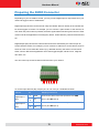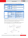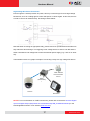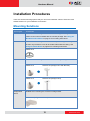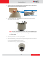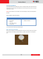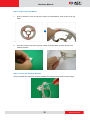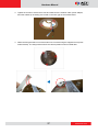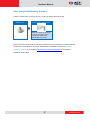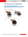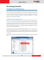
1
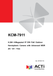
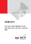
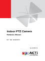
Indoor PTZ Camera Hardware Manual I91, I92, KCM-8111 Ver. 2014/01/14 Hardware Manual Table of Contents Precautions 4 Safety Instructions ........................................................................... 6 Introduction 8 List of Models.................................................................................... 8 Package Contents............................................................................. 9 Physical Description ...................................................................... 10 Connectors View .......................................................................... 10 Internal View ................................................................................ 11 Before Installation 12 Unpacking the Camera ................................................................... 12 Preparing the Power Adapter ........................................................ 13 Preparing the DI/DO Connector ..................................................... 15 Installation Procedures 18 Mounting Solutions ........................................................................ 18 Other Mounting Accessories ........................................................ 20 Mounting on the Ceiling ................................................................. 21 Using the Bundled Surface Mount ............................................... 21 Using the Flush Mount ................................................................. 24 Using the Pendant Mount............................................................. 30 Mounting on Straight Wall ............................................................. 34 Using the L-Type Wall Mount ....................................................... 34 Other Straight Wall Mounting Solutions ....................................... 37 Other Accessories and Adjustments 38 How to Replace the Dome Cover ................................................... 38 How to Reset the Camera............................................................... 39 Resetting KCM-8111 Camera....................................................... 39 2 www.acti.com Hardware Manual Resetting I92 / I93 Camera .......................................................... 39 Accessing Camera 40 Configure the IP Addresses ........................................................... 40 Access the Camera ......................................................................... 44 3 www.acti.com Hardware Manual Precautions Read these instructions You should read all the safety and operating instructions before using this product. Heed all warnings You must adhere to all the warnings on the product and in the instruction manual. Failure to follow the safety instruction given may directly endanger people, cause damage to the system or to other equipment. Servicing Do not attempt to service this video device yourself as opening or removing covers may expose you to dangerous voltage or other hazards. Refer all servicing to qualified service personnel. Trademarks All names used in this manual are probably registered trademarks of respective companies. Liability Every reasonable care has been taken during the writing of this manual. Please inform your local office if you find any inaccuracies or omissions. We cannot be held responsible for any typographical or technical errors and reserve the right to make changes to the product and manuals without prior notice. 4 www.acti.com Hardware Manual Federal Communications Commission Statement This equipment has been tested and found to comply with the limits for a class B digital device, pursuant to Part 15 of the FCC Rules. These limits are designed to provide reasonable protection against harmful interference in a residential installation. This equipment generates, uses, and can radiate radio frequency energy and, if not installed and used in accordance with the instructions, may cause harmful interference to radio communications. However, there is no guarantee that interference will not occur in a particular installation. If this equipment does cause harmful interference to radio or television reception, which can be determined by turning the equipment off and on, the user is encouraged to try to correct the interference by one or more of the following measures: Reorient or relocate the receiving antenna. Increase the separation between the equipment and receiver. Connect the equipment into an outlet on a circuit different from that to which the receiver is connected. Consult the dealer or an experienced radio/TV technician for help. Warning: Changes or modifications to the equipment that are not expressly approved by the responsible party for compliance could void the user’s authority to operate the equipment. European Community Compliance Statement This product has been tested and found to comply with the limits for Class B Information Technology Equipment according to European Standard EN 55022 and EN 55024. In a domestic environment, this product may cause radio interference in which cause the user may be required to take adequate measures. 5 www.acti.com Hardware Manual Safety Instructions Don’t use the power supply with other voltages This device is likely to be damaged or damage other equipments / personnel, if you use a power supply with different voltage than the one included with this device. All warranty of this product will be voided in the situations above. Don’t open the housing of the product Cleaning Disconnect this video product from the power supply before cleaning. Attachments Do not use attachments not recommended by the video product manufacturer as they may cause hazards. Water and Moisture Do not use this video product near water, for example, near a bathtub, washbowl, kitchen sink, or laundry tub, in a wet basement, or near a swimming pool and the like. Don’t use accessories not recommended by the manufacturer Only install this device and the power supply in a dry place protected from weather Servicing Do not attempt to service this video product yourself as opening or removing covers may expose you to dangerous voltage or other hazards. Refer all servicing to qualified service personnel. Damage Requiring service Disconnect this video product from the power supply immediately and refer servicing to qualified service personnel under the following conditions. 1) When the power-supply cord or plug is damaged 2) If liquid has been spilled, or objects have fallen into the video product. 3) If the video product has been directly exposed to rain or water. 6 www.acti.com Hardware Manual 4) If the video product does not operate normally by following the operating Instructions in this manual. Adjust only those controls that are covered by the instruction manual, as an improper adjustment of other controls may result in damage, and will often require extensive work by a qualified technician to restore the video product to its normal operation. Safety Check Upon completion of any service or repairs to this video product, ask the service technician to perform safety checks to determine if the video product is in proper operating condition. 7 www.acti.com Hardware Manual Introduction List of Models This hardware manual contains the following models: 2MP Indoor PTZ with D/N, Advanced WDR, SLLS, 18x Zoom KCM-8111 lens I91 1MP Indoor PTZ with D/N, Extreme WDR, SLLS, 30x Zoom lens I92 2MP Indoor PTZ with D/N, Extreme WDR, SLLS, 30x Zoom lens 8 www.acti.com Hardware Manual Package Contents Camera Power Adapter Universal Plug Converter Surface Mount Mounting Screw Kit Fixing Bracket Drill Template Terminal Block (for Power) Terminal Block (for DIO/DO) Drill Template Quick Installation Guide Warranty Card 9 www.acti.com Hardware Manual Physical Description Connectors View 1) Memory Card Slot Insert a memory card (not included) into the slot for local recording purposes. NOTE: Supports microSDHC and microSDXC cards. 2) Digital Input / Output (DI/DO) This connector connects to digital input or output devices, such as an alarm trigger, panic button, etc. Digital Input (DI) and Digital Output (DO) devices are used in applications like motion detection, event triggering, alarm notifications, etc. Please refer to Preparing the DI/DO Connector on page 15 for information on how to connect DI/DO devices to your camera. 3) Audio IN This jack connects to an audio input device, such as a microphone with built-in amplifier. NOTE: Make sure that the connected audio input device has a built-in amplifier. Connecting an ordinary microphone will dwarf sounds and will result in inaudible recording. 4) Audio OUT This jack connects to an audio output device, such as a speaker. 5) DC 12V Power Input Connect DC power source to the terminal block. The wire with white dashed lines is the live wire, which should connect to the 12V pin. 6) Ethernet Port The Ethernet port connects to a network using a standard Ethernet cable. 10 www.acti.com Hardware Manual Internal View 1) Power Button (in KCM-8111 only) The Power Button is used in case there is a need restart the camera. To restart the camera, press the Power Button using a pointed object, such as a pen. 2) Power LED The Power LED lights red when the camera is powered up. 3) Reset Button The Reset Button is used to restore the factory default settings of the camera, including the administrator’s password. See How to Reset the Camera on page 39. 11 www.acti.com Hardware Manual Before Installation Unpacking the Camera NOTE: To avoid scratches or leaving fingerprints on the dome cover, it is recommended to retain the plastic covering the dome cover until the camera is completely installed. However, the plastic has been removed on the pictures in this documentation to show clarity of the procedures being described. 1. Rotate the dome cover counter-clockwise to remove it. 2. Remove the Styrofoam. 12 www.acti.com Hardware Manual 3. Rotate the dome cover clockwise to attach it. Preparing the Power Adapter In case of using a non-PoE switch or your PoE switch has limited power supply, you can use the bundled power adapter and directly connect the camera to a power outlet. The power adapter must be connected to the supplied terminal block before use. To do this, follow the procedures below: 1. Loosen the screws of the 12V and GND pins of the power terminal block. 13 www.acti.com Hardware Manual 2. Take note that the power adapter cable has two (2) different wires: Connects to GND Pin White stripe: Connects to 12V Pin 3. Connect the wire with the white stripe to the 12V pin and the other to the GND pin. 4. Tighten the screws of the 12V pin and the GND pins to secure the wire connection. 5. Attach one of the bundled adapter plugs suitable in your location. 14 www.acti.com Hardware Manual Preparing the DI/DO Connector Depending on your surveillance needs, you may connect digital input or output devices to your camera to trigger events or notifications. Digital Input (DI) devices can be used to notify the camera about an activity in the camera site. DI can be triggers of events. For example, you can connect a “panic button” to the camera; as such when the panic button is pressed, the alarm signal will be sent through the camera. Other common DI device applications are emergency button, smoke detector, passive infrared sensor, etc. Digital Output (DO) devices are external devices that are activated by the camera upon an event inside the camera. For example, you can connect an “alarm horn” to the camera; as such when an event occurs inside the camera (e.g. detected intruder), the alarm horn will sound. Other common DO device applications are motion-triggered lights, electric fence, magnetic door locks, etc. You can connect up to two DI and two DO devices to your camera. 1 2 3 4 5 6 7 8 To connect input devices (DI), map the pins to one of the pin combinations below: Device Pin Mapping Instructions Digital Input 1 1 GND Connect the wires of the first input device to GND (DI1) 3 DI1 (Pin 1) and DI1 (Pin 3). Digital Input 2 5 GND Connect the wires of the second input device to GND (DI2) 7 DI2 (Pin 5) and DI2 (Pin 7). 15 www.acti.com Hardware Manual To connect output devices (DO), map the pins to one of the pin combinations below: Device Pin Mapping Instructions Digital Output 1 2 12V Connect the wires of the first output device to 12V (DO1) 4 DO1 (Pin 2) and DO1 (Pin 4). Digital Output 2 6 12V Connect the wires of the second output device to 12V (DO2) 8 DO2 (Pin 6) and DO2 (Pin 8). The table below shows the DI/DO connection specifications: Device Connection design DI TTL - compatible logic levels To trigger (low) Logic level 0: 0V ~ 0.4V Normal (high) Logic level 1: 3.1V ~ 30V Voltage Current 10mA ~ 100mA Connection design Transistor (Open Collector) Voltage & Current < 24V DC, < 50mA DO Typical Connection Based on these specifications, if the DI device has a voltage of 0V ~ 30V or the DO device has a voltage of < 24V (< 50mA), then the camera can supply internal power to these devices and there is no need to connect the DI/DO device to an external power source. In this case, wire connection to Pins 1 to 4. Use the GND and DI1 pins to connect a DI device and use the 12V and DO1 pins to connect a DO device. See wiring scheme below: Consequently, to connect a second DI or DO device, wire the connection to Pins 5 to 8. 16 www.acti.com Hardware Manual High Voltage DO Device Connection Even though the camera provides 12V power, this may not be enough for some high voltage DO devices, such as a ceiling light or a motor that opens or closes a gate. In this case, there is a need to connect an external relay. See wiring scheme below: Note that when choosing an appropriate relay, please refer to its specifications and make sure they match the above design. The triggering circuit voltage has to be around 12V DC and the switch-controlled circuit voltage has to match the external power supply (e.g. 110V AC or 220V AC). The illustration below is a graphic example of connecting a relay to a high voltage DO device. 110V-220V AC External Power Source Relay (DO1 Device) ) Camera Illuminator NOTE: For more information on DI/DO connections, please refer to the article All about Digital Input and Digital Output (http://www.acti.com/kb/detail.asp?KB_ID=KB20091230001) in the Knowledge Base section of our website (www.acti.com). 17 www.acti.com Hardware Manual Installation Procedures There are several mounting options that you can use to install the camera. Select the most suitable solution for your installation environment. Mounting Solutions Mount Types Accessories Surface Mount Suitable when mounting the camera on hard or dropped ceilings. The surface mount comes bundled with the camera package. See Using the Bundled Surface Mount on page 21 for mounting instructions. Flush Mount Suitable when mounting the camera discretely above dropped ceilings wherein only the dome cover will be visible underneath the ceiling. See Using the Flush Mount on page 24 for mounting instructions. PMAX-1010 Pendant Mount Straight Wall Suitable when mounting the camera on hard and high ceilings. PMAX-0110 PMAX-0103 (Straight Tube with Bracket) PMAX-0110 PMAX-0102 (Straight Tube) Suitable when mounting the camera on straight walls. Mount PMAX-0311 (L-Type Wall Mount) 18 www.acti.com Hardware Manual Straight Wall PMAX-0110 PMAX-0305 (Heavy Duty Wall Mount) Mount Vertical Pole Mount Horizontal Pole Suitable when mounting the camera on vertical poles. PMAX-0110 PMAX-0305 PMAX-0503 Suitable when mounting the camera on horizontal poles. Mount PMAX-0110 Corner Mount PMAX-0102 PMAX-0503 Suitable when mounting the camera on a corner wall. PMAX-0110 PMAX-0305 19 PMAX-0402 www.acti.com Hardware Manual Other Mounting Accessories Accessories PMAX-0700 (Junction Box) PMAX-0104 (Extension Tubes) NOTE: For more information about the mounting solutions and accessories, please check the Mounting Accessory Selector in our website (http://www.acti.com/mountingselector). Except for the Surface Mount, the above mounting accessories are not included in the package. Contact your sales agents to purchase. 20 www.acti.com Hardware Manual Mounting on the Ceiling There are three mounting solutions that you can do to mount the camera on the ceiling: Surface Mount: To install the camera directly on the ceiling. Accessories come bundled with the camera package. See below for mounting instructions. Flush Mount: To install the camera above the ceiling wherein only the dome cover will be visible from view. See Using the Flush Mount on page 24 for mounting instructions. Pendant Mount: To install the camera on high ceilings and the camera will be lowered by the pendant mount. See Using the Pendant Mount on page 30 for mounting instructions. Using the Bundled Surface Mount The camera package comes with a surface mount kit which allows the camera to be directly installed onto a hard ceiling. 1. Using the mount drill template, mark the screw holes on the ceiling, then drill the holes and insert the supplied plastic plugs. 2. Push at the marked points below to detach the cover ring from the metal plate. 3. Attach the metal plate to the ceiling using the three (3) supplied screws. 21 www.acti.com Hardware Manual 4. Align and attach the fixing bracket to one of the holes on the camera using the supplied screw (holes marked below). The fixing bracket will fix the camera position when mounted later. 5. Align and insert the camera base hooks to the mounting holes of the metal plate. 6. Slide the camera clockwise to secure the hooks to the mount. 22 www.acti.com Hardware Manual 7. Tighten the screw on the fixing bracket to fix the camera position. This is to avoid accidental camera movement as the camera performs PTZ functions. 8. Connect the network cable, power adapter and any other cable connections (such as DI/DO, audio in, etc.) to the camera. NOTE: The cables may be routed along the ceiling if the camera is installed on a hard ceiling. Or, the cables may pass through a hole on the ceiling if the camera is installed on a dropped ceiling. 9. Remove the pre-cut tab on the cover ring using pliers. 10. Note that the cables will pass through the cut, align the metal plate hooks onto the holes of the cover ring and then push to secure it in place. Final installation would look similar to the picture below. 23 www.acti.com Hardware Manual Using the Flush Mount Use the Flush Mount when installing the camera on a dropped ceiling; there is space above the ceiling where the camera body can be hidden from view and only the dome cover can be seen underneath the ceiling. NOTE: The Flush Mount is not included in the camera package. Contact your sales agents to purchase. Before installation, prepare the following: Flush Mount Kit Other Tools (not supplied) Flush Mount Jig saw Drill template Phillips screwdriver Screw (1) Foam rubber pads (3) Fixing bracket To mount the camera, follow the procedures below: Step 1: Drill a Hole on the Ceiling Drill a 184-mm diameter hole on the ceiling where you want to mount the camera, then route the network cable, power adapter, and other cables (e.g. DI/DO, audio cables, etc.) through the hole. 24 www.acti.com Hardware Manual Step 2: Prepare the Flush Mount 1. Push to detach the cover ring from the mount as marked below. Then set the cover ring aside. 2. Peel off the lining of the three (3) foam rubber pads and attach a rubber pad to each retaining bracket. Step 3: Loosen the Retaining Brackets Using a screwdriver, loosen the retaining brackets according to the thickness of the ceiling. 25 www.acti.com Hardware Manual Step 4: Install the Mount 1. Insert the metal bracket through the hole until the ring edge is flat on the ceiling. 2. Position the retaining brackets to hold the mount on the ceiling. NOTE: The following illustration shows how the flush mount will look like when viewed from inside the ceiling. In case you cannot access inside the ceiling, use your fingers to position the retaining brackets through the hole. 26 www.acti.com Hardware Manual 3. Tighten the screws to secure the mount and make sure the network cable, power adapter, and other cables (if necessary) are routed on the outer gap of the metal bracket. 4. Attach the fixing bracket to one of the holes on the camera using the supplied screw (holes marked below). The fixing bracket will fix the camera position when mounted later. 27 www.acti.com Hardware Manual Step 5: Connect the Cables and Optional Accessories Insert a memory card into the camera card slot (if necessary). Connect the network cable, power adapter, and other cables, such as DI/DO, etc. (if any) to the camera. Step 6: Install the Camera 1. Align the camera base hooks to the holes on the bracket and then insert the camera through the bracket. NOTE: Take note that the network cable must be bent to insert the camera into the mount. If the network cable you are using is not flexible or too rough to be bent, it is recommended to use the bundled network extension cable (included in the camera package). The bundled network extension cable is flexible enough to be bent and makes it easy to insert the camera through the mount. Or, if you can access the inside of the ceiling, you may mount the camera first and then connect the cables. 28 www.acti.com Hardware Manual 2. Slide the camera clockwise to secure the hooks to the mount. Notice that the fixing bracket screw becomes aligned with the hole on the metal bracket 3. Tighten the screw on the fixing bracket to fix the camera position. This is to avoid accidental camera movement as the camera performs PTZ functions. Step 7: Attach the Cover Ring 1. Align the metal latches and the latches on the cover ring. 2. Push to firmly secure the cover ring latches. 29 www.acti.com Hardware Manual Using the Pendant Mount In case of high ceilings, the camera can be lowered by pendant mount. NOTE: The Pendant Mount is not included in the camera package. Contact your sales agents to purchase. Prepare the following: Pendant Mount Kits (PMAX-0110 and either PMAX-0103 or PMAX-0102) PMAX-0110 PMAX-0102 (Straight Tube without Bracket) PMAX-0103 (Straight Tube with Bracket) or Use this configuration if the cable cannot directly enter the ceiling and must go along the ceiling. Use this configuration if the cable can directly enter the ceiling. Mounting Screws (included in the mount kit package) Network Extension Cable (included in the PMAX-0110 kit) Screwdriver (not included) Step 1: Install the Straight Tube 1. Use the drill template (included in the straight tube package) to mark and drill the mounting holes on the ceiling. 2. Insert the power adapter, network cable, and other necessary cables (if any) to pass through the straight tube. Note that you must insert the power adapter cable first to fit the tube. NOTE: If using a straight tube without bracket, route the cables to pass through the hole on the ceiling. The following illustrations show the installation using a straight tube with bracket. 30 www.acti.com Hardware Manual 3. Install the straight tube on the ceiling. NOTE: If the straight tube is not long enough, you may use one or more extension tubes (purchased separately). Step 2: Install the Mount Kit (PMAX-0110) 1. Insert the cables from the tube into the mount kit and route them to pass through the outer bracket. 2. Align the slot of the mount kit to the tab inside the straight tube and install the mount kit. 31 www.acti.com Hardware Manual 3. Twist the mount kit to align the screw holes and attach the two (2) mounting screws (included in the mount kit package). Step 3: Install the Camera 1. Connect the network cable to the Ethernet port of the camera. If necessary, connect the other cables (such as power adapter, DI/DO, etc.) to the corresponding connectors. NOTE: Try to push the network cable further into the mount. T I P: If the network cable texture is rough and not easily bent, use the bundled network extension cable (included in the mount kit package) to easily route the cables because of its flexibility. 2. Align and insert the camera base hooks to the mounting holes. 32 www.acti.com Hardware Manual 3. Slide the camera counter-clockwise to secure the hooks to the mount. 4. On the top of the mount kit, attach three (3) screws (included in the mount kit package) to secure the camera to the mount. The final installation would look similar to the one below: 33 www.acti.com Hardware Manual Mounting on Straight Wall There are four (4) mounting solutions that you can do to mount the camera on the straight wall. The L-Type Wall Mount is used to install the camera facing down as if it is installed on a ceiling (see below for mounting instructions). Other straight wall mounting solutions, such as the Heavy Duty Wall Mount allow the camera to be installed further away from the wall. Cables may be routed through the wall or along the wall. Select the solution that is most applicable to your installation requirements. Using the L-Type Wall Mount To install the camera on a straight wall, use the L-Type Wall Mount. The camera will be facing down as if installed on a ceiling. NOTE: The L-Type Wall Mount is not included in the camera package. Contact your sales agents to purchase. Before installation, prepare the following: L-Type Wall Mount Package L-Type Wall Mount Drill template Screws (3) Other Tools (not supplied) Phillips screwdriver Step 1: Install the L-Type Wall Mount Use the drill template (included in the L-type wall mount package) to mark and drill the mounting holes on the wall. Route the cable(s). 2a. If the cable(s) will pass through the wall, insert the cable(s) through the cable hole as marked below (A). A 2b. If the cable will go along the wall, remove the pre-cut tab on the L-type wall mount 34 www.acti.com Hardware Manual using pliers. Then route the cable through the cable holes (A to B) as marked below. B A With the cable(s) dangling, attach three (3) screws (included in the camera package) to install the L-type wall mount onto the wall. Step 2: Install the Camera 1. Connect the network cable to the Ethernet port of the camera. If necessary, connect the other cables (such as power adapter, DI/DO, etc.) to the corresponding connectors. 35 www.acti.com Hardware Manual 2. Align and insert the camera base hooks to the mounting holes. 3. Slide the camera clockwise to secure the hooks to the mount. 4. Attach three (3) screws (included in the L-type wall mount package) to secure the camera to the mount. 36 www.acti.com Hardware Manual Other Straight Wall Mounting Solutions Another straight wall mounting solution include the Heavy Duty Mount Kit: PMAX-0110 PMAX-0305 (Heavy Duty Wall Mount) Cable can either go through a hole in the wall or pass through the cable hole underneath the mount. NOTE: The above mentioned mounting accessories are not included in the camera package. Contact your sales agents to purchase. Download the Installation Guide from Mounting Accessory Selector in our website (http://www.acti.com/mountingselector) for detailed installation instructions. 37 www.acti.com Hardware Manual Other Accessories and Adjustments How to Replace the Dome Cover Depending on your surveillance needs, you may want to replace the bundled dome cover with a smoke dome cover available for purchase. To replace the dome cover, do the following: 1. Rotate the dome cover counter-clockwise to remove it. 2. Rotate the replacement dome cover clockwise to attach it. 38 www.acti.com Hardware Manual How to Reset the Camera A reset may be necessary if the following instances happen: The administrator’s password has been forgotten and therefore the camera cannot be accessed. In case of IP address, mask, or allow/deny filter related issues, resulting with inability to modify these settings. In case of connectivity issues or abnormal video quality. Resetting KCM-8111 Camera 1. Disconnect the power supply (e.g. disconnect the power adapter or the high PoE injector). 2. Press and continue to hold the reset button (using a sharp object, such as a pen). 3. Connect the power supply while keeping the reset button pressed. 4. Wait for 45 seconds and release the reset button. Resetting I92 / I93 Camera With the camera powered on, press and hold the reset button for at least 5 seconds or until the Power LED goes off (using a sharp object, such as a pen). 39 www.acti.com Hardware Manual Accessing Camera Configure the IP Addresses In order to be able to communicate with the camera from your PC, both the camera and the PC have to be within the same network segment. In most cases, it means that they both should have very similar IP addresses, where only the last number of the IP address is different from each other. There are 2 different approaches to IP Address management in Local Area Networks – by DHCP Server or Manually. Using DHCP server to assign IP addresses If you have connected the computer and the camera into the network that has a DHCP server running, then you do not need to configure the IP addresses at all – both the camera and the PC would request a unique IP address from the DHCP server automatically. In such case, the camera will immediately be ready for the access from the PC. The user, however, might not know the IP address of the camera yet. It is necessary to know the IP address of the camera in order to access it using a Web browser. The quickest way to discover the cameras in the network is to use the simplest network search, built in the Windows system – just by pressing the “Network” icon, all the cameras of the local area network will be discovered by Windows, thanks to the UPnP function support of our cameras. In the example below, the camera that has just been connected to the network is successfully found. 40 www.acti.com Hardware Manual When the left mouse is clicked on the camera model name, the default browser of the PC is automatically launched and the IP address of the target camera is already filled in the address bar of the browser. If you work with our cameras regularly, then there is even a better way to discover the cameras in the network – by using IP Utility. The IP Utility is a light software tool that can not only discover the cameras, but also list lots of valuable information, such as IP and MAC addresses, serial numbers, firmware versions, etc, and allows quick configuration of multiple devices at the same time. The IP Utility can be downloaded for free from http://www.acti.com/IP_Utility When you launch IP Utility, the list of connected cameras in the network will be shown. See sample illustration below: You can quickly notice the KCM-8211 model in the list. Click on the IP address to automatically launch the default browser of the PC with the IP address of the target camera already filled in the address bar of the browser. 41 www.acti.com Hardware Manual Use the default IP address of the camera If there is no DHCP server in the given network, the user may have to manually assign the IP addresses to both the PC and the camera to make sure they are in the same network segment. When the camera is plugged into the network and it does not detect any DHCP services, it will automatically assign itself a default IP: 192.168.0.100 Whereas the default port number would be 80. In order to access that camera, the IP address of the PC has to be configured to match the network segment of the camera. Manually adjust the IP address of the PC In the following example, based on Windows 7, we will configure the IP address to 192.168.0.99 and set Subnet Mask to 255.255.255.0 by using the steps below: 1 3 2 4 42 www.acti.com Hardware Manual Manually adjust the IP addresses of multiple cameras If there are more than one camera to be used in the same local area network and there is no DHCP server to assign unique IP addresses to each of them, all of the cameras would then have the initial IP address of 192.168.0.100, which is not a proper situation for network devices – all the IP addresses have to be different from each other. The easiest way to assign cameras the IP addresses is by using IP Utility: With the procedure shown above, all the cameras will have unique IP addresses, starting from 192.168.0.101. In case there are 20 cameras selected, the last one of the cameras would have the IP 192.168.0.120. Later, by pressing the “Refresh” button of the IP Utility, you will be able to see the list of cameras with their new IP addresses. Please note that it is also possible to change the IP addresses manually by using the Web browser. In such case, please plug in only one camera at a time, and change its IP address by using the Web browser before plugging in the next one. This way, the Web browser will not be confused about two devices having the same IP address at the same time. 43 www.acti.com Hardware Manual Access the Camera Now that the camera and the PC both have their unique IP addresses and are under the same network segment, you can use Microsoft Internet Explorer on the PC to access the camera. You can use any of the browsers to access I91 or I92 cameras, however, the full functionality is provided only for Microsoft Internet Explorer. NOTE: Only Microsoft Internet Explorer is supported by KCM-8111 at the time of writing this documentation. Please refer to our website (www.acti.com) for future upgrades. The browser functionality comparison: Internet Explorer Other browsers (For I91 / I92 only) Live Video Yes Yes* Live Video Area Resizable Yes No PTZ Control Yes Yes Capture the snapshot Yes Yes Yes No Yes Yes Functionality Video overlay based configuration (Motion Detection regions, Privacy Mask regions) All the other configurations * QuickTime (http://www.apple.com/quicktime/download/) has to be installed in the PC first before using any non-Internet Explorer browsers to be able to get live video feed from the camera with those browsers. It is a free and open source cross-platform multimedia player. Disclaimer Notice: The camera manufacturer does not guarantee the compatibility of its cameras with QuickTime – since it is a third party software, the third party has the right to modify their utility any time which might affect the compatibility. In such cases, please use Internet Explorer browser instead. When using Internet Explorer browser, the ActiveX control for video stream management will be downloaded from the camera directly – the user just has to accept the use of such control when prompted so. No other third party utilities are required to be installed in such case. The examples in this manual are based on Internet Explorer browser in order to cover all functions of the camera. 44 www.acti.com Hardware Manual Assuming that the camera’s IP address is 192.168.0.100, you can access it by opening the Web browser and typing the following address into Web browser’s address bar: http://192.168.0.100 Upon successful connection to the camera, the user interface called Web Configurator would appear together with the login page. The HTTP port number was not added behind the IP address since the default HTTP port of the camera is 80, which can be omitted from the address for convenience. Before logging in, you need to know the factory default Account and Password of the camera. Account: Admin Password: 123456 For further operations, please refer to the Firmware User’s Manual. 45 www.acti.com