1
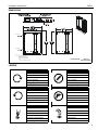
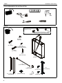
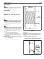
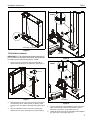
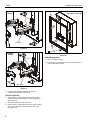
INSTALLATION INSTRUCTIONS
WITH TS118
WITH TS218
THINSTALL™ IN-WALL ENCLOSURE
Spanish Product Description
German Product Description
Portuguese Product Description
Italian Product Description
Dutch Product Description
French Product Description
TA502
TA502
Installation Instructions
DISCLAIMER
Milestone AV Technologies, and its affiliated corporations and
subsidiaries (collectively, "Milestone"), intend to make this
manual accurate and complete. However, Milestone makes no
claim that the information contained herein covers all details,
conditions or variations, nor does it provide for every possible
contingency in connection with the installation or use of this
product. The information contained in this document is subject
to change without notice or obligation of any kind. Milestone
makes no representation of warranty, expressed or implied,
regarding the information contained herein. Milestone assumes
no responsibility for accuracy, completeness or sufficiency of
the information contained in this document.
Chief® is a trademark of Milestone AV Technologies.
All rights reserved.
IMPORTANT SAFETY INSTRUCTIONS!
WARNING: Use this mounting system only for its intended
use as described in these instructions. Do not use
attachments not recommended by the manufacturer.
WARNING: Never operate this mounting system if it is
damaged. Return the mounting system to a service center for
examination and repair.
WARNING: Do not use this product outdoors.
NOTES:
•
SUITABLE FOR USE IN OTHER
ENVIRONMENTAL AIR SPACE IN
ACCORDANCE WITH SECTION 300.22, (C)
OF THE NATIONAL ELECTRICAL CODE.
•
The equipment shall be installed and
assembled by qualified service personnel.
•
The maximum specified ambient temperature
of the cabinet system is 40° - 120°F (4° - 49°).
•
Minimum spacings between the accessories
and components and the housing for
Information Technology Communication
Equipment shall be maintained for safe
operation of the equipment when installed in
accordance with the National Electric Code,
ANSI/NFPA 70-1999. Refer to communication
equipment manufacturer’s specifications for
minimum spacings.
•
This Cabinet System is for use with Listed wall
mounts. Refer to the individual mount’s
installation instructions for compatibility.
WARNING: A WARNING alerts you to the possibility of
serious injury or death if you do not follow the instructions.
CAUTION: A CAUTION alerts you to the possibility of
damage or destruction of equipment if you do not follow the
corresponding instructions.
WARNING: Failure to read, thoroughly understand, and
follow all instructions can result in serious personal injury,
damage to equipment, or voiding of factory warranty! It is the
installer’s responsibility to make sure all components are
properly assembled and installed using the instructions
provided.
--SAVE THESE INSTRUCTIONS-WARNING: Failure to provide adequate structural strength
for this component can result in serious personal injury or
damage to equipment! It is the installer’s responsibility to
make sure the structure to which this component is attached
can support five times the combined weight of all equipment.
Reinforce the structure as required before installing the
component. The wall to which the mount is being attached
may have a maximum drywall thickness of 5/8" (1.6cm).
WARNING: Exceeding the weight capacity can result in
serious personal injury or damage to equipment! It is the
installer’s responsibility to make sure the structure to which
this accessory is attached can support the combined weight
of the box and all equipment not to exceed 75 lbs (34.0 kg).
The combined weight of all components attached to the
TS118SU mount cannot exceed 35 lbs (15.9 kg). The
combined weight of all components attached to the TS218SU
mount cannot exceed 75 lbs (34.0 kg).
2
Installation Instructions
TA502
DIMENSIONS
GROUNDING
18.85
478.8
GROUNDING
TRIM NOT SHOWN
NOTES:
ELECTRICAL KNOCK OUTS:
1.
•
SINGLE GANG RACO 590.
STEEL CITY CY 1/2, OR
SIMILAR STYLE ELECTRICAL
BOX.
•
1" AND 2" TRADE PIPE CONDUIT.
2.
PRODUCT WORKS WITH TS118 AND TS218.
(USE THESE DIMENSIONS FOR CUTOUT)
DIMENSIONS:
INCHES
[MILLIMETERS]
LEGEND
Tighten Fastener
Pencil Mark
Apretar elemento de fijación
Marcar con lápiz
Befestigungsteil festziehen
Stiftmarkierung
Apertar fixador
Marcar com lápis
Serrare il fissaggio
Segno a matita
Bevestiging vastdraaien
Potloodmerkteken
Serrez les fixations
Marquage au crayon
Loosen Fastener
Drill Hole
Aflojar elemento de fijación
Perforar
Befestigungsteil lösen
Bohrloch
Desapertar fixador
Fazer furo
Allentare il fissaggio
Praticare un foro
Bevestiging losdraaien
Gat boren
Desserrez les fixations
Percez un trou
Phillips Screwdriver
Hex-Head Wrench
Destornillador Phillips
Llave de cabeza hexagonal
Kreuzschlitzschraubendreher
Sechskantschlüssel
Chave de fendas Phillips
Chave de cabeça sextavada
Cacciavite a stella
Chiave esagonale
Kruiskopschroevendraaier
Zeskantsleutel
Tournevis à pointe cruciforme
Clé à tête hexagonale
3
TA502
Installation Instructions
TOOLS REQUIRED FOR INSTALLATION
3/16"
PARTS
Grounding screw and washer
installed at factory
Earthing symbol IEC 60417 No. 5019
affixed adjacent to grounding terminal.
B (4)
[Mounting
spacers]
C (4)
M7 x 40mm
E (6)
08 x 1/2"
[Extras if needed for
installing electrical box]
D (4)
M7 x 50mm
F (1)
M4
[Allen driver bit]
A (1)
[TA502]
J (12)
[5-1/2" cable tie]
K (16)
[Tape squares]
G (4 - 2 long, 2 short)
[Trim pieces]
4
H (4)
[Cable tie mounts]
L (4)
[9/16"]
M (4)
5/16-18 X 1/2"
N (3)
1/4-20 x 1/2"
P (1)
[attach bracket]
Installation Instructions
TA502
INSTALLATION
TA502
CUTOUT AREA
WARNING: IMPROPER INSTALLATION CAN RESULT
DEATH OR SERIOUS PERSONAL INJURY! This accessory
should be installed by qualified personnel.
Site Preparation
Locate and Prepare Mounting Site
1.
Identify a suitable wall location for the in-wall enclosure.
IMPORTANT ! : The TA502 is designed for in-wall
installation between two wood studs, 16" on center.
Inadequate space will remain on each side between
studs for electrical wires/cables, plumbing, ductwork, or
insulation. Locate accordingly!
17.2”
(436.9 mm)
WARNING: ELECTRICAL SHOCK HAZARD! CUTTING
OR DRILLING INTO ELECTRICAL WIRES OR CABLES
CAN CAUSE DEATH OR SERIOUS PERSONAL INJURY!
ALWAYS make certain area behind mounting surfaces is free
of electrical wires and cables before cutting, drilling, or
installing fasteners.
WARNING: EXPLOSION AND FIRE HAZARD! CUTTING
OR DRILLING INTO GAS PLUMBING CAN CAUSE DEATH
OR SERIOUS PERSONAL INJURY! ALWAYS make certain
area behind mounting surfaces is free of gas, water, waste, or
any other plumbing before cutting, drilling, or installing
fasteners.
14-1/2”
(368 mm)
Figure 1
2.
Using a stud sensor, locate and mark studs.
Frame Housing
3.
Center and level housing between marked studs.
4.
Using housing as a template, draw pencil line completely
around housing.
IMPORTANT ! : Consult a qualified building contractor to
install housing framing and follow all applicable building
codes!
NOTE: Housing is designed to fit between and directly against
two adjacent wall studs.
5.
Cut drywall on outside edge of line and remove.
1.
Cut four 8" long blocks for support framing.
2.
Using three #10 x 2-1/2" countersunk wood screws (not
provided), attach support framing to the studs (See Figure
2)
support
framing
horizontal framing
Top View
Wood
Screws
(5 places)
(Typical for each
support framing block)
Figure 2
5
TA502
Installation Instructions
NOTE: Ensure screws are far enough from block end to
prevent interference with framing screws installed in InWall Enclosure Installation section.
3.
If necessary, cut rectangular hole in horizontal framing to
accommodate the PAC-GB1 Listed electrical box accessory
(not included).
4.
Attach horizontal framing to each support block with two
#10 x 2-1/2" countersunk wood screws (not provided).
(See Figure 2)
7
(D) x 4
In-Wall Enclosure Installation
1.
Install PAC-GB1 Listed electrical box accessory (not
included) into the TA502 (A) following instructions included
with the PAC-GB1.
2.
Connect electrical wiring.
3.
Route audio/visual cables into housing.
4.
Center TA502 (A) in opening and insert into opening.
5.
Align front of box with front face of wall. (See Figure 3)
(B) x 4
Figure 4
(A)
8.
Drill four 3/16" diameter pilot holes in horizontal framing at
mounting holes.
9.
Attach the TA502 (A) to horizontal framing using four M7 x
40mm Allen head connector screws (C) using an M4 Allen
head drill bit (F). (See Figure 5)
Side Mounting
Holes
9
(C) x 4
Figure 3
WARNING: ELECTRICAL SHOCK HAZARD! CUTTING
OR DRILLING INTO ELECTRICAL WIRES OR
CABLES CAN CAUSE DEATH OR SERIOUS
PERSONAL INJURY! ALWAYS make certain area behind
mounting surfaces is free of electrical wires and cables
before cutting, drilling, or installing fasteners.
6.
Drill four 3/16" diameter pilot holes in studs at side mounting
holes. (See Figure 3)
7.
Attach the TA502 (A) using four M7 x 50mm Allen head
connector screws (D) and four spacers (B) into pilot holes
using an M4 Allen head drill bit (F). (See Figure 4)
NOTE: The TA502 has 1/2" total clearance between the two
studs. The spacers allow side to side adjustment.
6
Figure 5
DANGER: IMPROPER WIRING CAN LEAD TO DEATH
OR SEVERE PERSONAL INJURY! Grounding must be
installed by qualified personnel using a UL Recognized No.
12AWG grounding wire connected to grounding lug on
mount.
Installation Instructions
TA502
(TS118SU
install) 1/4"
3
2
Grounding Lug Locations
(N)
Figure 6
TS118/218SU Installation
TS118SU
IMPORTANT ! : The TA502 was designed specifically for
the TS118SU and TS218SU wall mounts. Do not attempt
to install any other wall mounts with the TA502!
1.
Use four 5/16-18 x 1/2" button head cap screws (M) to
attach attach bracket (P) to the TA502 (A). (See Figure 7)
1
Figure 8
(TS218SU
install)
1/4"
(M) x 4
3
(P)
2
Figure 7
2.
3.
Partially install 1/4-20 x 1/2" button head cap screw (N) into
corresponding hole on attach bracket (P), leaving screw
hanging out 1/4" from bracket. (See Figure 8) or (See Figure
9)
(N)
TS218SU
Figure 9
4.
Use one (TS118SU) or two (TS218SU) 1/4-20 x 1/2" button
head cap screws (N) to attach TS118/218SU to attach
bracket (P). (See Figure 10) and (See Figure 11)
5.
Tighten all screws to secure TS118/218SU to attach bracket
(P). (See Figure 10) and (See Figure 11)
Hang TS118/218SU mount onto screw by latching keyshaped hole over screw. (See Figure 8) or (See Figure 9)
7
TA502
Installation Instructions
(G) x 4
(TS118SU
install)
(TS118/218TU mount
not shown for clarity)
5
3
TS118SU
(N)
4
Figure 10
1 (K) x 16
(TS218SU
install)
5
Figure 12
Cable Management
4
(N) x 2
TS218SU
Figure 11
6.
Complete TS118/218SU installation according to
corresponding installation instructions.
Trim Kit (Optional)
1.
Remove paper covering adhesive and affix three tape
squares (K) to inside lower flange of each trim piece (G).
(See Figure 12)
2.
Orient trim pieces (G). (See Figure 12)
3.
Remove paper covering adhesive back from tape squares
(K) on trim and press trim (G) against inner wall of box.
(See Figure 12)
8
1.
Attach all cables to display.
2.
If necessary, use cable tie mounts (H) and cable ties (J) to
secure cables within TA502.
Installation Instructions
TA502
9
TA502
10
Installation Instructions
Installation Instructions
TA502
11
TA502
Installation Instructions
USA/International
Chief Manufacturing, a products division
of Milestone AV Technologies
Europe
Asia Pacific
8800-002233 Rev00
2012 Milestone AV Technologies,
a Duchossois Group Company
www.chiefmfg.com
12/12
A
P
F
A
P
F
A
6436 City West Parkway, Eden Prairie, MN 55344
800.582.6480 / 952.225.6000
877.894.6918 / 952.894.6918
Franklinstraat 14, 6003 DK Weert, Netherlands
+31 (0) 495 580 852
+31 (0) 495 580 845
Office No. 1 on 12/F, Shatin Galleria
18-24 Shan Mei Street
Fotan, Shatin, Hong Kong
P 852 2145 4099
F 852 2145 4477