1
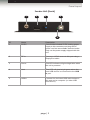
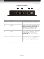
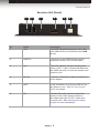
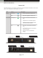
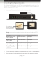
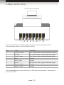
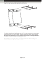
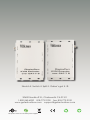
Audio
DisplayPort
KVM
3GSDI Embedder
Extender over CAT-7
GTB-DPKVM-3CAT7
GTB-DPKVM-3CAT7-BLK
User Manual
Release A7
DisplayPort KVM Extender over CAT-7
Important Safety Instructions
GENERAL SAFETY INFORMATION
1.
Read these instructions.
2.
Keep these instructions.
3.
Heed all warnings.
4.
Follow all instructions.
5.
Do not use this product near water.
6.
Clean only with a dry cloth.
7.
Do not block any ventilation openings. Install in accordance with the manufacturer’s
instructions.
8.
Do not install or place this product near any heat sources such as radiators, heat
registers, stoves, or other apparatus (including amplifiers) that produce heat.
9.
Do not defeat the safety purpose of the polarized or grounding-type plug. A polarized
plug has two blades with one wider than the other. A grounding type plug has two
blades and a third grounding prong. The wide blade or the third prong are provided for
your safety. If the provided plug does not fit into your outlet, consult an electrician for
replacement of the obsolete outlet.
10. Protect the power cord from being walked on or pinched particularly at plugs,
convenience receptacles, and the point where they exit from the apparatus.
11. Only use attachments/accessories specified by the manufacturer.
12. To reduce the risk of electric shock and/or damage to this product, never handle or
touch this unit or power cord if your hands are wet or damp. Do not expose this
product to rain or moisture.
13. Unplug this apparatus during lightning storms or when unused for long periods of time.
14. Refer all servicing to qualified service personnel. Servicing is required when the
apparatus has been damaged in any way, such as power-supply cord or plug is
damaged, liquid has been spilled or objects have fallen into the apparatus,
the apparatus has been exposed to rain or moisture, does not operate normally,
or has been dropped.
15. Batteries that may be included with this product and/or accessories should never be
exposed to open flame or excessive heat. Always dispose of used batteries
according to the instructions.
ii
DisplayPort KVM Extender over CAT-7
Warranty Information
Gefen warrants the equipment it manufactures to be free from defects in material and
workmanship.
If equipment fails because of such defects and Gefen is notified within two (2) years from
the date of shipment, Gefen will, at its option, repair or replace the equipment, provided
that the equipment has not been subjected to mechanical, electrical, or other abuse or
modifications. Equipment that fails under conditions other than those covered will be
repaired at the current price of parts and labor in effect at the time of repair. Such repairs
are warranted for ninety (90) days from the day of reshipment to the Buyer.
This warranty is in lieu of all other warranties expressed or implied, including without
limitation, any implied warranty or merchantability or fitness for any particular purpose, all of
which are expressly disclaimed.
1.
Proof of sale may be required in order to claim warranty.
2.
Customers outside the US are responsible for shipping charges to and from Gefen.
3.
Copper cables are limited to a 30 day warranty and cables must be in their original
condition.
The information in this manual has been carefully checked and is believed to be accurate.
However, Gefen assumes no responsibility for any inaccuracies that may be contained
in this manual. In no event will Gefen be liable for direct, indirect, special, incidental, or
consequential damages resulting from any defect or omission in this manual, even if
advised of the possibility of such damages. The technical information contained herein
regarding the features and specifications is subject to change without notice.
For the latest warranty coverage information, refer to the Warranty and Return Policy under
the Support section of the Gefen Web site at www.gefen.com.
PRODUCT REGISTRATION
Please register your product online by visiting the Register Product page under the
Support section of the Gefen Web site.
iii
DisplayPort KVM Extender over CAT-7
Contacting Gefen Technical Support
Gefen, LLC
c/o Customer Service
20600 Nordhoff St.
Chatsworth, CA 91311
Telephone:
(818) 772-9100
(800) 545-6900
Fax:
(818) 772-9120
Email:
[email protected]
Visit us on the Web:
www.gefentoolbox.com
Technical Support Hours:
8:00 AM to 5:00 PM Monday - Friday, Pacific Time
DisplayPort KVM Extender over CAT-7 is a trademark of Gefen, LLC.
Important Notice
Gefen, LLC reserves the right to make changes in the hardware, packaging, and any
accompanying documentation without prior written notice.
© 2013 Gefen, LLC. All Rights Reserved.
All trademarks are the property of their respective owners.
iv
DisplayPort KVM Extender over CAT-7
Operating Notes
•
CAT-7 cables should not exceed 100 feet (30 meters).
•
Resolutions up to 1920 x 1200 (WUXGA) or 1080p Full HD plus USB are supported
when using two CAT-7 cables. Three CAT-7 cables must be used to support
2560 x 1600 (WQXGA) plus USB. See Connecting the DisplayPort KVM Extender
over CAT-7 for details.
•
The DisplayPort KVM Extender over CAT-7 only supports 8-bit color.
•
This product extends DisplayPort video only. It does not support audio.
v
DisplayPort KVM Extender over CAT-7
Features and Packing List
Features
•
Extends DisplayPort and USB up to 100 feet (30 meters)
•
Supports resolutions up to 2560 x 1600 and USB over three CAT-7 cables,
and up to 1920 x 1200 or 1080p Full HD at 120Hz and USB over two CAT-7 cables
•
HDCP compliant
•
Supports DisplayPort 1.1a
•
Supports USB 2.0 at 480 Mbps
•
Backward-compatible with USB 1.1
•
16-position EQ rotary switch to compensate for cable skew
•
HPD Auto-Calibration button
•
Pre-emphasis switch
•
Drive level switch
•
Boost level switches
•
Power On indicator
•
Independent Video and USB Link indicators
•
Locking power supplies
•
Surface-mountable
•
Available in Black and White
1080P
Packing List
The DisplayPort KVM Extender over CAT-7 ships with the items listed below. If any of these
items are not present in the box when you first open it, immediately contact your dealer or
Gefen.
•
•
•
•
•
•
1 x DisplayPort KVM Extender over CAT-7 (Sender unit)
1 x DisplayPort KVM Extender over CAT-7 (Receiver unit)
1 x 6 ft. DisplayPort cable (M-M)
1 x 6 ft. USB cable (A-B)
2 x 5V DC power supplies
1 x Quick-Start Guide
vi
DisplayPort
KVM
Extender over CAT-7
3GSDI Audio
Embedder
Table of Contents
01
Getting Started
Panel Layout.......................................................................................................... 2
Sender Unit (Front)........................................................................................ 2
Sender Unit (Back)......................................................................................... 3
Receiver Unit (Front)...................................................................................... 4
Receiver Unit (Back)...................................................................................... 5
Installation.............................................................................................................. 6
Connecting the DisplayPort KVM Extender over CAT-7������������������������������� 6
Sample Wiring Diagram................................................................................. 7
02
Operating the DisplayPort KVM Extender
over CAT-7
LED Indicators...................................................................................................... 10
Sender Unit.................................................................................................. 10
Receiver Unit................................................................................................ 11
DIP Switch Configuration..................................................................................... 12
Hot-Plug Detect (HPD)......................................................................................... 13
Adjusting the Signal Quality................................................................................. 14
03Appendix
Cable Termination................................................................................................ 18
Surface-Mounting Instructions............................................................................. 19
Specifications....................................................................................................... 20
vii
DisplayPort KVM
Extender over CAT-7
01 Getting Started
Panel Layout.......................................................................................................... 2
Sender Unit (Front)........................................................................................ 2
Sender Unit (Back)......................................................................................... 3
Receiver Unit (Front)...................................................................................... 4
Receiver Unit (Back)...................................................................................... 5
Installation.............................................................................................................. 6
Connecting the DisplayPort KVM Extender over CAT-7������������������������������� 6
Sample Wiring Diagram................................................................................. 7
Getting Started
Panel Layout
Sender Unit (Front)
1
2
3
ID
Name
Description
1
USB Link
Connect a CAT-7 cable between this jack
and the USB Link jack on the Receiver
unit. This RJ-45 jack must be used when
extending USB.
2
Link 1
Connect a CAT-7 cable between this RJ-45
jack and the Link 1 jack on the Receiver unit.
3
Link 2
Connect a CAT-7 cable between this
RJ-45 jack and the Link 2 jack on the
Receiver unit. Both Link 1 and Link 2 jacks
(two CAT-7 cables) must be used when
extending video resolutions up to
2560 x 1600.
page | 2
Getting Started
Panel Layout
Sender Unit (Back)
1
2
3
5
4
ID
Name
Description
1
5V DC
Connect the included 5V DC locking power
supply to this connector and plug the AC
power cord into an available electrical outlet.
Only use the power supply shipped with this
unit.
2
DP In
Connect a Hi-Def source to this port using a
DisplayPort cable.
3
Power
This LED indicator will glow bright blue when
the unit is powered.
4
Host
This LED will glow bright green when the
host USB device is connected to the USB
In port.
5
USB In
Connect the included USB cable between
this port and a computer (or other USB
host device).
page | 3
Getting Started
Panel Layout
Receiver Unit (Front)
1
2
3
4
ID
Name
Description
1
Link 1
Connect a CAT-7 cable between this RJ-45
jack and the Link 1 jack on the Sender unit.
2
Link 2
Connect a CAT-7 cable between this RJ-45
jack and the Link 2 jack on the Sender unit.
Both Link 1 and Link 2 jacks (two CAT-7
cables) must be used when extending
video resolutions up to 2560 x 1600.
3
Link 2
Connect a CAT-7 cable between this jack
and the USB Link jack on the Sender
unit. This RJ-45 jack must be used when
extending USB.
4
5V DC
Connect the included 5V DC locking power
supply to this connector and plug the AC
power cord into an available electrical outlet.
Only use the power supply shipped with this
unit.
page | 4
Getting Started
Panel Layout
Receiver Unit (Back)
1
2
3
4
5
6
ID
Name
Description
1
Host
This LED will glow bright green when the
host USB device is connected to the USB
In port.
2
USB Out
Connect up to two USB devices (mouse,
keyboard, camera, etc.) to these ports.
3
Link
This LED indicator will glow bright green
when a CAT-7 cable is connected between
the USB Link ports on both the Sender and
Receiver unit.
4
DP Out
Connect a DisplayPort cable from this port
to the display.
5
HPD
Press this button to cycle the HPD line on
the Receiver unit. See Hot-Plug Detect
(HPD) for details.
6
EQ
Use this EQ rotary switch to adjust the
quality of the output signal, based on
the length and type of CAT-7 cable that
is being used. See Adjusting the Signal
Quality for more information.
page | 5
Getting Started
Installation
Page Title
Connecting the DisplayPort KVM Extender over CAT-7
1.
Use the included DisplayPort cable to connect the DisplayPort source to the DP In
port on the Sender unit.
2.
Connect the Receiver unit to the display using a DisplayPort cable.
3.
Use the included USB cable to connect the USB host device to the USB In port
on the Sender unit.
4.
Connect up to two USB devices (keyboard, mouse, external drive, etc) to the
USB Out ports on the Receiver unit.
5.
Connect two CAT-7 cables between the Sender and Receiver units. Each connector
on the Sender and Receiver unit is identified as Link 1, Link 2, and USB Link.
When connecting the CAT-7 cables, make sure that each CAT-7 cable on the Sender
unit is connected to the corresponding jacks on Receiver unit (e.g. Link 1 → Link 1,
Link 2 → Link 2).
NOTE: The DisplayPort KVM Extender over CAT-7 will support
resolutions up to 1920 x 1200 (WUXGA) and 1080p Full HD if a
single CAT-7 cable is used. Two CAT-7 cables must be used to
support resolutions up to 2560 x 1600.
If only a single CAT-7 cable will be used, the CAT-7 cable must be
connected between the Link 1 connectors on both the Sender and
Receiver unit.
6.
Connect a CAT-7 cable between the USB Link jack on the Sender and Receiver unit.
7.
Connect the included 5V DC locking power supplies to the Sender and Receiver unit.
Do not overtighten the locking connectors.
8.
Connect the AC power cords from each power supply to available electrical outlets.
page | 6
Getting Started
Installation
Sample Wiring Diagram
CAT-7 LINK CABLE
(Up to 100 ft)
DISPLAYPORT CABLE
USB CABLE
Sender
Receiver
Computer
USB Mouse
USB Keyboard
DisplayPort Display
GTB-DPKVM-3CAT7
page | 7
DisplayPort KVM
Extender over CAT-7
02 Operating the
DisplayPort KVM Extender
over CAT-7
LED Indicators...................................................................................................... 10
Sender Unit.................................................................................................. 10
Receiver Unit................................................................................................ 11
DIP Switch Configuration..................................................................................... 12
Hot-Plug Detect (HPD)......................................................................................... 13
Adjusting the Signal Quality................................................................................. 14
Operating the DisplayPort KVM Extender over CAT-7
LED Indicators
Sender Unit
The LED indicators on the Sender and Receiver unit provide basic information on the current
status of the DisplayPort KVM Extender over CAT-7.
LED
Status
Description
Power
Solid blue
•
Power connected to Sender unit.
Off
•
No power supplied to Sender unit.
Solid green
•
Power connected to the Sender
unit.
•
USB devices connected properly.
•
USB link integrity between Sender
and Receiver unit is good.
•
No power connected to the Sender
unit.
•
No DisplayPort source connected or
source not active.
•
Receiver unit not connected to
display.
Host USB
Off
Sender unit
USB Link Indicator
Power
Host USB Indicator
Link
page | 10
Receiver unit
Operating the DisplayPort KVM Extender over CAT-7
LED Indicators
Receiver Unit
LED
Status
Description
USB Link
Solid green
•
Power connected to the Receiver
unit.
•
USB devices connected properly.
•
USB link integrity between Sender
and Receiver unit is good.
•
No power supplied to the Receiver
unit.
•
USB host not connected.
•
CAT-7 cable not connected
between
USB Link jack on Sender and
Receiver unit.
•
Possible defective CAT-7 cable.
Flashing
green
•
USB devices not connected.
Solid green
•
Power connected to the Receiver
unit.
•
Video link integrity between Sender
and Receiver unit is good.
Off
•
No power supplied to the Receiver
unit.
Solid red
•
CAT-7 cable not connected
between
Link 1 / Link 2 jack on Sender and
Receiver unit.
•
Possible defective CAT-7 cable.
•
Source / sink (display) not
connected.
•
Receiver unit is attempting to
establish a link with the Sender
unit.
Off
Link
Flashing
red
page | 11
Operating the DisplayPort KVM Extender over CAT-7
DIP Switch Configuration
The DisplayPort KVM xtender over CAT-7 contains four DIP switches on the bottom of
the Sender unit. Adjust the DIP switch settings based on the type and cable length that is
being used.
Sender unit
DIP switches located on the
bottom of the Sender Unit.
If the DIP switch is ON, it
will be in the “up” position.
1 2 3 4
DIP Switch
Position
Differential Output Voltage
DIP 1
ON (default)
1.2 Vpp
CENTER
1.0 Vpp
OFF
600 mVpp
DIP Switch
Position
Pre-emphasis Select
DIP 2
ON (default)
9 dB
CENTER
6 dB
OFF
0 dB
DIP Switch
Position
DIP 3
Position
DIP 4
Boost Level (dB) @ 5 GHz
DIP 3
DIP 4
OFF
OFF
2.7 to 7.3 dB
OFF
ON
12.2 to 16.6 dB
ON
OFF
20.6 to 24.8 dB
ON
ON
27.6 to 28.9
page | 12
Operating the DisplayPort KVM Extender over CAT-7
Hot-Plug Detect (HPD)
The DisplayPort KVM Extender over CAT-7 has an HPD button on the front of the Receiver
unit. Pressing this button will cycle the HPD (Hot-Plug Detect) line on the display (sink)
device. This HPD button provides the same effect as disconnecting then reconnecting the
DisplayPort cable from the Receiver unit. Cycling the HPD line will cause the Receiver unit
to re-read the EDID of the display and send it back to the DisplayPort source.
HPD button
Receiver unit
page | 13
Operating the DisplayPort KVM Extender over CAT-7
Adjusting the Signal Quality
The DisplayPort KVM Extender over CAT-7 has an equalization device on the front of the
Receiver unit. This 16-position rotary switch is used to adjust the boost level depending
upon the length of the CAT-7 cable.
1.
Insert a small flat-headed tool into the notch on the rotary switch.
Rotary Swtich
Receiver unit
The arrow mark
indicates the position
of the rotary switch.
The table below provides examples of various cable types and lengths for CAT-6
cabling.
Cable type
Length
Rotary switch position
Belden CAT-6A, UTP,
10Gx12 - 4PR/23
100 feet (30 meters)
3 through D
Belden CAT-6A, UTP,
10Gx12 - 4PR
130 feet (40 meters)
9 through B
Teldor CAT-6A, FTP,
4x(2x26/7) - 500 Mhz
115 feet (35 meters)
A through F
Draka CAT-6A, FTP
UC500 4P 09 339765
107271827
100 feet (30 meters)
7 through C
2.
Turn the rotary switch clockwise or counterclockwise until it clicks to the next position.
3.
Check the image. Continue adjusting the rotary switch if the issue is not resolved.
page | 14
DisplayPort KVM
Extender over CAT-7
03Appendix
Cable Termination................................................................................................ 18
Surface-Mounting Instructions............................................................................. 19
Specifications....................................................................................................... 20
Appendix
Cable Termination
Front of RJ-45 Connector
1 2 3 4 5 6 7 8
Gefen recommends the TIA/EIA-568-B wiring option. Use the table below when
field-terminating cable for use with Gefen products.
Pin
Color
Description
1
Orange / White
TD+ (Transmit Data, positive differential signal)
2
Orange
TD- (Transmit Data, negative differential signal)
3
Green / White
RD+ (Receive Data, positive differential signal)
4
Blue
Unused
5
Blue / White
Unused
6
Green
RD- (Receive Data, negative differential signal)
7
Brown / White
Unused
8
Brown / White
Unused
It is recommended to use one continuous run from one end to the other. Patch cable is
not recommended.
page | 18
Appendix
Surface-Mounting Instructions
The Gefen DisplayPort KVM Extender over CAT-7 can be mounted on any horizontal or
vertical flat surface (e.g. wall or inside / outside a cabinet with wood / drywall screws)
as shown in the diagram above. There should be an inch or two of clearance between
the edges of the unit and any walls or vertical surfaces to allow for enough clearance for
connection and disconnection of the DisplayPort cable.
For installation on a drywall surface, use a #6 drywall screw. When installing, it is
recommended to use the center hole on a stud.
page | 19
Appendix
Specifications
Supported Formats
Resolutions (max.)
•
•
•
2560 x 1600
1920 x 1200 (WUXGA)
1080p Full HD
Video Data Rate
•
Up to 2.7 Gb/s
EQ Switch (Receiver)
•
1 x 16-position rotary type
HPD Auto Calibration button (Receiver)
•
1 x tact-type
Pre-emphasis Switch
•
1 x 3-position DIP switch
Boost Level Switches (Sender)
•
2 x 3-position DIP switch
Drive level Switch (Sender)
•
1 x 3-position DIP switch
Power On Indicator (Sender)
•
1 x LED, blue
Link Indicator (Receiver)
•
1 x bi-color LED
Green: Good link, Red: No link
USB Link Indicators (Sender / Receiver)
•
1 x LED, green
Video Input (Sender)
•
1 x DisplayPort, 20-pin, female
Video Output (Receiver)
•
1 x DisplayPort, 20-pin, female
USB (Sender)
•
1 x Type B, female
USB (Receiver)
•
2 x Type A, female
Link (Sender / Receiver)
•
2 x RJ-45, shielded
USB Link (Sender / Receiver)
•
1 x RJ-45, shielded
Power Supply
•
1 x 5V DC, locking
Operating Temperature
•
+32 to +104 °F (0 to +40 °C)
Dimensions (W x H x D)
(Sender / Receiver)
•
3.4” x 1.2” x 5.8”
(85mm x 30mm x 146mm)
Unit Weight (each unit)
•
0.47 lbs (0.22 kg)
Electrical
Connectors
Operational
Physical
page | 20
Stretch it. Switch it. Split it. Gefen’s got it. ®
20600 Nordhoff St., Chatsworth CA 91311
1-800-545-6900 818-772-9100 fax: 818-772-9120
www.gefentoolbox.com [email protected]
Pb
This product uses UL or CE listed power supplies.