1
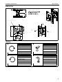
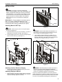
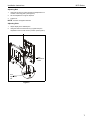
INSTALLATION INSTRUCTIONS
Instrucciones de instalación
Installationsanleitung
Instruções de Instalação
Istruzioni di installazione
Installatie-instructies
Instructions d´installation
Dual Ceiling Mount
Spanish Product Description
German Product Description
Portuguese Product Description
Italian Product Description
Dutch Product Description
French Product Description
MCD Series
MCD Series
Installation Instructions
DISCLAIMER
Milestone AV Technologies and its affiliated corporations and
subsidiaries (collectively "Milestone"), intend to make this
manual accurate and complete. However, Milestone makes no
claim that the information contained herein covers all details,
conditions or variations, nor does it provide for every possible
contingency in connection with the installation or use of this
product. The information contained in this document is subject
to change without notice or obligation of any kind. Milestone
makes no representation of warranty, expressed or implied,
regarding the information contained herein. Milestone assumes
no responsibility for accuracy, completeness or sufficiency of
the information contained in this document.
Chief® is a registered trademark of Milestone AV Technologies.
All rights reserved.
IMPORTANT SAFETY INSTRUCTIONS
WARNING: A WARNING alerts you to the possibility of
serious injury or death if you do not follow the instructions.
CAUTION: A CAUTION alerts you to the possibility of
damage or destruction of equipment if you do not follow the
corresponding instructions.
WARNING: Failure to read, thoroughly understand, and
follow all instructions can result in serious personal injury,
damage to equipment, or voiding of factory warranty! It is the
installer’s responsibility to make sure all components are
properly assembled and installed using the instructions
provided.
WARNING: Failure to provide adequate structural strength
for this component can result in serious personal injury or
damage to equipment! It is the installer’s responsibility to
make sure the structure to which this component is attached
can support five times the combined weight of all equipment.
Reinforce the structure as required before installing the
component.
WARNING: Exceeding the weight capacity can result in
serious personal injury or damage to equipment! It is the
installer’s responsibility to make sure the combined weight of all
components located between the supporting structure and the
mount does not exceed 250 lbs (113.4 kg) [125 lbs (56.7 kg)
each faceplate].
•
2
The weight capacity of the mount may be LIMITED to
the lowest capacity of any other component located
between the mount and the supporting structure!
WARNING: Use this mounting system only for its intended
use as described in these instructions. Do not use
attachments not recommended by the manufacturer.
WARNING: Never operate this mounting system if it is
damaged. Return the mounting system to a service center for
examination and repair.
WARNING: Do not use this product outdoors.
--SAVE THESE INSTRUCTIONS--
Installation Instructions
MCD Series
DIMENSIONS
NOTE: CUSTOM INTERFACE BRACKET
NOT SHOWN. THE CUSTOM INTERFACE
BRACKET NEEDED FOR YOUR DISPLAY
WILL ADD BETWEEN 1/2" AND 2" IN
1-1/2" NPSM
8.02
4.01
TOP MOUNTING BUTTON ON
MSB-XXXX DRAWING GOES HERE
1.01
FACE TILTS
5 UP
20 DOWN
FACE TILTS
5 UP
20 DOWN
APPROXIMATE CENTER
OF DISPLAY
10.15
LEGEND
Tighten Fastener
Open-Ended Wrench
Apretar elemento de fijación
Llave de boca
Befestigungsteil festziehen
Gabelschlüssel
Apertar fixador
Chave de bocas
Serrare il fissaggio
Chiave a punte aperte
Bevestiging vastdraaien
Steeksleutel
Serrez les fixations
Clé à fourche
Loosen Fastener
Hex-Head Wrench
Aflojar elemento de fijación
Llave de cabeza hexagonal
Befestigungsteil lösen
Sechskantschlüssel
Desapertar fixador
Chave de cabeça sextavada
Allentare il fissaggio
Chiave esagonale
Bevestiging losdraaien
Zeskantsleutel
Desserrez les fixations
Clé à tête hexagonale
3
MCD Series
Installation Instructions
TOOLS REQUIRED FOR INSTALLATION
5/32"
(Included)
9/16"
PARTS
B (1)
5/16-18 x 3/8"
C (1)
5/32"
A (1)
[MCD Mount]
4
Installation Instructions
MCD Series
INSTALLATION
WARNING: FAILURE TO PROVIDE ADEQUATE
1
STRUCTURAL STRENGTH FOR THIS COMPONENT CAN
RESULT IN SERIOUS PERSONAL INJURY OR DAMAGE
TO EQUIPMENT! It is the installer’s responsibility to make
sure the structure to which this component is attached can
support five times the combined weight of all equipment.
Reinforce the structure as required before installing the
component.
(A)
IMPORTANT ! : These installation instructions assume
that a 1-1/2" NPT or NPSM (Schedule 40, 0.154"
minimum thickness aluminum - ASTM B221) pipe (not
included) has been properly installed and is in place.
Display
Attaching Mount to NPT Pipe
Figure 2
CAUTION: Watch for pinch points. Do not place fingers
between moveable parts.
WARNING: DISPLAY MAY WEIGH IN EXCESS OF 40
1.
Thread the MCD mount (A) onto the existing 1-1/2" NPT or
NPSM pipe (not included) until tight. (See Figure 1)
2.
Install and tighten the 5/16-18 x 3/8" set screw (B) using the
5/32" hex head wrench (C). (See Figure 1)
LBS! Always use two people and proper lifting techniques
when installing or positioning display on mount.
2.
Lower display into place listening for audible "click" to
ensure recessed area of mounting buttons are properly
seated in lower area of mounting holes and ClickConnect
mechanism has engaged. (See Fig. 2, 3 and 4)
NPT
Pipe
Interface Bracket
(will vary in
appearance)
(A)
2
1
(B) x 1
Back
of Display
(A)
Figure 3
Figure 1
Attaching Interface Bracket to Display
1.
Attach interface bracket to display following instructions
included with interface bracket kit.
Attaching Displays to Mount
1.
While supporting both sides of display, align four mounting
buttons on display or interface bracket with four mounting
holes in mount. (See Figures 2, 3 and 4)
WARNING: IMPROPER INSTALLATION CAN LEAD TO
DISPLAY FALLING CAUSING SERIOUS PERSONAL
INJURY OR DAMAGE TO EQUIPMENT! Ensure mounting
buttons are completely engaged in mounting holes.
Holes are provided in the faceplate for use with a padlock or
similar locking device, if desired. In addition, the pin and nut may
be removed from the upper holes and moved to the lower holes
for use as a more permanent locking device. (See Figure 4).
5
MCD Series
Installation Instructions
Remove bolt
1 or padlock
if used
To use as a more
permanent lock, remove
pin and nuts and move
to lower holes.
2
4
5
A padlock or bolt may
be placed through latch holes
Pin in
"Closed"
position Move to
"Open"
position to
remove
display
4
Figure 4
Removing Display
1.
Disconnect all power/audio/video cables.
2.
Remove bolt or padlock from faceplate (if used).
(See Figure 5)
NOTE: The pin may have been used as a more permanent
locking device. If so, remove nut and pin and move
from the lower holes to the upper holes.
3.
Pull back on flag on upper mounting hole and press pin
down into "Open" position. (See Figure 5)
WARNING: THE DISPLAY MAY WEIGH IN EXCESS OF
Pin in
"Open"
position Move to
"Closed"
position
after display
is removed
40 LBS EACH! Always use two people and proper lifting
techniques when installing or positioning display.
4.
Carefully lift display from mount.
5.
Lift up on pin and place flag back against faceplate to return
it to "Closed" position. (See Figure 5)
Figure 5
Adjusting Display
CAUTION: Watch for pinch points. Do not place fingers
between moveable parts.
6
Installation Instructions
MCD Series
Adjusting Roll
1.
Using a 9/16" wrench, loosen the Nylock roll adjustment nut
on back of mounting plate. (See Figure 6)
2.
Tilt the faceplate left or right as required.
3.
TIghten nut.
NOTE: Do NOT overtighten fasteners.
Adjusting Pitch
1.
Adjust display to the desired pitch.
2.
Using the 5/32" hex head wrench (C), tighten the pitch
adjustment screw to hold mount in position. (See Figure 6)
Pitch
Adjustment
Screw
Roll
Adjustment
Nut
Figure 6
7
MCD Series
Installation Instructions
USA/International
Europe
Chief Manufacturing, a products division
of Milestone AV Technologies
8800-002113 Rev00
2011 Milestone AV Technologies, a
Duchossois Group Company
www.chiefmfg.com
11/11
Asia Pacific
A
P
F
A
P
F
A
8401 Eagle Creek Parkway, Savage, MN 55378
800.582.6480 / 952.894.6280
877.894.6918 / 952.894.6918
Franklinstraat 14, 6003 DK Weert, Netherlands
+31 (0) 495 580 852
+31 (0) 495 580 845
Office No. 1 on 12/F, Shatin Galleria
18-24 Shan Mei Street
Fotan, Shatin, Hong Kong
P 852 2145 4099
F 852 2145 4477