1
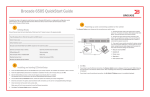
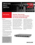
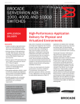
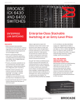
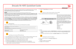
Brocade 6505 QuickStart Guide
®
Complete the steps in this guide to install and set up your Brocade 6505 switch in a single-switch configuration using
EZSwitchSetup. See the Brocade 6505 Hardware Reference Manual and the Fabric OS Administrator’s Guide
if you want to choose a different setup.
1
Getting Ready
3
Powering up and connecting cables to the switch
The Connect Cables screen shows you the connections you need to make.
1. Connect the power cord to the switch and to a power
source (1). The power and status LEDs display amber then
green. This can take from one to three minutes.
Ensure that you have the items listed below. Write down the IP network values in the space provided.
2. Connect the switch and the setup computer to the
same LAN, using Ethernet cables (3, 5) and an Ethernet
hub or switch (2). Be sure the Ethernet hub or switch is
connected to a power source (6).
Fixed IP address (IPv4 or IPv6) for the switch (no DHCP server): __________________________________________________
Subnet mask value: ______________________________________________________________________________________
Default Gateway value: ___________________________________________________________________________________
1
Brocade switch World Wide Name (WWN): located on the switch ID pullout: ________________________________________
Ethernet connection (hub or switch)
Ethernet and Fibre Channel Cables
EZSwitchSetup CD
Setup computer
Host computer with an installed HBA
Disk array
Standard screw driver
Optical transceivers (SFPs)
2
Installing and starting EZSwitchSetup
1. Insert the EZSwitchSetup CD into the CD-ROM drive of your setup computer. The installer will autostart in about a minute.
2. Follow the EZSwitchSetup directions for installation. Installation will take a few minutes after you click OK.
3. Wait for EZSwitchSetup to start, which should happen automatically after it is installed.
For Windows and Linux instructions, refer to the EZSwitchSetup Administrator’s Guide.
4. On the EZSwitchSetup Introduction screen, choose the option that matches your setup configuration:
• Ethernet connection. This option uses the Ethernet LAN connection you will use for running EZSwitchSetup Manager.
• Direct connection to the switch with a serial cable.
Most users will find it more convenient to use the Ethernet connection.
5. Click Next. The Connect Cables screen is displayed.
4
7
3
6
5
Browser that allows pop-up windows
2
3. If you want to use a serial connection for setup, connect
your setup computer COM port (7) to the serial port on the
switch, using the serial cable shipped with the switch (4).
The serial connection settings are as follows:
•
•
•
•
•
Bits per second: 9600
Databits: 8
Parity: none
Stop bits: 1
Flow control: none
4. Click Next.
• If you chose to use the Ethernet connection, the Discover Switch screen is displayed. Enter the switch WWN, following
the instructions on the Discover Switch screen. After completing switch discovery, the Set Switch IP Address screen
is displayed.
• If you chose to use the serial port connection, the Set Switch IP Address screen is immediately displayed.
®
4
1. Install the SFP+ transceivers in the Fibre Channel ports on the switch to match the ports shown onscreen.
Setting the switch IP address
!
a.
1. Enter the required information on the Set Switch IP Address screen.
2. If prompted to install Active X or a version of the Java runtime environment, do so. Reboot the setup computer, if required.
3. Click Next.
The Confirm IP Address screen is displayed.
If you are using 16 Gbps SFP+ transceivers, you may want to connect
the cable to the SFP+ first, and then insert them into the port as a unit.
4. Click Next to confirm the addresses.
A Continue Configuration screen is displayed.
If you are using 8 Gbps SFP+ transceivers, close the latching wire bail.
5. Click Continue with EZManager.
5
Set the switch password
b.
The Set Parameters screen is displayed.
2. Create a new administrator account password in the Set Parameters screen.
!
a.
Remove plastic protector caps from the Fibre Channel cable ends (if any),
and position the cable connector so that it is oriented correctly.
b.
Insert the cable connector into the SFP+ until it is firmly seated and
the latching mechanism clicks.
c.
The Configure Ports and Connect Devices screen shows missing,
valid, and invalid connections as you cable the switch. Note that it
can take up to 15 seconds for the connection to display as a valid
connection. Verify that the connections are all green and click Next.
3. Enter a new name for the switch (optional step).
4. Adjust the date and time for your time zone (optional step).
5. Click Next.
Configure the zones and perform device selection
1. Select Typical Zoning on the Select Zoning screen and click Next.
Typical Zoning is the default zone configuration.
2. Enter the number and types of devices that you are connecting to the switch on the Device Selection screen.
EZSwitchSetup uses these values to automatically configure the ports on your switch.
7
Connect devices
The Connect Devices screen displays a graphical representation of the switch with the device connections based on the
information that you entered when you configured zones and performed device selection. The screen will show all physical
connections as missing until you connect the devices that you specified.
Repeat for the other ports.
2. Make the physical connections to your host and storage devices. Match the physical connections shown on the
Configure Ports and Connect Devices screen.
1. Click Next on the EZManager Welcome to Switch Configuration screen.
6
The 16 Gbps SFP+ transceivers have a long pull tab and no latching
wire bail. Remove any protector plugs from the SFP+ transceivers you
are going to use, and position and insert each SFP+ transceiver as
required (right side up in the top row of ports and upside down in the
bottom row of ports). Use the pull tab on the 16 Gbps SFP+ tranceivers
to help push the transceiver into the port.
3. The Finish screen will display this message: “Congratulations - you’ve successfully completed the setup!” If you used the
serial connection for setup, you can remove the serial cable.
Additional configuration options, such as custom zoning, are available from EZManager. See the EZSwitchSetup
Administrator’s Guide for more information on custom zoning, and other switch configuration and management options.
© 2011 Brocade Communications Systems, Inc. All Rights Reserved.
53-1002450-01
*53-1002450-01*
Brocade, the B-wing symbol, BigIron, DCX, Fabric OS, FastIron, NetIron, SAN Health, ServerIron, and TurboIron are registered trademarks, and AnyIO,
Brocade Assurance, Brocade NET Health, Brocade One, CloudPlex, MLX, VCS, VDX, and When the Mission Is Critical, the Network Is Brocade are trademarks of
Brocade Communications Systems, Inc., in the United States and/or in other countries. Other brands, products, or service names mentioned are or may be
trademarks or service marks of their respective owners.