1
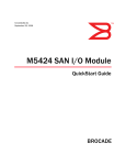
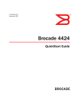
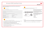
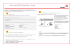
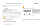
Brocade VA-40FC QuickStart Guide
Complete the steps in this guide to install and setup your Brocade VA-40FC switch using EZSwitchSetup. Refer to the Brocade
VA-40FC Hardware Reference Manual and the Fabric OS Administrator’s Guide (located on the Brocade VA-40FC
Documentation CD) if you want to choose a different set up.
5. Click Next. The Connect Cables screen is displayed.
3
ATTENTION
The Brocade VA-40FC comes pre-configured in Access Gateway mode with the default F_Port-to-N_Port mappings (shown in Step
5 of this guide). You do not need to configure Access Gateway if you use the default F_Port-to-N_Port mappings. You can change
the default configuration using command line interface (CLI) or WebTools, after launching EZSwitchSetup as described below to
configure an IP address that is reachable on your network.
Power up and connect cables to the switch
The Connect Cables screen shows you the connections you need to make.
1.Connect the power cord to the switch and then to the
power source (1). The power and status LEDs display
amber then green. This can take from one to 3 minutes.
Access Gateway mode can only be enabled or disabled when the VA-FC40 is in a disabled state. To deploy the Brocade VA-40FC
as a traditional fabric switch with all fabric services enabled but without Access Gateway functionality, enter the switchDisable
and then ag --modeDisable commands or perform the equivalent operations in WebTools. To deploy the switch in Access Gateway
mode, enter the switchDisable command on the VA-40FC and enter the ag –modeEnable command or its WebTools equivalent.
These operations are data disruptive and trigger an automatic reboot of the VA-40FC before it comes up in the new mode.
1
2.Connect the switch and the set up computer to the
same LAN, using Ethernet cables (3, 5) and an Ethernet
hub or switch (2). Be sure the Ethernet hub or switch is
connected to a power source (6).
3.If you want to use a serial connection for setup,
connect your set up computer COM port (7) to the serial
port on the switch, using the serial cable shipped with
the switch (4). The serial connections settings are as
follows:
Getting Ready
•Bits per second: 9600
•Databits: 8
•Parity: none
•Stop bits: 1
•Flow control: none
Before you start the installation and setup of your switch, ensure the following items are available.
Fixed IP address (IPv4 or IPv6) for the switch (no DHCP server): _________________________________________________________________
Subnet mask value: ___________________________________________________________________________________________________
Default Gateway value: ________________________________________________________________________________________________
Brocade switch World Wide Name (WWN) located on the switch ID pullout: ________________________________________________________
Ethernet connection (hub or switch)
EZSwitchSetup CD
Browser that allows pop-up windows
2
Ethernet and Fibre Channel cables
Set up computer
Optical transceivers (SFPs)
4. Click Next.
• If you chose the Ethernet connection, the Discover Switch screen is displayed. Enter the switch WWN, following the
instructions on the Discover Switch screen. After completing switch discovery, the Set Switch IP Address screen is
displayed.
• If you chose to use the serial port connection, the Set Switch IP Address screen is immediately displayed.
Installing and starting EZSwitchSetup
1. Insert the EZSwitchSetup CD into the CD-ROM drive of your set up computer. The installer will autostart in about a minute.
2. Follow the EZSwitchSetup directions for installation. Installation will take a few minutes after you click OK.
3. Wait for EZSwitchSetup to start, which should happen automatically after it is installed.
For Windows and Linux instructions, refer to the EZSwitchSetup Administrator’s Guide.
4. On the EZSwitchSetup Introduction screen, choose the option that matches your set up configuration:
• Ethernet connection. This option uses the Ethernet LAN connection used for running EZSwitchSetup Manager.
• Direct connection to the switch with a serial cable.
4
Setting the switch IP address
1. Enter the required information on the Set Switch IP Address screen.
2. Click Next.
The Confirm IP Address screen is displayed.
3. Click Next to confirm the addresses.
A Continue Configuration screen is displayed. After you click Next, you might be prompted for the current admin password
before the Confirm IP Address screen is displayed, but only if you have already changed it from the default value
(“password”).
2. Connect Fibre Channel cables. Using a mapping scheme appropriate for your installation, connect servers to ports in the
F_port group, and edge switches to ports in the N-port group (refer to figure in step five).
Since the Brocade VA-40FC is pre-configured in Access Gateway mode, the default Continue Configuration option launches
WebTools to manage the switch. Or you can choose Exit EZSwitchSetup, connect to the switch using Telnet, and use the CLI. For
more information on WebTools, refer to the Web Tools Administrator’s Guide.
5
!
a.
Remove plastic protector caps from the Fibre Channel
cable ends (if there are any), and position the cable
connector so that it is oriented correctly.
b.
Insert the cable connector into the SFP until it is firmly
seated and the latching mechanism clicks.
Review and configure default port mappings
The following diagram summarizes the default port assignments and mappings for Access Gateway on the Brocade VA-40FC.
The F_ports connect to servers and the N_ports connect to fabrics. To display these mappings in CLI enter
ag - -mapshow, or in WebTools click on the F_Port to N_Port Mappings button in Port Administration. The default configurations
work with no further configuration as long as the connections from server to fabric are correct.
7
.
Default mapping:
0-3 to 32
8-11 to 34
4-7 to 33 12-15 to 35
0
1
2
3
8
9
10
11
16
17
18
19
24
25
26
27
32
33
34
35
4
5
6
7
12
13
14
15
20
21
22
23
28
29
30
31
36
37
38
39
Ports 0-31 are F_ports
16-19 to 36
20-23 to 37
24-27 to 38
28-31 to 39
Ports 32-39 are N_ports
with failover and
failback enabled.
Bring up the Management Interface
1. You can use either Web Tools or CLI to manage the switch. If you prefer to work from the CLI, launch a Telnet window, and
log in to the switch IP address through Telnet. In either case, use the default admin user name and password, unless you
have already changed them.
2. If you logged in with the default password, change it now. As a precaution, you may want to write down the password and
store it in a secure location for future reference.
ATTENTION
The Port Group policy is enabled by default with the mapping described above. For more information on how to manage the
policies, refer to the Access Gateway Administrator’s Guide.
6
8
Administering Access Gateway
Refer to the Access Gateway Administrator’s Guide for detailed information about Access Gateway concepts, configuration
procedures, and administrative operations
Connect Devices
1. Install the SFP transceivers in the Fibre Channel ports on the switch.
!
a.
1a
b.
Remove any protector plugs from the SFP
transceivers you are going to use, and position and
insert each SFP transceivers as required (right side
up in the top row of ports and upside down in the
bottom row of ports) until it is firmly seated.
Close the latching bale.
.
© 2009 Brocade Communications Systems, Inc. All Rights Reserved.
53-1001532-01
*53-1001532-01*
4- 01
Brocade, Fabric OS, File Lifecycle Manager, MyView, and StorageX are registered trademarks and the Brocade B-wing symbol, DCX, and SAN Health are trademarks
of Brocade Communications Systems, Inc., in the United States and/or in other countries. All other brands, products, or service names are or may be trademarks or
service marks of, and are used to identify, products or services of their respective owners.