1
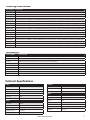
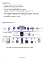
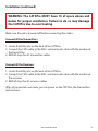
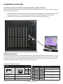
Installation Manual CATXPro 64-port HDTV CAT5 Matrix Switch with RS-232, IR, USB, TCP/IP and Touch Control For WUXGA, Component Video, Composite Video and S-Video with full stereo audio support and full IR/RS232 non-blocking matrix switching Switch up to 64 remote devices to 64 remote displays located up to 1,000 feet away. www.smartavi.com Introduction Features CATXPro routes audio, video, IR and RS/232 signals from several different video sources out to multiple displays (projectors, monitors, etc.) and speakers via inexpensive Cat5/6 UTP cable. CATXPro is capable of connecting to as many as 64 video sources via transmitters and 64 video displays via receivers with a maximum extension of 1,000 feet between the transmitter and receiver units. A single audio/video output can be routed to one or multiple destinations. Video is transmitted at a resolution of 1920 x 1200 to insure high resolution images. Buffered video outputs and analog delivery of stereo audio maintains optimum integrity throughout the system. Special remote boxes offer compatibility with Video Composite , UXGA, Component Video and S-Video. • • • • • • • • • • • • • • • Supports high resolution video up to 1920x1200 High quality audio switching Infrared, RS232 and TCP/IP control PC Windows software control Integral UTP distribution 9U rackmounted chassis Uses easy to install, inexpensive CAT-5/5e/6/7/8 Maximum extension of 1,000 feet (300m) between the local and remote units HDTV compatible. (720p, 1080i,1080p) 300 MHz bandwidth Compatible with VGA, XGA, Sun, MAC and SGI Compatible with Line Level Stereo Audio Signals High ground loop immunity Built-in power surge and transient protection Designated trimmer in the remote unit to compensate for length CATXPro Rear 2 www.smartavi.com Ordering Information PART NUMBER DESCRIPTION CSWX16X16S CAT5 Audio/Video and IR/RS232 16 IN X 16 OUT Matrix with RS-232 Control. Includes: [CSWX16X16, (SM-CSW) & (CCPWR06US)] CSWX16X32S CAT5 Audio/Video and IR/RS232 16 IN X 32 OUT Matrix with RS-232 Control. Includes: [CSWX16X32, (SM-CSW) & (CCPWR06US)] CSWX16X48S CAT5 Audio/Video and IR/RS232 16 IN X 48 OUT Matrix with RS-232 Control. Includes: [CSWX16X48, (SM-CSW) & (CCPWR06US)] CSWX16X64S CAT5 Audio/Video and IR/RS232 16 IN X 64 OUT Matrix with RS-232 Control. Includes: [CSWX16X64, (SM-CSW) & (CCPWR06US)] CSWX32X16S CAT5 Audio/Video and IR/RS232 32 IN X 16 OUT Matrix with RS-232 Control. Includes: [CSWX32X16, (SM-CSW) & (CCPWR06US)] CSWX32X32S CAT5 Audio/Video and IR/RS232 32 IN X 32 OUT Matrix with RS-232 Control. Includes: [CSWX32X32, (SM-CSW) & (CCPWR06US)] CSWX32X48S CAT5 Audio/Video and IR/RS232 32 IN X 48 OUT Matrix with RS-232 Control. Includes: [CSWX32X48, (SM-CSW) & (CCPWR06US)] CSWX32X64S CAT5 Audio/Video and IR/RS232 32 IN X 64 OUT Matrix with RS-232 Control. Includes: [CSWX32X64, (SM-CSW) & (CCPWR06US)] CSWX48X16S CAT5 Audio/Video and IR/RS232 48 IN X 16 OUT Matrix with RS-232 Control. Includes: [CSWX48X16, (SM-CSW) & (CCPWR06US)] CSWX48X32S CAT5 Audio/Video and IR/RS232 48 IN X 32 OUT Matrix with RS-232 Control. Includes: [CSWX48X32, (SM-CSW) & (CCPWR06US)] CSWX48X48S CAT5 Audio/Video and IR/RS232 48 IN X 48 OUT Matrix with RS-232 Control. Includes: [CSWX48X48, (SM-CSW) & (CCPWR06US)] CSWX48X64S CAT5 Audio/Video and IR/RS232 48 IN X 64 OUT Matrix with RS-232 Control. Includes: [CSWX48X64, (SM-CSW) & (CCPWR06US)] CSWX64X16S CAT5 Audio/Video and IR/RS232 64 IN X 16 OUT Matrix with RS-232 Control. Includes: [CSWX64X16, (SM-CSW) & (CCPWR06US)] CSWX64X32S CAT5 Audio/Video and IR/RS232 64 IN X 32 OUT Matrix with RS-232 Control. Includes: [CSWX64X32, (SM-CSW) & (CCPWR06US)] CSWX64X48S CAT5 Audio/Video and IR/RS232 64 IN X 48 OUT Matrix with RS-232 Control. Includes: [CSWX64X48, (SM-CSW) & (CCPWR06US)] CSWX64X64S CAT5 Audio/Video and IR/RS232 64 IN X 64 OUT Matrix with RS-232 Control. Includes: [CSWX64X64, (SM-CSW) & (CCPWR06US)] Accessories PART NUMBER DESCRIPTION XTP-TXS XTPRO UXGA/Audio/RS232/IR tranmitter with Local Video . Includes:[ XTP-RX and (PS5VD1A)] XTP-RXS XTPRO UXGA/Audio/RS232/IR receiver with Dual Video Includes:[ XTP-RX and (PS5VD1A)] XTP-RXLS UXGA/Audio/RS232/IR Long Range receiver. Includes:[ XTP-RXL and (PS5VD1A)] XTX-RXS XT Xpress UXGA/Audio receiver. Includes:[ XTJ-RX and (PS5VD1A)] XTJ-TXS XT UXGA/Audio tranmitter. Includes:[ XTJ-RX and (PS5VD1A)] SM-TCPS TCP/IP Control include SMTCP, (CCRS232MM ) and (PS5VD1A)] SM-EYE External infrared receiver. IR range of 10’ to 30’ RMT-2 Remote control device XTP-RXXS Xtreem UXGA/Audio/RS-232/IR CAT5 1699ft Receiver with Remote Control for Skew Setting. Includes: [XTP-RXX, SMRMT, & (PS5VD2A)] Technical Specifications VIDEO CONTROL Bandwidth 250MHz RS232 Via Software @ 9600 bps Input Signal Level 1 Volt pk pk into 75R IR Via Remote Control with IR-EYE Type 3 Output Impedance 100 Ohms USB Via TCP/IP (optional) Input Impedance 75 Ohms OTHER Connector RJ45 Power Internal 100-240 VAC Format VGA/SVGA/XGA/WUXGA/RGB/Hv/RGsB Dimensions 17”W x 15.75”H (9U) x 14”D Weight 20 lbs. Approvals UL, CE, ROHS Compliant Operating Temp. 32-131°F (0-55 °C) Storage Temp. -4-185 °F (-20-85 °C) Humidity Up to 95% AUDIO Bandwidth 20KHz Signal Level 0dB Output Impedance 100 Ohms Input Impedance 10K Ohms Connector RJ45 www.smartavi.com 3 Applications • • • • • • • • Corporate or Educational Presentations Financial (Remote Servers/User Control) Call Centers for Technical Support Industrial (Long-Range Workstation Isolation) Airport Installations (Air Traffic Control/Passenger Information) KVM Extension where Exceptional Quality of Signal is Crucial Medical (Remote Operation Away from Sensitive/Magnetic Equipment) Recording (for Large Studios where Editing/Mixing Stations are Compact and/or Require Complete Silence) Application Diagram HDTV Display CRT Display Security Monitor ...up to 64 Outputs Television XTPro Receiver LCD Display CONTROL Total 1,000 Feet CATXPro ...up to 64 Inputs XTPro Transmitter TCP/IP Security Camera Rack Servers Laptop Desktop Computer DVR Player RS-232 Infrared Gaming Console VGA Input to VGA Output and RGB Input to RGB Output 4 www.smartavi.com Camera Installation Connecting XTAV transmitter Connecting The Transmitter 1. Connect the output of the computer video card to the video input of the transmitter using the included male to male video cable. 2. Connect the output of the computer audio card to the audio input of the transmitter using 3.5mm audio male to male audio cable. 3. Connect external speakers to the transmitter’s audio out (Standard 3.5mm stereo miniplug). 4. In the back of the unit connect the CAT5 cable that will connect to the CATXPro. Connecting the XTAV receiver Connecting The Receiver 1. Connect CAT5 cable (coming from the CATXPro) to the back of the receiver. 2. Connect display monitors to the VGA out connector on the front of the receiver. 3. Connect external speakers to the audio output connections on the front of the unit. (Standard 3.5mm stereo Miniplug) Adjusting and Tuning the Signal (Skew) In order to fine tune the signal, adjust the individual dials one at a time starting with GREEN, then BLUE, and lastly RED. As you turn the dials you will notice the colors slightly change as you increase or decrease the strength. All dials should be approximately the same value. www.smartavi.com 5 Installation (continued) Connecting XTWALL Transmitter Connecting The Transmitter 1. Connect the output of the computer video card to the video input of the transmitter using the included male to male video cable. 2. Connect the output of the computer audio card to the audio input of the transmitter using 3.5mm audio male to male audio cable. 3. Connect local monitor to the VGA out of the transmitter. 4. Connect external speakers to the transmitter’s audio out (Standard 3.5mm stereo miniplug). 5. In the back of the unit connect the CAT5 cable that will connect to the CATXPro. *NOTE: You can not use RS232 and IR at the same time. Connecting XTWALL Receiver Connecting The Receiver 1. Connect CAT5 cable (coming from the CATXPro) to the back of the receiver. 2. Connect 1-2 display monitors to the VGA out connectors on the front of the receiver. 3. Connect 1-2 sets of external speakers to the audio output connections on the front of the unit. (Standard 3.5mm stereo Miniplug) Adjusting and Tuning the Signal (Skew) In order to fine tune the signal, adjust the individual dials one at a time starting with GREEN, then BLUE, and lastly RED. As you turn the dials you will notice the colors slightly change as you increase or decrease the strength. All dials should be approximately the same value. 6 www.smartavi.com Installation (continued) Connecting the XTPro transmitter Connecting The Transmitter 1. Connect the output of the computer video card to the video input of the transmitter using the included male to male video cable. 2. Connect the output of the computer audio card to the audio input of the transmitter using 3.5mm audio male to male audio cable. 3. Connect local monitor to the VGA out of the transmitter. 4. Connect external speakers to the transmitter’s audio out (Standard 3.5mm stereo miniplug). 5. In the back of the unit connect the CAT5 cable that will connect to the CATXPro. *NOTE: You can not use RS232 and IR at the same time. Connecting the XTPro receiver Connecting The Receiver 1. Connect CAT5 cable (coming from the CATXPro) to the back of the receiver. 2. Connect 1-2 display monitors to the VGA out connectors on the front of the receiver. 3. Connect 1-2 sets of external speakers to the audio output connections on the front of the unit. (Standard 3.5mm stereo Miniplug XTPro RX Adjusting and Tuning the Signal (Skew) In order to fine tune the signal, adjust the individual dials one at a time starting with GREEN, then BLUE, and lastly RED. As you turn the dials you will notice the colors slightly change as you increase or decrease the strength. All dials should be approximately the same value. www.smartavi.com 7 ower Supply Installation (continued) emote Control Connecting the XTPro-XTREEM receiver PS-5VDC2A RMT-2 Connecting The Receiver 1. Connect CAT5 cable (coming from the CATXPro) to the back of the receiver. 2. Connect a display monitor to the VGA out connectors on the front of the receiver. 3. Connect a set of external speakers to the audio output connections on the front of the unit. (Standard 3.5mm stereo Miniplug Diagram Adjusting and Tuning the Signal (Skew) In order to fine tune the signal, adjust the individual dials one at a time starting with GREEN, then BLUE, and lastly RED. As you turn the dials you will notice the colors slightly change as you increase or decrease the strength. All dials should be approximately the same value. 8 www.smartavi.com Impe Installation (continued) WARNING: The CATXPro MUST have 1U of space above and below for proper ventilation. Failure to do so may damage the CATXPro due to over heating. Make sure the unit is powered off before connecting the cables Connect all the Transmitters 1. Locate the RJ45 jacks on the back of the CATXPro, 2. Connect the CAT5 cable to the RJ45 and mark each cable with the number of the transmitter 3. REPEAT steps for all transmitters cables Connect all the Receivers 1. Locate the RJ45 jacks on the back of the CATXPro, 2. Connect the CAT5 cable to the RJ45 and mark each cable with the number of the receivers 3. REPEAT steps for all receivers cables After all connections are made, you can power on the CATXPro, the transmitters and receivers. www.smartavi.com 9 Installation (continued) Connecting the Control Communication Cable: RS-232 Each unit can be controlled by a RS-232 port connected from the back of the chassis. The SmartControlPro software will be used to control the units. 1. Connect the RS-232 cable the control computer by connecting the female RS-232 connector into the male RS232 connector of the PC. Turn the side screws so that it does not accidentally become disconnected 2. Connect RS-232 cable connector to the male RS-232 connector on the back of the chassis. CAT5 Preparation The CATXPro is a point to point video extender/switcher. The system does not allow to connecting the Cat5 via hubs or any kind of switches that the point to point connection need be maintained. The 16 RJ45 ports on the front of the CATXPro are output ports, providing connectivity to the XTPro or XT-AV receiver. This is a standard RJ45 connector, the CATXPro can be connected via either CAT5, CAT5e or CAT6 cabling. CAT5/5e/6 CABLE SPECIFICATIONS CONNECTOR RJ-45 MALE PAIR RJ-45 FEMALE 87654321 CAPACITANCE 12345678 14 pf/ft (46.2 pf/m) CONDUCTOR GAUGE 24 AWG IMPEDANCE 100 +/- 15 ohms 10 PINS SmartAVI Proprietary Connector 1 1&2 Pair 2 3&6 1 3 4&5 4 7&8 Color RJ45 Pin White/Orange 1 Orange 2 White/Green 3 Green 6 Description Video+Audio 2 Video+Audio Blue 4 White/Blue 5 White/Brown 7 Brown 8 3 Video+Audio 4 www.smartavi.com DATA RS232 and IR Bidirectional Software Operation For the latest software, contact SmartAVI for a download link. Open the downloaded file in order to initiate software installation. Click Install. After installation has completed, click CLOSE. In order to use the software, click on the START button>Programs>SmartControl Pro. There you should see a help file, the SmartControl Pro launcher as well as a shortcut to uninstall SmartControl Pro. Click on SmartControl Pro in order to launch the software. When the software starts you will see a screen like this. The display may say 16 Inputs and 16 Outputs, please change these values to 64 and 64. 64 Cat Switch 64 Advanced Configuration: If you have more than one Router installed you will want to check this box. Router Type: Select “Cat Switch” A/V Split: Check this box if you need to route audio and video independently, regardless from which source they originated from. Leave unchecked if you want audio and video signals from the same input to remain together. For example, if you wanted to route different video feeds to different locations but wanted all of them to have the same audio, you should check the box. www.smartavi.com 11 Software Operation (continued) Inputs/Outputs: Enter the number of Inputs/Outputs your CATXPro has. Although the CATXPro can have up to 64 inputs and 64 outputs, for this instruction we will assume that there are 16 inputs and 16 outputs. Com Port: Select the appropriate com port that your computer is using to access the router. Router Time out: By default this is 0 meaning the computer acknowledges commands almost instantly. Sometimes a computer takes longer to respond. This setting should be left at 0. If you need to change it, it should be no higher than 0.2. After you have entered in the necessary information click OK. This will now take you to the Main Routing Window where you can route the different video/audio connections. Main CATXPro window On this screen you will notice the input buttons running down the left side while the output buttons run across the top. They are each labeled 1 through 16. 12 www.smartavi.com Software Operation (continued) The Main Routing Window enables you to control the router(s) connections by means of the CATXPro panel, the button panel, or with pre-recorded routes called macros. CATXPro Panel: This is probably the simplest way to route the connections. Simply click on the cross point itself. The input on the left will then be routed to the output above. Note: Inputs can be routed to several different outputs, but each output can only have a single input at any one time. So you can have several connections horizontally but not vertically. The Button Panel: These are the numbered buttons across the top and left sides. Click an output button on the top, and then click an input button on the left. Options for using the Button Panel • Output Options: To select multiple outputs next to each other, click on one output, then hold the shift key down and click the last output. When the input is clicked, it is routed to all selected outputs. To select multiple outputs individually, hold the control key down and click on any number of outputs. When the input is clicked, it is routed to all selected outputs. • Input Options: To route an input to all the outputs at once, hold the control key down and click on an input. To leave the outputs selected after the route is made, hold the shift key down and click on an input. www.smartavi.com 13 Controlling the CATXPro with the SMTCP module The SMTCP-2 is an RS-232 control module that allows most SmartAVI switching matrixes to be controlled remotely via HTTP or TELNET. Manage the switching functions of your matrix with ease from anywhere in the world. With the SMTCP-2 you can save up to 10 preset input/output configurations for easy access. TELNET access provides transparent command control of your matrix, perfect for use with automated third-party control software. Features Applications • • • • • • • • • • • • • • • Supports HTTP and TELNET control 10/100 Ethernet Interface Up to 10 user-definable configurations Password Protected Up to 5 Users can Control the Matrixes IP Configuration via TCP/IP and RS-232 Flexible control of several types of matrixes Technical Specifications Power External 100-240 VAC/5VDC2A @10W Dimensions 2.8125”W x 1”H x 3.375”D Weight 0.5 lbs Approvals UL, CE, ROHS Compliant Operating Temp. 32-131°F (0-55 °C) Storage Temp. -4-185 °F (-20-85 °C) Humidity Up to 95% 14 www.smartavi.com Server Collocation Digital Signage Airports Dealer Rooms Control Rooms Audio/Visual Presentations Hotels/Resorts KVM Switches Controlling the CATXPro with the SMTCP module (continued) Connecting to the SMTCP-2 for the first time The first time you connect the SMTCP-2, you will need to perform the following steps to set the initial configuration. This includes establishing an HTTP connection and manually setting the IP address for the SMTCP-2. 1. Power off all devices. 2. Use a female to male Straight-Through RS-232 (Serial) cable to connect the SMTCP-2 to the computer. 3. Use a CAT5 ethernet cable to connect the SMTCP-2 to a TCP/ IP network via a network router or other network connection that has DHCP enabled. If your network does not support DHCP, please see page 22 of this manual for instructions. RS-232 SERIAL CAT5 CAT5 COMPUTER IP ROUTER SMTCP-2 MATRIX SWITCH (NOT CONNECTED) 4. Power on the computer and run a terminal program such as Hyperterminal to open a serial connection to the SMTCP-2 using the standard 9600 baud, 8, N, 1 configuration. 5. Power on the SMTCP-2. When powered on, it will obtain an IP address automatically via DHCP from the network. 6. The IP information for the SMTCP-2 will be displayed on the terminal screen as follows: ************************** * SmartAVI control is UP * * version 12.10.17#1 * ************************** addr:192.168.1.102 Mask:255.255.255.0 gtwy:192.168.1.1 ************************** NOTE: the above IP address is for demonstration purposes only. Actual results may be different. 7. The IP address shown must be used to connect to the SMTCP via HTTP. www.smartavi.com 15 Controlling the CATXPro with the SMTCP module (continued) 8. Open a web browser and navigate to the IP address that is indicated. You will be prompted to enter a username and password. 9. The default login (case sensitive) is as follows: User ID: Admin Password: Pass 10. Once connected to the SMTCP-2, you will see the following menu of options: 1. 2. 3. 4. 5. Matrix Frame Address Device Config Network Setting User Administration For the initial setup, click the Network Setting button and manually assign an IP address to the SMTCP-2. This will assure that the SMTCP-2 will always have the same IP address. Be sure to choose an address that will not conflict with any other devices on the network, and that the address is not in the range of the DHCP server. 11. Once you have manually assigned an IP address to the SMTCP-2, you may disconnect the Straight-Through RS-232 (Serial) cable from the computer 12. Connect the SMTCP-2 to the matrix switch with a Cross RS-232 (Serial) cable. CAT5 RS-232 SERIAL CAT5 COMPUTER IP ROUTER SMTCP-2 MATRIX SWITCH It is also recommended that you set a password for the SMTCP-2 at this point. To set the password (and/or username), click on the User Administration button, enter the password and click Submit. This sets the password for the HTTP interface only. 16 www.smartavi.com Controlling the CATXPro with the SMTCP module (continued) Controlling the SMTCP-2 via HTTP Once you have completed the Initial Setup for the SMTCP-2, you can now begin configuring it for your matrix. The following details the individual menu options in the web interface: Matrix Menu The matrix menu allows you to set the crosspoints for the matrix. Crosspoints are used to route signals from the individual inputs to individual outputs. The output channels can only have one input, but each input can have several outputs. Example shown in diagram: Input 1 to Outputs 3,4,5 Input this to Outputs 6,7,8 Input test to Output 1 Input 6 to Output 2 The Matrix Preset option allows you to save and recall crosspoint configurations with the push of a button. To save a preset, simply configure your crosspoints and press the SAVE button next to the desired preset. To recall a preset, simply click on the button with its name. To edit the preset names, see the Device Config menu. Frame Address Menu The frame address menu allows you to set the frame address of the current matrix switch. Frame addresses allow commands to be sent to different matrixes in series. For more information on the specific commands available, please see the instructions for your matrix switch. www.smartavi.com 17 Controlling the CATXPro with the SMTCP module (continued) Device Config Menu The device configuration menu allows you to select the type of matrix you are using, specify the dimensions of the matrix, and assign names to the inputs, outputs and presets, reset the names and reset the system to factory defaults. To begin, set the type of device you are using from the drop-down menu labeled Device Type and specify the Matrix Dimensions. After specifying the Matrix Dimensions, press the Submit button to make the changes. Once the type of matrix is entered, you can assign names to each of your inputs, outputs and presets. The preset names are used in the Matrix Menu for quick storage and retrieval of matrix configurations. Leaving a preset blank will exclude it from the Matrix Menu. Network Setting Menu The network setting menu allows you to assign a static IP address to the SMTCP-2. It is recommended that you statically assign an IP address to avoid any future conflict or connectivity issues with DHCP. 18 www.smartavi.com Controlling the CATXPro with the SMTCP module (continued) User Administration Menu The User Administration menu allows you to change the user name and password for the SMTCP-2. The default user name for the SMTCP-2 is Admin and the password is Pass. Once you modify the login information, press the Submit button to make the changes. Controlling the SMTCP-2 via TELNET Commands may be sent transparently to the matrix via a TELNET connection to the SMTCP-2. To use this function, use a telnet client such as Hyperterminal or PuTTY to connect to the IP address of the SMTCP-2. You will be prompted for a username and password - this will be the same as the login information via HTTP. Once logged in, the SMTCP-2 is ready to accept the standard RS-232 commands. For a list of the available commands, please see the user manual for the matrix you are using. Although the commands are not echoed to the client display, the commands are being issued to the matrix. Should you need commands to be echoed, please see the instructions for your TELNET client. Upgrading the SMTCP-2 To updgrade the SMTCP-2 with the latest firmware, contact your sales representative to obtain the firmware upgrade file or visit the SMTCP-2 product page at www.smartavi.com. The version information is listed on the Main Menu. Once you have the file, use an FTP client, preferably TFTP, to navigate to the IP address of the SMTCP-2. To upload the file to the SMTCP-2, navigate to the /var/ directory, and upload the file firmware.img - IMPORTANT: the file MUST BE NAMED firmware.img for the upgrade to work properly. Again, the full path MUST BE /var/firmware.img. Once the file has been copied, restart (power off and power on) the SMTCP-2. Once restarted the firmware update will be installed. To verify the upgrade, see the version information listed on the Main Menu. SMTCP-2 Front SMTCP-2 Rear www.smartavi.com 19 Controlling the CATXPro with the SMTCP module (continued) Connecting to the SMTCP-2 for the first time WITHOUT DHCP The first time you connect the SMTCP-2, you will need to perform the following steps to set the initial configuration. This includes establishing an HTTP connection and manually setting the IP address for the SMTCP-2. 1. Power off all devices. 2. Use a female to male Straight-Through RS-232 (Serial) cable to connect the SMTCP-2 to the computer. 3. Use a CAT5 ethernet cable to connect the SMTCP-2 to a TCP/IP network via a network router or other network connection. RS-232 SERIAL CAT5 CAT5 COMPUTER IP ROUTER SMTCP-2 MATRIX SWITCH (NOT CONNECTED) 4. Power on the computer and run a terminal program such as Hyperterminal to open a serial connection to the SMTCP-2 using the standard 9600 baud, 8, N, 1, None Flow Control configuration. 5. While powering on the SMTCP-2, press and hold Shift-1 (exclamation) until a command prompt appears. 6. Press enter to show the network configuration help screen as follows: Command: ÉÍÍÍÍÍÍÍÍÍÍÍÍÍÍÍÍÍÍÍÍÍÍÍÍÍÍÍÍ» º Network Configuration help º ÈÍÍÍÍÍÍÍÍÍÍÍÍÍÍÍÍÍÍÍÍÍÍÍÍÍÍÍͼ Enter a command followed by optional parameters Commands are SET DHCP INFO RESET and QUIT/SAVE SET command allows you to change the network configuration: SI xxx.xxx.xxx.xxx = Set IP Address (if IP address is not entered then DHCP is ENABLED) SM xxx.xxx.xxx.xxx = Set IP Mask SG xxx.xxx.xxx.xxx = Set Gateway Address RN = Reset Network Params: IPADDR = 192.168.0.2 IPMASK = 255.255.255.0 GATEWAY = 192.168.0.1 DHCP ON = Enable DHCP DHCP OFF = Disable DHCP INFO = Display network configuration RESET = Factory reset QUIT SAVE may be different. = Saves configuration and quits = Same as QUITNOTE: the above IP address is for demonstration purposes only. Actual results 7. Follow the instuctions to manually assign an IP address to the SMTCP-2. 8. See page 19 for instructions on how to connect to the SMTCP-2 via HTTP. 20 www.smartavi.com Technical Information XTAV SPECIFICATIONS XTPRO SPECIFICATIONS Receiver with local monitor, Audio and IR/RS-232 support Receiver with Video and Audio support VGA Data Format RGBHV, RGsB, YUV, Y/C, CVBS Resolution Up to 1900 x 1200 VGA, SVGA, XGA, SXGA Connector type HD 15 socket Format RGBHV, RGsB, YUV, Y/C, CVBS Resolution Up to 1900 x 1200 VGA, SVGA, XGA, SXGA Connector Type HD 15 socket VGA Data Audio Audio Signal Type Stereo unbalanced Signal Type Stereo unbalanced Connector 3.5mm jack socket Connector Type 3.5mm jack socket Power Infrared Requirements 5VDC @.5A Signal Type 30 to 110Khz Connector 2.1mm DC jack (center +ve) Connector Type 3.5mm socket Physical RS-232 Speed 2400 to 115Kbps Connector Type DB9 Male Dimensions 90 x 90 x 23mm (26 with pegs) Weight .6 lbs or .36 kg Power Requirements 5VDC @.5A Connector 2.1mm DC jack (center +ve) Physical Dimensions 135 x 90 x 23mm (26 with pegs) Weight .8 lbs or .36 kg www.smartavi.com 21 Technical Information (continued) XTProWALL VGA Data Fromat RGBHV, RGsB, YUV, Y/C, CVBS Resolution Up to 1900 x 1200, VGA, SVGA, XGA, SXGA) Connector Type HD 15 socket Audio Signal Type Connector RS232 Stero unbalanced 3.5 mm jack socket DB9M TXD, RXD, Gnd. 9600 bps Power 22 Requirements [email protected] Connector 2.1mm DC jack (center +ve) Physical Dimensions Weight Face plate is 4.5” x 4.5 0.5 lbs www.smartavi.com RS-232 Specifications How to properly create an RS-232 connection between a PC and most SmartAVI RS-232 compliant devices Establish a connection to your RS-232 compliant device: 1. Connect a straight through male to female RS-232 cable (shown on right) to the RS-232 connector on the PC. 2. Connect the other end of the cable to the RS-232 compliant device. 3. Power on the device. Male to Female Straight Cable (not provided) Setting up the Terminal application: 1. Open Hyperterminal on the PC. (or use the terminal client of your choice) 2. Use the default settings to create a connection to the device (see settings on left). Settings MUST match those shown on the lower right. 3. Be sure that Flow Control is None. 4. The output of the device will be the same as the PC. Hyperterminal Settings www.smartavi.com 23 RS-232 Specifications (continued) How to properly test an RS-232 connection between a PC and most SmartAVI RS-232 compliant devices After you have established a connection to your device use the following commands: IMPORTANT CALCULATING THE <CHK> <CHK> stands for CHECKSUM: the <CHK> value is calculated by performing an XOR of the full com mand string. For example: //F00M12I03 will XOR to the hexadecimal value 0x42, therefore the value of <CHK> is 0x42. 24 www.smartavi.com RS-232 Specifications (continued) How to properly test an RS-232 connection between a PC and most SmartAVI RS-232 compliant devices RS-232 Commands continued: www.smartavi.com 25 RS-232 Specifications (continued) How to properly test an RS-232 connection between a PC and most SmartAVI RS-232 compliant devices The following are example commands for the first 8 inputs and 8 outputs. The hexadecimal values of the commands are also listed. Operation input_1_output_1 input_2_output_1 input_3_output_1 input_4_output_1 input_5_output_1 input_6_output_1 input_7_output_1 input_8_output_1 input_1_output_2 input_2_output_2 input_3_output_2 input_4_output_2 input_5_output_2 input_6_output_2 input_7_output_2 input_8_output_2 input_1_output_3 input_2_output_3 input_3_output_3 input_4_output_3 input_5_output_3 input_6_output_3 input_7_output_3 input_8_output_3 input_1_output_4 input_2_output_4 input_3_output_4 input_4_output_4 input_5_output_4 input_6_output_4 input_7_output_4 input_8_output_4 input_1_output_5 input_2_output_5 input_3_output_5 input_4_output_5 input_5_output_5 input_6_output_5 input_7_output_5 input_8_output_5 26 Command / / F 0 0 M 0 1 I 0 1 <CHK> <CR> / / F 0 0 M 0 1 I 0 2 <CHK> <CR> / / F 0 0 M 0 1 I 0 3 <CHK> <CR> / / F 0 0 M 0 1 I 0 4 <CHK> <CR> / / F 0 0 M 0 1 I 0 5 <CHK> <CR> / / F 0 0 M 0 1 I 0 6 <CHK> <CR> / / F 0 0 M 0 1 I 0 7 <CHK> <CR> / / F 0 0 M 0 1 I 0 8 <CHK> <CR> / / F 0 0 M 0 2 I 0 1 <CHK> <CR> / / F 0 0 M 0 2 I 0 2 <CHK> <CR> / / F 0 0 M 0 2 I 0 3 <CHK> <CR> / / F 0 0 M 0 2 I 0 4 <CHK> <CR> / / F 0 0 M 0 2 I 0 5 <CHK> <CR> / / F 0 0 M 0 2 I 0 6 <CHK> <CR> / / F 0 0 M 0 2 I 0 7 <CHK> <CR> / / F 0 0 M 0 2 I 0 8 <CHK> <CR> / / F 0 0 M 0 3 I 0 1 <CHK> <CR> / / F 0 0 M 0 3 I 0 2 <CHK> <CR> / / F 0 0 M 0 3 I 0 3 <CHK> <CR> / / F 0 0 M 0 3 I 0 4 <CHK> <CR> / / F 0 0 M 0 3 I 0 5 <CHK> <CR> / / F 0 0 M 0 3 I 0 6 <CHK> <CR> / / F 0 0 M 0 3 I 0 7 <CHK> <CR> / / F 0 0 M 0 3 I 0 8 <CHK> <CR> / / F 0 0 M 0 4 I 0 1 <CHK> <CR> / / F 0 0 M 0 4 I 0 2 <CHK> <CR> / / F 0 0 M 0 4 I 0 3 <CHK> <CR> / / F 0 0 M 0 4 I 0 4 <CHK> <CR> / / F 0 0 M 0 4 I 0 5 <CHK> <CR> / / F 0 0 M 0 4 I 0 6 <CHK> <CR> / / F 0 0 M 0 4 I 0 7 <CHK> <CR> / / F 0 0 M 0 4 I 0 8 <CHK> <CR> / / F 0 0 M 0 5 I 0 1 <CHK> <CR> / / F 0 0 M 0 5 I 0 2 <CHK> <CR> / / F 0 0 M 0 5 I 0 3 <CHK> <CR> / / F 0 0 M 0 5 I 0 4 <CHK> <CR> / / F 0 0 M 0 5 I 0 5 <CHK> <CR> / / F 0 0 M 0 5 I 0 6 <CHK> <CR> / / F 0 0 M 0 5 I 0 7 <CHK> <CR> / / F 0 0 M 0 5 I 0 8 <CHK> <CR> Hexidecimal Value 2F 2F 46 30 30 4D 30 31 49 30 31 42 0D 2F 2F 46 30 30 4D 30 31 49 30 32 41 0D 2F 2F 46 30 30 4D 30 31 49 30 33 40 0D 2F 2F 46 30 30 4D 30 31 49 30 34 47 0D 2F 2F 46 30 30 4D 30 31 49 30 35 46 0D 2F 2F 46 30 30 4D 30 31 49 30 36 45 0D 2F 2F 46 30 30 4D 30 31 49 30 37 44 0D 2F 2F 46 30 30 4D 30 31 49 30 38 4B 0D 2F 2F 46 30 30 4D 30 32 49 30 31 41 0D 2F 2F 46 30 30 4D 30 32 49 30 32 42 0D 2F 2F 46 30 30 4D 30 32 49 30 33 43 0D 2F 2F 46 30 30 4D 30 32 49 30 34 44 0D 2F 2F 46 30 30 4D 30 32 49 30 35 45 0D 2F 2F 46 30 30 4D 30 32 49 30 36 46 0D 2F 2F 46 30 30 4D 30 32 49 30 37 47 0D 2F 2F 46 30 30 4D 30 32 49 30 38 48 0D 2F 2F 46 30 30 4D 30 33 49 30 31 40 0D 2F 2F 46 30 30 4D 30 33 49 30 32 43 0D 2F 2F 46 30 30 4D 30 33 49 30 33 42 0D 2F 2F 46 30 30 4D 30 33 49 30 34 45 0D 2F 2F 46 30 30 4D 30 33 49 30 35 44 0D 2F 2F 46 30 30 4D 30 33 49 30 36 47 0D 2F 2F 46 30 30 4D 30 33 49 30 37 46 0D 2F 2F 46 30 30 4D 30 33 49 30 38 49 0D 2F 2F 46 30 30 4D 30 34 49 30 31 47 0D 2F 2F 46 30 30 4D 30 34 49 30 32 44 0D 2F 2F 46 30 30 4D 30 34 49 30 33 45 0D 2F 2F 46 30 30 4D 30 34 49 30 34 42 0D 2F 2F 46 30 30 4D 30 34 49 30 35 43 0D 2F 2F 46 30 30 4D 30 34 49 30 36 40 0D 2F 2F 46 30 30 4D 30 34 49 30 37 41 0D 2F 2F 46 30 30 4D 30 34 49 30 38 4E 0D 2F 2F 46 30 30 4D 30 35 49 30 31 46 0D 2F 2F 46 30 30 4D 30 35 49 30 32 45 0D 2F 2F 46 30 30 4D 30 35 49 30 33 44 0D 2F 2F 46 30 30 4D 30 35 49 30 34 43 0D 2F 2F 46 30 30 4D 30 35 49 30 35 42 0D 2F 2F 46 30 30 4D 30 35 49 30 36 41 0D 2F 2F 46 30 30 4D 30 35 49 30 37 40 0D 2F 2F 46 30 30 4D 30 35 49 30 38 4F 0D www.smartavi.com RS-232 Specifications (continued) How to properly test an RS-232 connection between a PC and most SmartAVI RS-232 compliant devices input_1_output_6 / / F 0 0 M 0 6 I 0 1 <CHK> <CR> input_2_output_6 / / F 0 0 M 0 6 I 0 2 <CHK> <CR> input_3_output_6 / / F 0 0 M 0 6 I 0 3 <CHK> <CR> input_4_output_6 / / F 0 0 M 0 6 I 0 4 <CHK> <CR> input_5_output_6 / / F 0 0 M 0 6 I 0 5 <CHK> <CR> input_6_output_6 / / F 0 0 M 0 6 I 0 6 <CHK> <CR> input_7_output_6 / / F 0 0 M 0 6 I 0 7 <CHK> <CR> input_8_output_6 / / F 0 0 M 0 6 I 0 8 <CHK> <CR> input_1_output_7 / / F 0 0 M 0 7 I 0 1 <CHK> <CR> input_2_output_7 / / F 0 0 M 0 7 I 0 2 <CHK> <CR> input_3_output_7 / / F 0 0 M 0 7 I 0 3 <CHK> <CR> input_4_output_7 / / F 0 0 M 0 7 I 0 4 <CHK> <CR> input_5_output_7 / / F 0 0 M 0 7 I 0 5 <CHK> <CR> input_6_output_7 / / F 0 0 M 0 7 I 0 6 <CHK> <CR> input_7_output_7 / / F 0 0 M 0 7 I 0 7 <CHK> <CR> input_8_output_7 / / F 0 0 M 0 7 I 0 8 <CHK> <CR> input_1_output_8 / / F 0 0 M 0 8 I 0 1 <CHK> <CR> input_2_output_8 / / F 0 0 M 0 8 I 0 2 <CHK> <CR> input_3_output_8 / / F 0 0 M 0 8 I 0 3 <CHK> <CR> input_4_output_8 / / F 0 0 M 0 8 I 0 4 <CHK> <CR> input_5_output_8 / / F 0 0 M 0 8 I 0 5 <CHK> <CR> input_6_output_8 / / F 0 0 M 0 8 I 0 6 <CHK> <CR> input_7_output_8 / / F 0 0 M 0 8 I 0 7 <CHK> <CR> input_8_output_8 / / F 0 0 M 0 8 I 0 8 <CHK> <CR> Query Current Matrix / / F 0 0 U <CHK> <CR> 2F 2F 46 30 30 4D 30 36 49 30 31 45 0D 2F 2F 46 30 30 4D 30 36 49 30 32 46 0D 2F 2F 46 30 30 4D 30 36 49 30 33 47 0D 2F 2F 46 30 30 4D 30 36 49 30 34 40 0D 2F 2F 46 30 30 4D 30 36 49 30 35 41 0D 2F 2F 46 30 30 4D 30 36 49 30 36 42 0D 2F 2F 46 30 30 4D 30 36 49 30 37 43 0D 2F 2F 46 30 30 4D 30 36 49 30 38 4F 0D 2F 2F 46 30 30 4D 30 37 49 30 31 44 0D 2F 2F 46 30 30 4D 30 37 49 30 32 47 0D 2F 2F 46 30 30 4D 30 37 49 30 33 46 0D 2F 2F 46 30 30 4D 30 37 49 30 34 41 0D 2F 2F 46 30 30 4D 30 37 49 30 35 40 0D 2F 2F 46 30 30 4D 30 37 49 30 36 43 0D 2F 2F 46 30 30 4D 30 37 49 30 37 42 0D 2F 2F 46 30 30 4D 30 37 49 30 38 40 0D 2F 2F 46 30 30 4D 30 38 49 30 31 4B 0D 2F 2F 46 30 30 4D 30 38 49 30 32 48 0D 2F 2F 46 30 30 4D 30 38 49 30 33 49 0D 2F 2F 46 30 30 4D 30 38 49 30 34 4E 0D 2F 2F 46 30 30 4D 30 38 49 30 35 4F 0D 2F 2F 46 30 30 4D 30 38 49 30 36 4C 0D 2F 2F 46 30 30 4D 30 38 49 30 37 4D 0D 2F 2F 46 30 30 4D 30 38 49 30 38 42 0D 2F 2F 46 30 30 55 13 0D www.smartavi.com 27 28 www.smartavi.com NOTES: www.smartavi.com 29 NOTES: 30 www.smartavi.com Limited Warranty Statement A. Extent of limited warranty 1. SmartAVI Technologies, Inc. warrants to the end-user customers that the SmartAVI product specified above will be free from defects in materials and workmanship for the duration of 1 year, which duration begins on the date of purchase by the customer. Customer is responsible for maintaining proof of date of purchase. 2. SmartAVI limited warranty covers only those defects which arise as a result of normal use of the product, and do not apply to any: a. Improper or inadequate maintenance or modifications b. Operations outside product specifications c. Mechanical abuse and exposure to severe conditions 3. If SmartAVI receives, during applicable warranty period, a notice of defect, SmartAVI will at its discretion replace or repair defective product . If SmartAVI is unable to replace or repair defective product covered by the SmartAVI warranty within reasonable period of time, SmartAVI shall refund the cost of the product. 4. SmartAVI shall have no obligation to repair, replace or refund unit until customer returns defective product to SmartAVI. 5. Any replacement product could be new or like new, provided that it has functionality at least equal to that of the product being replaced. 6. SmartAVI limited warranty is valid in any country where the covered product is distributed by SmartAVI. B. Limitations of warranty TO THE EXTENT ALLOWED BY LOCAL LAW , NEITHER SMARTAVI NOR ITS THIRD PARTY SUPPLIERS MAKE ANY OTHER WARRANTY OR CONDITION OF ANY KIND WHETHER EXPRESSED OR IMPLIED , WITH RESPECT TO THE SMARTAVI PRODUCT , AND SPECIFICALLY DISCLAIM IMPLIED WARRANTIES OR CONDITIONS OF MERCHANTABILITY, SATISFACTORY QUALITY , AND FITNESS FOR A PARTICULAR PURPOSE C. Limitations of liability To the extent allowed by local law the remedies provided in this warranty statement are the customers sole and exclusive remedies TO THE EXTENT ALLOWED BY LOCAL LAW , EXCEPT FOR THE OBLIGATIONS SPECIFICALLY SET FORTH IN THIS WARRANTY STATEMENT , IN NO EVENT WILL SMARTAVI OR ITS THIRD PARTY SUPPLIERS BE LIABLE FOR DIRECT, INDIRECT, SPECIAL, INCIDENTAL, OR CONSEQUENTIAL DAMAGES WHETHER BASED ON CONTRACT , TORT OR ANY OTHER LEGAL THEORY AND WHETHER ADVISED OF THE POSSIBILITY OF SUCH DAMAGES. D. Local law To the extent that this warranty statement is inconsistent with local law, this warranty statement shall be considered modified to be consistent with such law. www.smartavi.com 31 © Copyright 2012 Smart-AVI, All Rights Reserved NOTICE The information contained in this document is subject to change without notice. Smart-AVI makes no warranty of any kind with regard to this material, including but not limited to, implied warranties of merchantability and fitness for any particular purpose. Smart-AVI will not be liable for errors contained herein or for incidental or consequential damages in connection with the furnishing, performance or use of this material. No part of this document may be photocopied, reproduced or translated into another language without prior written consent from Smart-AVI. For more information, visit www.smartavi.com. SmartAVI, Inc. / Twitter: smartavi 11651 Vanowen St. North Hollywood, CA 91605 Tel: (818) 503-6200 Fax: (818) 503-6208 http://www.SmartAVI.com www.smartavi.com