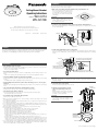
1
Installations
Be sure to read "Precautions" before installation. It is recommended to read them while referring the
operating instructions of the camera together.
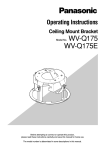
Ceiling Mount Bracket
Operating Instructions
WV-Q174
WV-Q174E
Model No.
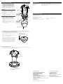
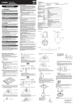
1. Make a hole of 160 mm {6-5/16 inches} diameter using a specialized tool, etc.
When it is impossible to make a precise hole
since no specialized tool is at hand or when
it is impossible to use it because of the location, trace the hole shape using the provided template.
g
m s}
e
0m
ø16 6 inch
1
/
5
{6-
ilin
Ce
Important:
• Make a hole precisely. When the opened
hole is bigger or deformed too much, the
ceiling mount bracket cannot be stuck on
the ceiling board securely.
2. Position two of the spring hooks of the camera as shown in the illustration below.
When the ceiling mount bracket is installed after positioning them in the opposite side, they may
become hard to pull out.
Before attempting to connect or operate this product,
please read these instructions carefully and save this manual for future use.
The model number is abbreviated in some descriptions in this manual.
Ns0810-3012
3TR006706DZA
Printed in China
Main body
←
Move the hook head downward.
Spring hook
Features
This ceiling embedded bracket is exclusively designed to mount a color CCTV camera or a network
camera. Refer to the catalog or the operating instructions of the camera for supported cameras.
This bracket is an embedded type to reduce the exposed portion of the camera body.
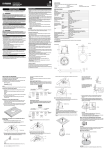
3. Fix the ceiling mount bracket onto the ceiling board.
Loosen the clamping screws until the length between the clamp plates becomes wider that the
thickness of the ceiling board, and then clamp the ceiling board by tightening the clamping
screws.
Triangle mark
Main body
* The "Panasonic" logo on the camera should
be located on the side of this triangle mark.
Precautions
• Refer installation work to the dealer.
Installation work requires technique and experiences. Failure to observe this may cause fire,
electric shock, injury, or damage to the product.
• Be sure to consult the dealer.
Clamp plates
* Clamping screw
* Recommended tightening torque: 0.58 N·m {0.43 lbf·ft}
• Use only the specified camera.
Failure to observe this may cause a fall of an inappropriate camera resulting in injury or accidents.
• Refer to the catalog or the operating instructions of the camera for supported cameras.
• Select an installation area that can support the total weight.
If a selected area is too weak to support the total weight, a fall of the product may occur resulting
in injury.
• Installation work shall be started after sufficient reinforcement.
• Avoid installing this bracket in the locations where salt damage occurs or corrosive gas is
produced.
Otherwise, the mounting portions will deteriorate and accidents such as a fall of the camera may
occur.
• The screws and fixation mechanisms shall be tightened securely.
Failure to observe this may cause a fall of the camera resulting in injury.
• Periodic inspections shall be conducted.
Rust on the metal parts or screws may cause a fall of the product resulting in injury.
• Consult the dealer for the inspections.
• Do not rub the edges of metal parts with your hand.
Failure to observe this may cause injury.
• Make sure that the installation area is strong enough to hold the total weight of the camera
assembly before installation.
• The ceiling mount bracket can be installed only when there is a space whose height is 70 mm or
more above a ceiling board.
• The ceiling mount bracket can be installed on a ceiling board whose thickness is 30 mm or less.
• The camera and the ceiling mount bracket should be fixed using the provided fixing screws, and
make sure that the both of them are fixed firmly.
• When the ceiling mount bracket is not necessary anymore, remove from the ceiling.
• Avoid installing in the following locations.
• Locations where it may get wet from rain or water splash (not only outdoor)
• Locations where a chemical agent is used such as a swimming pool
• Locations subject to steam and oil smoke such as a kitchen
• Locations where radiation or x-ray emissions are produced
• Locations where it may be damaged by briny air such as seashores
• Locations where the temperature is not within the ambient temperature of the camera in use
and this product
• Locations subject to vibrations (This product is not designed for on-vehicle use.)
• Locations where the temperature may rapidly change such as the peripheral areas of the air
outlets of air conditioners or doors facing outside. (In case of installing the camera in such
locations, the dome cover may become foggy or condensation may be caused on the cover.)
• The screws and bolts must be tightened with an appropriate tightening torque according to the
material and strength of the installation area. After tightening the screws or bolts, perform visual
check to ensure tightening is enough and there is no backlash.
Clamp the
ceiling board.
Maximum thickness of the
ceiling board is 30 mm
{1-3/16 inches} for installation.
Important:
• When the ceiling board is the plasterboard, make sure that no crack was made on the ceiling
board by clamping.
4. Connect the cables to the camera.
Refer to the operating instructions of the camera.
Main body
Triangle mark
5-1. When the four mounting holes, fix the
camera using four fixing screws (accessory).
Before fixing the camera, make sure that the
direction marker for installation on the camera body is correctly positioned.
Important:
• This triangle mark and the arrow tip (gTOP)
of the direction marker for installation on the
camera body should be located on the
opposite sides.
Camera
body
Dome cover
Fixing screw
(standard accessory)
Recommended
tightening torque:
1.57 N·m {1.16 lbf·ft}
Dome cover fixing screw
(To be continued to the reverse page)
Installations (continued)
Specifications
5-2. When the two mounting holes, fix the
two adjustment plates using four fixing
screws (accessory). And fix the camera
using two fixing screws (accessory).
Before fixing the camera, make sure that the
direction marker for installation on the camera body is correctly positioned.
Important:
• This triangle mark and the arrow tip (gTOP)
of the direction marker for installation on the
camera body should be located on the
opposite sides.
• Do not pass the cables through the hole of
the main body.
• Take care so that the cables do not touch
the edges of the main body.
6. Adjust the angular field of view and
attach the dome cover to the camera.
(Refer to the operating instructions of the
camera.)
q Adjust the angular field of view and the
focus.
w Attach the dome cover to the camera.
e Fix the dome cover using the dome
cover fixing screw.
Main body
Triangle mark
Ambient temperature:
Dimensions:
Mass:
–10 °C to +50 °C {14°F to 122°F}
ø186 mm {7-5/16 inches} embedding depth 55 mm {2-5/32 inches}
Approx. 310 g {0.68 lbs}
Adjustment
plate
Standard Accessories
Fixing screw
(standard accessory)
Recommended
tightening torque:
1.57 N·m {1.16 lbf·ft}
Operating instructions (this document)................ 1 pc.
AF button push tool ............................................ 1 pc.
Camera
body
The following are for installation.
Fixing screw (M4 x 8) ........................................... 8 pcs. (incl. 2 spare screws)
Adjustment plate ................................................. 2 pcs.
Template (for tracing the hole shape) .................. 1 sheet
Dome cover
Fixing screw
(standard accessory)
Recommended
tightening torque:
1.57 N·m {1.16 lbf·ft}
Dome cover fixing screw
7. According to your need, set the auto focus adjustment. (This procedure is required only
for a camera that has the auto focus function.)
Auto focus adjustment becomes available by pushing the AF button.
Do the following to use the auto focus function.
Refer to the operating instructions of the
camera for further information.
Auto focus adjustment becomes available
by pushing the AF button with the provided
AF button push tool even after mounting the
dome cover. In such a case, the direction of
the camera and the presence of the object
should be checked beforehand because
visual check is not available on the monitor.
Push the AF button with the
provided AF button push tool.
"LOCK" position
AF button
push tool
8. Attach the decorative cover.
Pull out both the spring hooks and attach the hooks to the decorative cover. Make sure that the
cover is attached to the ceiling with no space between them.
Camera
Spring hook (x2)
Decorative cover
* Match the "Panasonic" logos on the cover
and on the camera.
For U.S. and Canada:
Panasonic System Communications
Company of North America,
Unit of Panasonic Corporation
of North America
www.panasonic.com/business/
For customer support, call 1.800.528.6747
Three Panasonic Way, Secaucus, New Jersey 07094 U.S.A.
Panasonic Canada Inc.
5770 Ambler Drive, Mississauga, Ontario, L4W 2T3 Canada
(905)624-5010
www.panasonic.ca
© Panasonic System Networks Co., Ltd. 2012
For Europe and other countries:
http://panasonic.net
Importer's name and address to follow EU rules:
Panasonic Testing Centre
Panasonic Marketing Europe GmbH
Winsbergring 15, 22525 Hamburg F.R.Germany