1
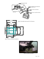
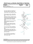
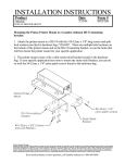
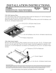
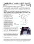
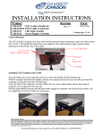
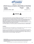
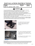
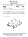
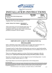
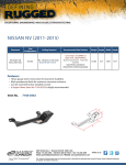
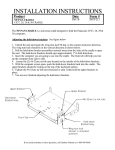
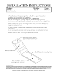
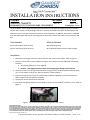
INSTALLATION INSTRUCTIONS
Product
Revision
7160-0312, 7160-0373
VISOR MOUNT,2 UNIT,SINGLE SIDE ATTACHMENT
Rev.D
Form
INST-513
Printing Spec: PS-001
The Visor Mount, 2 Unit, Single Side Attachment provides the user with the capability to secure a mobile camera and a monitor to the passenger side visor. Each system includes two Max3 all axis knuckles that allow the user to orient the monitor and camera in several positions. In addition, the system is equipped with two rubber pads and several mounting holes to ensure the camera and monitor are held secure and firm. Tools Needed Material Needed
5/64‐in Hex wrench (Allen wrench) #10 Self drilling screw 3/16‐in Hex wrench (Allen wrench) #8 x 1.00 sheet metal screw for 2010+ Charger
Installation 1. Remove the passenger side visor retainer clip near the center of the vehicle. Refer to figure 1. 2. Secure the Visor Mount to the headliner using the visor retainer and two additional self tapping fasteners. a. Self tapping fasteners are not supplied. b. Caution: Self tapping fasteners that are too long may go through roof of vehicle. 3. Secure the camera to the front camera bracket using (2) ¼‐20 x .50 socket button head cap screw, (2) ¼‐in lock washer, and (4) ¼‐in nylon flat washers. Refer to figure 2. 4. Secure the monitor to the monitor bracket using hardware supplied by monitor manufacturer. Refer to figure 3 for hole patterns available. 5. Position the camera and monitor as desired. 6. Insert two and tighten all #10‐32 socket head set screws to lock the Max3 knuckles in place. Refer to figure 2. Figure 1. Secure Visor Mount with passenger side visor retainer.
Product Mounting Disclaimer
Gamber-Johnson is not liable under any theory of contract or tort law for any loss, damage, personal injury, special, incidental or consequential damages for personal injury or other damage
of any nature arising directly or indirectly as a result of the improper installation or use of its products in vehicle or any other application. In order to safely install and use Gamber-Johnson
products full consideration of vehicle occupants, vehicle systems (i.e., the location of fuel lines, brakes lines, electrical, drive train or other systems), air-bags and other safety equipment is
required. Gamber-Johnson specifically disclaims any responsibility for the improper use or installation of its products not consistent with the original vehicle manufactures specifications
and recommendations, Gamber-Johnson product instruction sheets, or workmanship standards as endorsed through the Gamber-Johnson Certified Installer Program.
© copyright 2011 Gamber-Johnson, LLC
If you need assistance or have questions, call Gamber-Johnson at 1-800-456-6868
Sheet 1 of 2
#10‐32 socket head set screw
2 X 1/4‐20 x .50 socket button head cap screw
2 X 1/4‐in lock washer
#10‐32 socket head set screw
4 X 1/4‐in nylon flat washer
1 29/32
1 1/2
Figure 2: Assemble camera with 1/4‐in fasteners
15/16 q
1 9/16
1 3/16
1 11/32
Figure 3: Monitor bracket hole patterns
Figure 4: Installed Visor Mount
Sheet 2 of 2