1
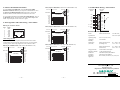
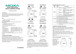
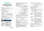
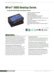
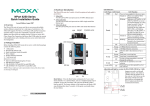
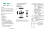
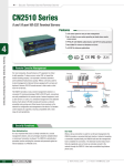
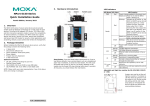
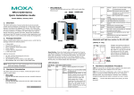
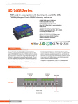
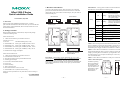
3. Hardware Introduction
NPort 5200-P Series
Quick Installation Guide
As shown in the following figures, NPort 5210-P has two 8-pin RJ45
ports, both for the RS-232 interface, NPort 5230-P has one 10-terminal
terminal block, with 5 pins used for one RS-232 port, and 5 pins used for
one RS-422/485 port.
LED Indicators—The top panels of NPort 5210-P/5230-P have four
LED indicators, as described in the following table.
LED Name LED Color
red
NPort 5210-P
NPort 5230-P
Second Edition, July 2006
Ready
green
1. Overview
Welcome to the programmable NPort 5200-P series, a compact
palm-sized data communication device that allows you to control RS-232
(NPort 5210-P) or RS-232/422/485 (NPort 5230-P) serial devices over a
TCP/IP-based Ethernet.
RJ45 10/100 Mbps
Ethernet port
V-
V+
12-48V
2. Package Checklist
RESET
10/100M
Ethernet
Ready
Before installing the NPort 5210-P/5230-P, verify that the package
contains the following items:
Link
Terminal Block
Power input
Reset button
V-
DIN-Rail
screw hole
V+
RESET
12-48V
off
orange
10/100M
Ethernet
Link
Ready
Link
P1
P1
P2
P2
green
off
orange
5230-P
5210
5210-P
NPort 5210-P/5230-P
Industrial RS-232/422/485 Device Server
Industrial RS-232 Device Server
y 1 NPort 5210-P/5230-P 2-port Serial Device Server
P1, P2
green
off
Optional Accessories
GND
R-/D-
T+
T-
y CBL-RJ45M25-150 RJ45 (8-pin) to DB25 (M) cable, 150 cm
y CBL-RJ45F25-150
RJ45 (8-pin) to DB25 (F) cable, 150 cm
y DIN-Rail Power Supply and Adaptor
NPort 5210-P-ST/5230-P-ST
y 1 NPort 5210-P/5230-P 2-port Serial Device Server
y Documentation & Software CD
y NPort 5210-P/5230-P Series Quick Installation Guide
y Switching power adapter
y Power Jack to Terminal Block Cable
y Power Cord
y Product Warranty
y Turbo C Linense Card
y RJ45 to RJ45 Ethernet cross-over cable
y CBL-RJ45M9-150 x 2 (NPort 5210-P-ST Only)
RS-232 & RS-422/485
Terminal Block
RJ45 (8-pin) serial ports
Reset Button—Press the Reset button continuously for 5 sec to load
factory defaults: Use a pointed object, such as a straightened paper clip or
toothpick, to press the reset button. This will cause the Ready LED to
blink on and off. The factory defaults will be loaded once the Ready LED
stops blinking (after about 5 seconds). At this point, you should release
the reset button.
Notify your sales representative if any of the above items is missing or
damaged.
100 Mbps Ethernet connection.
Ethernet cable is disconnected, or has a
short.
Serial port is receiving data.
Serial port is transmitting data.
No data is being transmitted or received
through the serial port.
4. Hardware Installation Procedure
P2 RS-485/422
R+/D+
RJ45 (8-pin) to DB9 (F) cable, 150 cm
P1 RS-232
GND
y CBL-RJ45F9-150
Wallmount
screw hole
CTS
RJ45 (8-pin) to DB9 (M) cable, 150 cm
Port 2
RS-232
Tx
y CBL-RJ45M9-150
Port 1
RS-232
Rx
DIN-Rail Mounting Kit (35 mm)
RTS
y DK-35A
LED Function
Power is on and NPort 5200-P
series is booting up.
Blinking:
Indicates an IP conflict, or
DHCP or BOOTP server did
not respond properly.
Steady on: Power is on and NPort 5200-P
series is functioning normally.
Blinking:
The device server has been
located by Administrator’s
Location function
Power is off, or power error condition
exists.
10 Mbps Ethernet connection.
Steady on:
STEP 1: After removing NPort 5210-P/5230-P from the box, the first
thing you should do is connect the power adaptor. Connect the 12-30
VDC power line with NPort 5210-P/5230-P’s terminal block, or connect
the DIN-Rail power supply with NPort 5210-P/5230-P’s terminal block.
STEP 2: Connect NPort 5210-P/5230-P to a network. Use a standard
straight-through Ethernet cable to connect to a Hub or Switch. When
setting up or testing NPort 5210-P/5230-P, you might find it convenient
to connect directly to your computer’s Ethernet port. In this case, use a
cross-over Ethernet cable.
STEP 3: Connect NPort 5210-P/5230-P’s serial port to a serial device.
STEP 4: Placement Options
Wall Mount
In addition to placing
NPort 5210-P/5230-P
on a desktop or other
horizontal surface, you
may also make use of
the DIN-Rail or Wall
Mount options, as
illustrated here.
V-
V+
RESET
12-30V
Ready
Link
P1
P2
5210-P
5210
Industrial RS-232 Device Server
Port 1
RS-232
Port 2
RS-232
P/N:1802052003000
—1—
—2—
10/100M
Ethernet
—3—
DIN-Rail
5. Software Installation Information
To install NPort PCG SDK2 Suite, insert the NPort PCG SDK2
Document & Software CD into your computer’s CD-ROM drive. Once
the NPort PCG SDK2 Installation CD window opens, click on the
Installation button, and then follow the instructions on the screen.
RJ45 (8-pin) Connector Pinouts
8-Pin
Signal
1
2
3
4
5
6
7
8
DSR
RTS
GND
TxD
RxD
DCD
CTS
DTR
RJ45 Connector
DB25 Male
Cable Wiring
8 pins
6
4
7
2
3
8
5
20
1
2
3
4
5
6
7
8
RJ45 Connector
DB9 Female
RxD
Tx
DTR
CTS
GND
RxD
TxD
DCD
RTS
DSR
TxD
Rx
CTS
RTS
RTS
CTS
GND
GND
8
Cable Wiring
8 pins
Cable Wiring (RS-232)
Four cables are provided as optional accessories that can be used to
connect NPort 5210-P to RS-232 serial devices. For your convenience,
we show precise cable wiring diagrams for each of the four cables.
DSR
RTS
GND
TxD
RxD
DCD
CTS
DTR
25 pins
4
8
5
2
3
1
7
6
1
2
3
4
5
6
7
8
Rx+
T+
Rx-
T-
Tx+ / Data+
R+/D+
Tx- / Data-
R-/D-
GND
GND
DB9 Male
RS-232
Device
NPort 5210
1
NPort 5230
Signals
25 pins
RJ45 (8-pin) to DB9 Female (Cable Name: CBL-RJ45F9-150)
RJ45 Port
Serial Device
Signals
RS-232
Device
NPort 5210
DSR
RTS
GND
TxD
RxD
DCD
CTS
DTR
DB25
Female
DTR
CTS
GND
RxD
TxD
DCD
RTS
DSR
RJ45 (8-pin) to DB9 Male (Cable Name: CBL-RJ45M9-150)
8. Environmental Specifications
Power
requirements
NPort 5210-P/5230-P:
Operating temp.
Operating
humidity
Dimensions
(W×D×H)
0 to 55◦C (32 to 131◦F)
5 to 95% RH
RJ45 (8-pin) to DB25 Female (Cable Name: CBL-RJ45F25-150)
RJ45 Port
RJ45 Port
RJ45 Connector
DB25 Female
RS-232
Device
NPort 5210
Cable Wiring
8 pins
DSR
RTS
GND
TxD
RxD
DCD
CTS
DTR
DB25
Male
1
2
3
4
5
6
7
8
25 pins
20
5
7
3
2
8
4
6
DTR
CTS
GND
RxD
TxD
DCD
RTS
DSR
RJ45 Connector
DB9 Male
Cable Wiring
8 pins
DSR
RTS
GND
TxD
RxD
DCD
CTS
DTR
DB9 Female
RS-232
Device
NPort 5210
1
2
3
4
5
6
7
8
25 pins
6
7
5
4
3
1
8
4
P2 RS-485/422
6. Pin Assignments and Cable Wiring—NPort 5210-P
RJ45 Port
7. Terminal Block Wiring—NPort 5230-P
P1 RS-232
To view detailed information about NPort PCG SDK Manager, click on
the Documents button, and then select “NPort PCG SKD2 Programmer
Guide” to open the pdf version of this user’s guide.
RJ45 (8-pin) to DB25 Male (Cable Name: CBL-RJ45M25-150)
DTR
CTS
GND
RxD
TxD
DCD
RTS
DSR
Surge protection
Magnetic isolation
Power line
protection
Regulatory
approvals
12 to 48 VDC, 305
mA at 12V (max.)
NPort 5210-P/5230-P
(including ears)
90 × 100.4 × 22 mm
3.54 × 3.95 × 0.87 in
NPort 5210-P/5230-P
(without ears)
67 × 100.4 × 22 mm
2.64 × 3.95 × 0.87 in
15 KV ESD for serial ports
1.5 KV for Ethernet port
4 KV Burst (EFT), EN61000-4-4
2 KV Surge, EN61000-4-5
FCC Class A, CE Class A, UL, CUL, TÜV
Copyright © 2006
Moxa Technologies Co., Ltd.
All rights reserved.
Reproduction without permission is prohibited.
Tel: +886-2-8919-1230
Fax: +886-2-8919-1231
—4—
—5—
www.moxa.com
[email protected]
—6—