1
EP4650/EP5550 User
Guide
Copyright © 9 May 2013 by Planar Systems, Inc. All rights reserved.
Contents of this publication may not be reproduced in any form without permission of Planar
Systems, Inc.
Trademark Credits
Windows™ is a trademark of Microsoft Corp.
All other companies are trademarks or registered trademarks of their respective companies.
Disclaimer
The information contained in this document is subject to change without notice. Planar
Systems, Inc. makes no warranty of any kind with regard to this material. While every
precaution has been taken in the preparation of this manual, the Company shall not be liable
for errors or omissions contained herein or for incidental or consequential damages in
connection with the furnishing, performance, or use of this material.
Warranty and Service Plans
Planar warranty and service plans will help you maximize your investment by providing great
support, display uptime, and performance optimization. From post-sale technical support to
a full suite of depot services, our services are performed by trained Planar employees. When
you purchase a Planar product, you get more than a display, you get the service and support
you need to maximize your investment. To find the latest warranty and service information
regarding your Planar product, please visit http://www.planarcontrolroom.com/support
RoHS Compliance Statement
The EP4650/EP5550s are fully RoHS compliant.
Part Number: 020-1228-01A
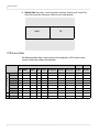
Table of Contents
EP4650/EP5550 User Guide . . . . . . . . . . . . . . . . . . . . . . . . . . . . . . . . . . . . . . . . . . . . . . . . . . . . . . . . . . . . . . . . . . . . . . . . i
Introduction . . . . . . . . . . . . . . . . . . . . . . . . . . . . . . . . . . . . . . . . . . . . . . . . . . . . . . . . . . . . . . . . . . . . . . . . . . . . . . . . . . . . . . .1
Safety Information . . . . . . . . . . . . . . . . . . . . . . . . . . . . . . . . . . . . . . . . . . . . . . . . . . . . . . . . . . . . . . . . . . . . . . . . . . . . . . .2
Safety Precautions. . . . . . . . . . . . . . . . . . . . . . . . . . . . . . . . . . . . . . . . . . . . . . . . . . . . . . . . . . . . . . . . . . . . . . . . . . . . . . . .2
Recommended Usage . . . . . . . . . . . . . . . . . . . . . . . . . . . . . . . . . . . . . . . . . . . . . . . . . . . . . . . . . . . . . . . . . . . . . . . . . . . .4
VESA Mounts, General Description . . . . . . . . . . . . . . . . . . . . . . . . . . . . . . . . . . . . . . . . . . . . . . . . . . . . . . . . . . . . . . . .6
Cleaning the EP4650/EP5550 . . . . . . . . . . . . . . . . . . . . . . . . . . . . . . . . . . . . . . . . . . . . . . . . . . . . . . . . . . . . . . . . . . . . .7
Package Contents . . . . . . . . . . . . . . . . . . . . . . . . . . . . . . . . . . . . . . . . . . . . . . . . . . . . . . . . . . . . . . . . . . . . . . . . . . . . . . . . . .8
Unpacking the EP4650/EP5550 . . . . . . . . . . . . . . . . . . . . . . . . . . . . . . . . . . . . . . . . . . . . . . . . . . . . . . . . . . . . . . . . . . .8
Dimensions . . . . . . . . . . . . . . . . . . . . . . . . . . . . . . . . . . . . . . . . . . . . . . . . . . . . . . . . . . . . . . . . . . . . . . . . . . . . . . . . . . . . . . 11
EP4560 - Front . . . . . . . . . . . . . . . . . . . . . . . . . . . . . . . . . . . . . . . . . . . . . . . . . . . . . . . . . . . . . . . . . . . . . . . . . . . . . . . . . 11
EP4560 - Rear . . . . . . . . . . . . . . . . . . . . . . . . . . . . . . . . . . . . . . . . . . . . . . . . . . . . . . . . . . . . . . . . . . . . . . . . . . . . . . . . . . 12
EP4560 - Side. . . . . . . . . . . . . . . . . . . . . . . . . . . . . . . . . . . . . . . . . . . . . . . . . . . . . . . . . . . . . . . . . . . . . . . . . . . . . . . . . . . 13
Standard Inputs . . . . . . . . . . . . . . . . . . . . . . . . . . . . . . . . . . . . . . . . . . . . . . . . . . . . . . . . . . . . . . . . . . . . . . . . . . . . . . . . 13
Optional HD-SDI/VW Inputs . . . . . . . . . . . . . . . . . . . . . . . . . . . . . . . . . . . . . . . . . . . . . . . . . . . . . . . . . . . . . . . . . . . . 14
EP5550 - Front . . . . . . . . . . . . . . . . . . . . . . . . . . . . . . . . . . . . . . . . . . . . . . . . . . . . . . . . . . . . . . . . . . . . . . . . . . . . . . . . . 14
EP5550 - Rear . . . . . . . . . . . . . . . . . . . . . . . . . . . . . . . . . . . . . . . . . . . . . . . . . . . . . . . . . . . . . . . . . . . . . . . . . . . . . . . . . . 15
EP5550 - Side. . . . . . . . . . . . . . . . . . . . . . . . . . . . . . . . . . . . . . . . . . . . . . . . . . . . . . . . . . . . . . . . . . . . . . . . . . . . . . . . . . . 16
Installing an EP4650/EP5550 . . . . . . . . . . . . . . . . . . . . . . . . . . . . . . . . . . . . . . . . . . . . . . . . . . . . . . . . . . . . . . . . . . . . 17
Before You Begin . . . . . . . . . . . . . . . . . . . . . . . . . . . . . . . . . . . . . . . . . . . . . . . . . . . . . . . . . . . . . . . . . . . . . . . . . . . . . . . 17
Power Input. . . . . . . . . . . . . . . . . . . . . . . . . . . . . . . . . . . . . . . . . . . . . . . . . . . . . . . . . . . . . . . . . . . . . . . . . . . . . . . . . . . . 18
Operating the EP4560/EP5550. . . . . . . . . . . . . . . . . . . . . . . . . . . . . . . . . . . . . . . . . . . . . . . . . . . . . . . . . . . . . . . . . . . 19
EP4650/EP5550 User Manual
i
Table of Contents
OSD Keypad . . . . . . . . . . . . . . . . . . . . . . . . . . . . . . . . . . . . . . . . . . . . . . . . . . . . . . . . . . . . . . . . . . . . . . . . . . . . . . . . . . . .19
Remote Control Receiver . . . . . . . . . . . . . . . . . . . . . . . . . . . . . . . . . . . . . . . . . . . . . . . . . . . . . . . . . . . . . . . . . . . . . . . .20
LED Indicators . . . . . . . . . . . . . . . . . . . . . . . . . . . . . . . . . . . . . . . . . . . . . . . . . . . . . . . . . . . . . . . . . . . . . . . . . . . . . . . . . .21
Using the Display in Portrait Mode . . . . . . . . . . . . . . . . . . . . . . . . . . . . . . . . . . . . . . . . . . . . . . . . . . . . . . . . . . . . . . .21
Using the Remote Control . . . . . . . . . . . . . . . . . . . . . . . . . . . . . . . . . . . . . . . . . . . . . . . . . . . . . . . . . . . . . . . . . . . . . . .22
Turning the EP4650/EP5550 On. . . . . . . . . . . . . . . . . . . . . . . . . . . . . . . . . . . . . . . . . . . . . . . . . . . . . . . . . . . . . . . . . .25
Turning the EP4650/EP5550 Off . . . . . . . . . . . . . . . . . . . . . . . . . . . . . . . . . . . . . . . . . . . . . . . . . . . . . . . . . . . . . . . . .26
Adjusting the Volume . . . . . . . . . . . . . . . . . . . . . . . . . . . . . . . . . . . . . . . . . . . . . . . . . . . . . . . . . . . . . . . . . . . . . . . . . . .26
Selecting the Input Source . . . . . . . . . . . . . . . . . . . . . . . . . . . . . . . . . . . . . . . . . . . . . . . . . . . . . . . . . . . . . . . . . . . . . .27
PIP Mode . . . . . . . . . . . . . . . . . . . . . . . . . . . . . . . . . . . . . . . . . . . . . . . . . . . . . . . . . . . . . . . . . . . . . . . . . . . . . . . . . . . . . . .28
OSD Menu Functions. . . . . . . . . . . . . . . . . . . . . . . . . . . . . . . . . . . . . . . . . . . . . . . . . . . . . . . . . . . . . . . . . . . . . . . . . . . .31
OSD Menus . . . . . . . . . . . . . . . . . . . . . . . . . . . . . . . . . . . . . . . . . . . . . . . . . . . . . . . . . . . . . . . . . . . . . . . . . . . . . . . . . . . . .36
Navigating Through the Menus. . . . . . . . . . . . . . . . . . . . . . . . . . . . . . . . . . . . . . . . . . . . . . . . . . . . . . . . . . . . . . . . . .40
Default Settings . . . . . . . . . . . . . . . . . . . . . . . . . . . . . . . . . . . . . . . . . . . . . . . . . . . . . . . . . . . . . . . . . . . . . . . . . . . . . . . . .58
LAN Control. . . . . . . . . . . . . . . . . . . . . . . . . . . . . . . . . . . . . . . . . . . . . . . . . . . . . . . . . . . . . . . . . . . . . . . . . . . . . . . . . . . . . . .59
Supported Operating Systems. . . . . . . . . . . . . . . . . . . . . . . . . . . . . . . . . . . . . . . . . . . . . . . . . . . . . . . . . . . . . . . . . . .59
Installation. . . . . . . . . . . . . . . . . . . . . . . . . . . . . . . . . . . . . . . . . . . . . . . . . . . . . . . . . . . . . . . . . . . . . . . . . . . . . . . . . . . . . .59
Configuring VCOM . . . . . . . . . . . . . . . . . . . . . . . . . . . . . . . . . . . . . . . . . . . . . . . . . . . . . . . . . . . . . . . . . . . . . . . . . . . . . .63
Function Descriptions . . . . . . . . . . . . . . . . . . . . . . . . . . . . . . . . . . . . . . . . . . . . . . . . . . . . . . . . . . . . . . . . . . . . . . . . . . .65
Setting Up Email Alerts . . . . . . . . . . . . . . . . . . . . . . . . . . . . . . . . . . . . . . . . . . . . . . . . . . . . . . . . . . . . . . . . . . . . . . . . . . .69
Login . . . . . . . . . . . . . . . . . . . . . . . . . . . . . . . . . . . . . . . . . . . . . . . . . . . . . . . . . . . . . . . . . . . . . . . . . . . . . . . . . . . . . . . . . . .69
Administrator . . . . . . . . . . . . . . . . . . . . . . . . . . . . . . . . . . . . . . . . . . . . . . . . . . . . . . . . . . . . . . . . . . . . . . . . . . . . . . . . . . .71
TCP Mode, UDP Mode and UART. . . . . . . . . . . . . . . . . . . . . . . . . . . . . . . . . . . . . . . . . . . . . . . . . . . . . . . . . . . . . . . . .74
SMTP . . . . . . . . . . . . . . . . . . . . . . . . . . . . . . . . . . . . . . . . . . . . . . . . . . . . . . . . . . . . . . . . . . . . . . . . . . . . . . . . . . . . . . . . . . .74
Reset Device . . . . . . . . . . . . . . . . . . . . . . . . . . . . . . . . . . . . . . . . . . . . . . . . . . . . . . . . . . . . . . . . . . . . . . . . . . . . . . . . . . . .75
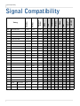
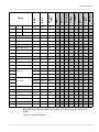
Signal Compatibility . . . . . . . . . . . . . . . . . . . . . . . . . . . . . . . . . . . . . . . . . . . . . . . . . . . . . . . . . . . . . . . . . . . . . . . . . . . . . .76
ii
EP4650/EP5550 User Manual
Table of Contents
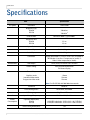
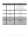
Specifications . . . . . . . . . . . . . . . . . . . . . . . . . . . . . . . . . . . . . . . . . . . . . . . . . . . . . . . . . . . . . . . . . . . . . . . . . . . . . . . . . . . . 78
Troubleshooting . . . . . . . . . . . . . . . . . . . . . . . . . . . . . . . . . . . . . . . . . . . . . . . . . . . . . . . . . . . . . . . . . . . . . . . . . . . . . . . . . 80
Accessing Planar’s Technical Support Website . . . . . . . . . . . . . . . . . . . . . . . . . . . . . . . . . . . . . . . . . . . . . . . . . . . 81
Downloading Additional Documentation and Firmware . . . . . . . . . . . . . . . . . . . . . . . . . . . . . . . . . . . . . . . . . 81
Downloading Utility Software. . . . . . . . . . . . . . . . . . . . . . . . . . . . . . . . . . . . . . . . . . . . . . . . . . . . . . . . . . . . . . . . . . . 82
EP4650/EP5550 User Manual
iii
Table of Contents
iv
EP4650/EP5550 User Manual
Introduction
The EP4650/EP5550 is a 46” or 55” diagonal edge-lit LED LCD display that can be wall
mounted, ceiling mounted or mounted on a stand. The display can be portrait or
landscape.
The EP4650 and EP5550 are ultra slim and have an aspect ratio of 1.77 (16:9). The
EP4650/EP5550 have a native HD (1920 x 1080) resolution and both accept a wide
range of input pictures from VGA to 1080p.
Additional features of the Planar EP4650 and EP5550 include ambient light control, a
wide range of source connectivity, and display control through LAN or RS232. The EP
series displays also provide superior energy efficiency in a lightweight design.
Caution: This manual is intended for use by qualified service persons and end users with
experience installing LCD displays.
EP4650/EP5550 User Manual
1
Safety Information
Safety Information
Before using the EP4650/EP5550, please read this manual thoroughly to help protect
against damage to property, and to ensure personnel safety.
• Be sure to observe the following instructions.
• For your safety, be sure to observe ALL the warnings detailed in this manual.
• For installation or adjustment, please follow this manual’s instructions, and refer
all servicing to qualified service personnel.
Safety Precautions
• If water is spilled or objects are dropped inside the ep46L/ep55L, remove
the power plug from the outlet immediately. Failure to do so may result in
fire or electrical shock. Contact your dealer for inspection.
• If the EP4650/EP5550 is dropped or the chassis is damaged, remove the
power plug from the outlet immediately. Failure to do so may result in fire or
electrical shock. Contact your dealer for inspection.
WARNING! Wall mounts must be secure.
• If the display is hung on a wall, the wall must be strong enough to hold it.
Simply mounting it to wallboard or wall paneling won’t be adequate or safe.
Caution: The screen could be damaged by heavy pressure.
• Slight pressure on the LCD will cause distortion of the image. Heavier
pressure will cause permanent damage. Displays should be mounted where
viewers cannot touch the screen or insert small objects in the openings that will
create hazards by contacting bare conductive parts.
Caution: The front polarizer is soft and subject to scratches from sharp objects.
• The polarizer is a thin sheet of film laminated to the outside layer of glass
on the LCD screen. Take care when handling items near the screen.
• If the power cord or plug is damaged or becomes hot, turn off the main
power switch of the display. Make sure the power plug has cooled down
and remove the power plug from the outlet. If the EP4650/EP5550 is still used
in this condition, it may cause a fire or an electrical shock. Contact your dealer
for a replacement.
2
EP4650/EP5550 User Manual
Important Safety Instructions
Important Safety Instructions
1 Read these instructions.
2 Keep these instructions.
3 Heed all warnings.
4 Follow all instructions.
5 Do not use the EP4650/EP5550 near water.
6 Clean the LCD screens with an LCD screen cleaner or LCD wipes.
7 Do not install near any heat sources such as radiators, heat registers, stoves or
other apparatus (including amplifiers) that produce heat.
8 Do not defeat the safety purpose of the polarized or grounding type plug. A
polarized plug has two blades with one wider than the other. A grounding type
plug has two blades and a third grounding prong. The wide blade or the third
prong is provided for your safety. When the provided plug does not fit into your
outlet, consult an electrician for the replacement of the obsolete outlet.
9 Protect the power cord from being walked on or pinched, particularly at plugs,
convenience receptacles and the point where they exit from any of the
EP4650/EP5550 displays.
10 Only use the attachments/accessories specified by the manufacturer.
11 Unplug all displays during lightning storms or when unused for long periods of
time.
12 You must follow all National Electrical Code regulations. In addition, be aware of
local codes and ordinances when installing your system.
13 Refer all servicing to qualified service personnel. Servicing is required when any
of the displays have been damaged in any way. For example, if the AC power cord
or plug is damaged, liquid has been spilled or objects have fallen into a display,
the displays have been exposed to rain or moisture, do not operate normally or
have been dropped.
14 Keep the packing material in case the equipment should ever need to be
shipped.
15 Wall mounts must be secure. The wall must be strong enough to hold all
EP4650/EP5550s, brackets and cables.
EP4650/EP5550 User Manual
3
Recommended Usage
16 Slight pressure on the LCD will cause distortion of the image. Heavier pressure
will cause permanent damage. Displays should be mounted where viewers
cannot touch the screen or insert small objects in the openings that will create
hazards by contacting bare conductive parts.
17 The front polarizer is soft and subject to scratches from sharp objects. The
polarizer is a thin sheet of film laminated to the outside layer of glass on the LCD
screen. Take care when handling items near the screen.
Recommended Usage
In order to get the most out of your LCD, use the following recommended guidelines
to optimize the display.
Burn-In Versus Temporary Image Retention
Burn-in causes the screen to retain an image essentially forever, with little or no way
to correct the problem. Under normal use, an LCD will not experience burn-in, as
plasma displays do, nor will it retain images in any way.
Normal use of an LCD is defined as displaying continuously changing video patterns
or images. However, LCDs can experience temporary image retention when
recommended usage guidelines are not followed.
What is Temporary Image Retention?
Temporary image retention (TIR) can occur when a static image is displayed
continuously for extended periods of time (12 hours or longer). An electrical charge
differential may build up between the electrodes of the liquid crystal, which causes a
negative-color video image (color-inverted and brightness-inverted version of the
previous image) to be retained when a new image is displayed. This behavior is true
for any LCD device from any LCD manufacturer.
TIR is not covered under warranty. See standard warranty terms and conditions for
details. Here are some guidelines to help you avoid TIR:
• Use the LCD to show a screen saver, moving images or still pictures that change
regularly. When using high-contrast images, reposition the images frequently.
• Turn off the LCD when it is not in use. To use your source computer’s Power
Options Properties, set up your computer to turn off the display when not in
use.
Caution: For optimal performance, we suggest turning off the backlight power on the
EP4650/EP5550 for six hours per day.
4
EP4650/EP5550 User Manual
European Union Disposal Information
European Union Disposal Information
Français
English
■ Disposal of old Electrical & Electronic Equipment (Applicable throughout
the European Union and other European countries with separate collection
programs)
■ Mise au rebut des équipements électriques et électroniques usagés
(Valable dans l’ensemble de l’Union Européenne ainsi que dans les pays
européens disposant de programmes distincts de collecte des déchets)
Deutsch
■ Entsorgung von elektrischen & elektronischen Altgeräten (geltend für die
europäische Gemeinschaft und andere europäische Länder mit separaten
Sammelprogrammen)
This symbol found on your product or on its packaging, indicates that
this product should not be treated as household waste when you wish to
dispose of it. Instead, it should be handed over to an applicable collection
point for the recycling of electrical and electronic equipment. By ensuring
this product is disposed of correctly, you will help prevent potential
negative consequences to the environment and human health, which
could otherwise be caused by inappropriate disposal of this product. The
recycling of materials will help to conserve natural resources.
Ce symbole appliqué sur votre produit ou sur son emballage indique
que ce produit ne doit pas être traité comme un déchet ménager lorsque
vous voulez le mettre au rebut. Il doit au contraire être remis à un site
de collecte agréé pour le recyclage des équipements électriques et
électroniques. En veillant à ce que ce produit soit mis au rebut de façon
adéquate, vous contribuerez à prévenir les conséquences potentiellement
négatives sur l’environnement et sur la santé humaine qui risqueraient
de se produire en cas de mise au rebut inappropriée de ce produit. Le
recyclage des matériaux contribuera également à économiser les ressources naturelles.
Dieses Symbol, zu finden auf Ihrem Produkt oder dessen Verpackung,
macht Sie darauf aufmerksam, dass dieses Produkt bei der Entsorgung
nicht als Hausmüll behandelt werden darf. Statt dessen sollte es an eine
Sammelstelle zum Recycling von elektrischen und elektronischen Altgeräten gegeben werden. Helfen Sie mit, potenziell schädliche Einflüsse
auf Umwelt und Gesundheit, die durch eine unsachgemäße Entsorgung
dieses Produktes entstehen können, zu vermeiden und entsorgen Sie
dieses Produkt ordnungsgemäß. Recycling hilft, natürliche Rohstoffe
einzusparen.
This symbol is only valid in the European Union.
If you wish to discard this product, please contact
your local authorities or dealer and ask for the correct method of disposal.
Ce symbole n’est valable que dans l’Union Européenne.
Si vous souhaitez mettre ce produit au rebut, veuillez
prendre contact avec les autorités locales ou avec votre
revendeur et renseignez-vous sur la méthode de mise
au rebut correcte.
Dieses Symbol ist nur innerhalb der europäischen
Gemeinschaft gültig.
Wenn Sie dieses Produkt entsorgen möchten, wenden
Sie sich bitte an Ihre örtliche Behörde und fragen Sie
nach der ordnungsgemäßen Entsorgungsmethode.
Italiano
Español
■ Deshecho de equipos eléctricos y electrónicos (aplicable a la Unión Europea y a otros países europeos con programas de reciclaje independientes)
La presencia de este símbolo en el propio producto o en su material de
embalaje, indica que no se debe tratar como residuo doméstico cuando
desee deshacerse de él. En su lugar, debe entregarlo en el punto limpio
correspondiente de reciclaje de equipos eléctricos y electrónicos. Asegurándose de que este producto se desecha de forma correcta, ayudará
a evitar posibles consecuencias negativas para la conservación del
medioambiente y la salud humana, consecuencias que podrían darse si
se deshace del producto de forma inadecuada. El reciclado de materiales
ayuda a conservar los recursos naturales.
Este símbolo solamente es válido en la Unión
Europea.
Si desea deshacerse de este producto, póngase
en contacto con las autoridades locales o con su
distribuidor y pida información sobre el método de
disposición adecuado.
■ Smaltimento delle attrezzature elettriche ed elettroniche usate (applicabile
in tutta la Comunità Europea ed altri Paesi Europei che applicano
programmi di raccolta differenziata)
Il simbolo trovato sul prodotto, o sulla sua confezione, indica che il
prodotto non può essere trattato come i domestici quando è il momento
di smaltirlo. Al contrario, deve essere consegnato ad un centro di raccolta
specializzato nel riciclaggio di attrezzature elettriche ed elettroniche. Assicurando che il corretto smaltimento di questo prodotto, si aiuterà a prevenire potenziali conseguenze negative sull’ambiente e sulla salute umana,
che possono essere provocate da uno scorretto smaltimento di questa
attrezzatura. I materiali riciclati aiuteranno a conservare le risorse naturali.
Questo simbolo è valido solo nell’Unione Europea.
Per smaltire questo prodotto, mettersi in contatto con
le autorità locali – o con il rivenditore – e chiedere
informazioni sul corretto metodo di smaltimento.
Polski
Português
■ Eliminação de equipamentos eléctricos e electrónicos usados (aplicável
na União Europeia e noutros países europeus com programas próprios de
recolha destes equipamentos)
Este símbolo, colocado no produto ou na respectiva embalagem, indica
que o produto não deve ser tratado como lixo doméstico aquando da sua
eliminação. Em vez disso, deve ser entregue num ponto de recolha de equipamentos eléctricos e electrónicos para posterior reciclagem. Ao garantir
a correcta eliminação deste produto, estará a evitar consequências potencialmente negativas tanto para o ambiente como para a saúde humana. A
reciclagem de materiais ajuda a preservar os recursos naturais.
Este símbolo apenas é válido na União Europeia.
Se quiser eliminar este produto, contacte as entidades locais ou o seu fornecedor para ficar a saber
qual o método de eliminação correcto.
■ Usuwanie zużytego sprzętu elektrycznego i elektronicznego (Dotyczy
krajów Unii Europejskiej i innych krajów europejskich z oddzielnymi
programami zbiórki odpadów)
Obecność tego symbolu na produkcie lub na opakowaniu z produktem
oznacza, że tego produktu nie można wyrzucać razem z odpadkami
domowymi. Należy go przekazać do punktu zbiórki w celu poddania
recyklingowi podzespołów elektrycznych i elektronicznych. Usunięcie tego
produktu w prawidłowy sposób, pomoże w zabezpieczeniu przed negatywnym wpływem odpadów na środowisko i zdrowie ludzi, powodowanym
przez niewłaściwe usuwanie produktu. Przetwarzanie materiałów pomaga
w zachowaniu zasobów naturalnych.
Ten symbol obowiązuje wyłącznie w krajach Unii
Europejskiej.
Informacje dotyczące prawidłowej metody usunięcia
tego produktu, można uzyskać u władz lokalnych lub
u dostawcy.
Suomi
Svenska
■ Avfall av förbrukad elektrisk och elektronisk utrustning (Tillämpbart i
hela Europeiska unionen och andra europeiska länder med separata
samlingsprogram)
Den här symbolen som finns på din product eller på dess förpackning
påvisar att produkten inte ska behandlas som hushållsavfall när du vill
slänga bort den. Istället ska den lämnas över till en lämplig uppsamlingspunkt för återvinning av elektriska och elektroniska utrustningar. Genom att
tillförsäkra att den här produkten återvinns på ett riktigt sätt hjälper du till
med att förhindra möjliga negative konsekvenser för miljön och mänsklig
hälsa. Det kan annars orsakas på grund av olämplig sophantering av den
här produkten. Återvinning av material kommer att hjälpa till att bevara
naturtillgångar.
Den här symbolen är endast giltig inom den
Europeiska unionen.
Om du vill slänga bort den här produkten ska du
kontakta lokala myndigheter eller återförsäljar, och
fråga efter lämplig avfallsmetod.
■ Vanhojen sähkö- ja elektroniikkalaitteiden hävittäminen (Soveltuva kaikkialla Euroopan unionin alueella, sekä muissa Euroopan maissa, joilla on
erilliset keräysohjelmat)
Jos tuotteessa tai sen pakkauksessa on tämä symboli, sitä ei pidä
hävitettäessä käsitellä tavallisena kotitalousjätteenä, vaan se kuuluu toimittaa sähkö- ja elektroniikkalaitteiden kierrätyspisteeseen. Varmistamalla,
että tämä tuote hävitetään asiaankuuluvalla tavalla autat estämään mahdollisia ympäristölle ja ihmisille koituvia negatiivisia seuraamuksia, joita
sen vääränlainen hävittäminen voi aiheuttaa. Materiaalien kierrättäminen
auttaa säilyttämään luonnonvaroja.
Tämä symboli on voimassa ainoastaan Euroopan
unionin alueella.
Jos haluat hävittää tämän tuotteen, ota yhteyttä
paikallisiin viranomaisiin tai jälleenmyyjään ja tiedustele
asiaankuuluvia hävittämistoimenpiteitä.
EP4650/EP5550 User Manual
Nederlands
■ Verwijderen van oude elektrische en elektronische apparatuur (toepasselijk in de volledige Europese Unie en andere Europese landen met
afzonderlijke programma’s voor afvalverzameling)
Dit symbool dat op het product of zijn verpakking is aangebracht, geeft aan
dat dit product niet mag worden behandeld als huishoudelijk afval als u het
wilt wegwerpen. U moet het afgeven bij een specifiek verzamelpunt voor
de recyclage van elektrische en elektronische apparatuur. Door te garanderen dat u dit product op de correcte manier wegwerpt, helpt u potentiële
negatieve gevolgen voor het milieu en de menselijke gezondheid, die
zouden kunnen worden veroorzaakt door een onrechtmatig wegwerpen
van het product, te voorkomen. De recyclage van materialen helpt het
behoud van natuurlijke bronnen.
Dit symbool is alleen geldig in de Europese Unie.
Als u dit product wenst weg te gooien, dient u contact op
te nemen met uw lokale instanties voor details over de
gepaste methode voor afvalverwijdering.
Waste Electrical and Electronic Equipment (WEEE) Directive In the European Union, this label indicates that this product should not be disposed of with household waste. It should be deposited at an appropriate facility to enable recovery and recycling. EEE complies with Directive ‘Regulation on the Restriction of the Use of Certain Hazardous Substances in Electrical and Electronic Equipment’
Waste Electrical and Electronic Equipment (WEEE) Directive In the European Union, this label indicates that this product should not be disposed of with household waste. It should be deposited at an appropriate facility to enable recovery and recycling. EEE complies with Directive ‘Regulation on the Restriction of the Use of Certain Hazardous Substances in Electrical and Electronic Equipment’
Waste Electrical and Electronic Equipment (WEEE) Yönergeleri Avrupa Birliği'nde bu etiket, ürünün ev elektroniği aletleri atıkları ile imha edilemeyeceğini gösterir. Kurtarmak ve geri dönüşümünü sağlamak için uygun şartlarda saklanması gerekir. EEE Yönetmeliğine Uygundur Ve Elektronik Eşyalarda Bazi Zararli Maddelerin Kullaniminin Sinirlandirilmasina Dair Yönetmelik.
Waste Electrical and Electronic Equipment
(WEEE) Yönergeleri Avrupa Birliği'nde bu etiket,
ürünün ev elektroniği aletleri atıkları ile imha
edilemeyeceğini gösterir. Kurtarmak ve geri
dönüşümünü sağlamak için uygun şartlarda
saklanması gerekir. EEE Yönetmeliğine
Uygundur Ve Elektronik Eşyalarda Bazi Zararli
Maddelerin Kullaniminin Sinirlandirilmasina Dair
Yönetmelik.
5
Normal Usage Guidelines
Normal Usage Guidelines
Normal use of the LCD is defined as operating in the open air to prevent heat
buildup, and without direct or indirect heat sources such as lighting fixtures, heating
ducts, or direct sunlight that can cause the modules to experience high operating
temperatures. For all modules, do not block fans or ventilation openings. If the LCD
module will be installed in a recessed area with an LCD surround or enclosure, ensure
adequate openings are applied for proper air flow and ventilation.
At 2000 meters or below, the maximum ambient operating temperature for the LCD
module cannot be above 40º C nor below the minimum ambient operating
temperature of 5º C. If one of these conditions exists, it is up to the installer to ensure
that module placement is changed, thermal shielding is provided and/or additional
ventilation is provided to keep the display within its nominal operating parameters.
Cooling Requirements
For optimal performance, active cooling by the installer should be planned for when
the ambient temperature at the top of the wall is predicted to be above the specified
ambient temperature for the panel. Cooling may be done behind the displays and
depending on the wall configuration, it may be helpful to place air ducts (AC) at
every third display tall.
VESA Mounts, General Description
VESA mounts are used to secure the EP4650/EP5550 for display. The EP4650/EP5550
can be installed using a variety of VESA mounts available through Planar. If you do
not have a VESA mount and would like to purchase one, contact Planar.
If you purchased a VESA mount, you should have a received a separate box with
mounting supplies and an Installation manual. Follow these instructions carefully.
Keep in mind the following general installation guidelines:
• Screw length is crucial and will vary depending on the type of mount you use.
Total screw length will include the penetration length plus the length required
by the type of VESA mount in use.
Caution: Shorter screws will result in insufficient mounting strength and longer screws
could puncture parts inside the display.
• Prior to installation, make sure you know where all of the mounting points are
located.
• Follow all safety precautions outlined in the VESA Installation manual.
• Verify the parts received with the list shown in the VESA Installation manual.
6
EP4650/EP5550 User Manual
Cleaning the EP4650/EP5550
Cleaning the EP4650/EP5550
If dust has collected on the power plug, removed the plug from the outlet and clean
off the dust. Dust build-up may cause a fire.
Remove the power plug before cleaning. Failure to do so may result in electrical
shock or damage.
Keep the following points in mind when cleaning the surface of the EP4650/EP5550:
• When the surface of the EP4650/EP5550 becomes dirty, wipe the surface lightly
with a soft clean cloth.
• If the surface requires additional cleaning, use LCD screen cleaner or LCD wipes,
which are available at most electronics stores.
• Do not let cleaner seep into the EP4650/EP5550, as it may cause electrical shock
or damage.
EP4650/EP5550 User Manual
7
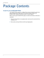
Package Contents
Package Contents
Unpacking the EP4650/EP5550
The EP4650/EP5550 is packed in a cardboard box and may be banded as part of two
types of custom pallets, depending on the number of displays shipped. The
EP4650/EP5550 is packed using foam to protect it during shipping.
Before unpacking the EP4650/EP5550, prepare a stable, level and clean surface near a
wall outlet.
1 Place the LCD panel box in an upright position and remove the carton locks from
the bottom first.
2 Remove the entire top of the box and the top shipping foam.
8
EP4650/EP5550 User Manual
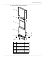
Unpacking the EP4650/EP5550
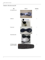
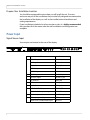
3 Remove the accessory bag and packing list.
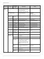
Item
Description
Quantity
1
LCD panel
1
2
Carton
1
3
Foam Cushion Top
1
4
Foam Cushion Bottom
1
5
Polyurethane Bag
1
6
Accessory Bag
1
7
Carton Lock
4
EP4650/EP5550 User Manual
9
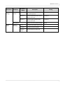
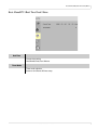
Contents of the Accessory Kit
Contents of the Accessory Kit
Part
10
Picture
Quantity
VGA Cable (D-sub)
1
USB Drive
1
Power cord
1
IR extender cable
1
OSD Remote (AAA
batteries included)
1
EP4650/EP5550 User Manual
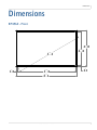
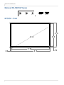
Dimensions
Dimensions
EP4560 - Front
LQ
PP
LQ
PP
LQ
PP
LQ
PP
LQ
PP
LQ
PP
LQ
PP
EP4650/EP5550 User Manual
11
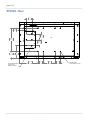
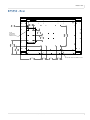
EP4560 - Rear
EP4560 - Rear
LQ
PP
LQ
PP
LQ
PP
LQ
PP
LQ
PP
LQ
LQ
PP PP
;002817,1*
+2/(6)25
0(',$3/$<(5
12
LQ
PP
LQ
PP
LQ
PP
EP4650/EP5550 User Manual
LQ
PP
;09(6$
02817,1*+2/(6
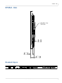
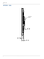
EP4560 - Side
EP4560 - Side
+'6',9:
237,21
LQ
PP
LQ
PP
LQ
PP
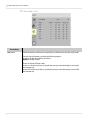
Standard Inputs
RS232C
LAN
DisplayPort
HDMI 1
HDMI 2
DVI-D
VGA
IR
PC
Audio
Audio Extender Out
In
EP4650/EP5550 User Manual
Component
Audio In
S-Video
Video
Audio In
13
Optional HD-SDI/VW Inputs
Optional HD-SDI/VW Inputs
SDI IN
SDI IN
SDI OUT
DVI OUT
VGA OUT
EP5550 - Front
LQ
PP
LQ
PP
LQ
PP
LQ
PP
14
LQ
PP
EP4650/EP5550 User Manual
LQ
PP
LQ
PP
EP5550 - Rear
EP5550 - Rear
LQ
PP
LQ
PP
LQ
PP
;0
02817,1*
+2/(6)25
0(',$3/$<(5
LQ
PP
LQ
PP
LQ
PP
LQ
PP
LQ
PP
LQ
PP
LQ
PP
EP4650/EP5550 User Manual
LQ
PP
;09(6$02817,1*+2/(6
15
EP5550 - Side
EP5550 - Side
HD-SDI/VW
237,21$/
OPTION
+'6',9:
.,7
LQ
PP
LQ
PP
LQ
PP
16
EP4650/EP5550 User Manual
Installing an EP4650/EP5550
Installing an
EP4650/EP5550
This section explains how to install an EP4650/EP5550. We suggest that you read the
entire section before you attempt to install the unit.
Before You Begin
Make sure you have all the items in these lists before you begin unpacking and
installing your EP4650/EP5550(s).
Tools/Equipment List
Depending on your installation, you may need one or more of the following items:
•
•
•
•
•
String/string level
Digital/laser level
Ladders/lift
Back brace
Stud finder (if hanging display on a wall)
Other Things You May Need
• LCD screen cleaner or LCD wipes - available at most electronics stores
• At least two very strong people to help lift units into place
Plan Your Installation
You should have a detailed plan of how the units are to be configured. The plan
should include calculations for the following:
•
•
•
•
Power (maximum of five units per 20A circuit for 115V operation)
Cable runs
Ventilation and cooling requirements
If hanging display on a wall, location of studs in the wall
EP4650/EP5550 User Manual
17
Prepare Your Installation Location
Prepare Your Installation Location
You should have prepared the area where you will install the unit. If custom
enclosures are part of the installation, they must be fully designed to accommodate
the installation of the displays, as well as the installed unit and ventilation and
cooling requirements.
If your installation included a lot of construction or dust, it is highly recommended
that you clean all of the screens after the wall installation and configuration are
complete.
Power Input
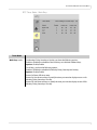
Signal Source Input
Source inputs are located on the rear of the display.
RS232C
LAN
DisplayPort
HDMI 1
HDMI 2
DVI-D
VGA
IR
PC
Audio
Audio Extender Out
In
Name
18
Component
Connector
RS232C input
D-Sub 9-pin
LAN input
RJ45
DisplayPort
DisplayPort
HDMI 1 input
HDMI
HDMI 2 input
HDMI
DVI-D input
D-Sub 24-pin
VGA (PC) input
D-Sub 15-pin
PC audio in
Mini jack
IR Extender
Mini jack
Audio Out
Mini jack
Y-Pb-Pr (Y-Cb-Cr) input
RCA G/B/R
Audio In for Component input
RCA L/R
S-video input
Mini Din 4-pin
Video (composite) input
RCA
Audio In for S-Video/Video input
RCA L/R
EP4650/EP5550 User Manual
Audio In
S-Video
Video
Audio In
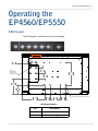
Operating the EP4560/EP5550
Operating the
EP4560/EP5550
OSD Keypad
The OSD keypad is located on the rear of the display.
LQ
PP
LQ
PP
LQ
PP
;0
02817,1*
+2/(6)25
0(',$3/$<(5
LQ
PP
LQ
PP
LQ
PP
LQ
PP
LQ
PP
LQ
PP
LQ
PP
LQ
PP
;09(6$02817,1*+2/(6
OSD Keypad Buttons
Key
Descriptions
Power
Power on/Power off
Source
Source selection (toggle)
EP4650/EP5550 User Manual
19
Remote Control Receiver
OSD Keypad Buttons
Menu Right/Increase value
Menu Left/Decrease value
▲
Menu Up
▼
Menu Down
Menu/Exit
Menu/Exit
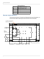
Remote Control Receiver
The remote control receiver is located near the keypad on the rear of the display. Use
the IR extender cable for operating the remote from the front of the display.
Power ON standby indicator,
Remote control receiver
LQ
PP
LQ
PP
LQ
PP
;0
02817,1*
+2/(6)25
0(',$3/$<(5
LQ
PP
LQ
PP
LQ
PP
LQ
PP
LQ
PP
20
LQ
PP
LQ
PP
EP4650/EP5550 User Manual
LQ
PP
;09(6$02817,1*+2/(6
LED Indicators
LED Indicators
The LED indicator light is located on the rear of the display near the keypad. The
following table explains what the different colors and blink patterns mean.
LED On
Power Status
Condition
Green
Power on
Blinking Orange
No signal
Orange
Power saving mode
Off
AC off
Off
Power off
Using the Display in Portrait Mode
When using the display in the portrait position and looking at the rear of the display,
it should be rotated according to the arrow stickers on the back of the display. This
will allow for proper ventilation. Then select the OSD rotation of landscape or portrait
on the OSD menu (MAIN MENU > BASIC > OSD ROTATION).
Caution: Improper ventilation may shorten the life of the display.
EP4650/EP5550 User Manual
21
Using the Remote Control
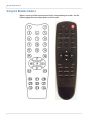
Using the Remote Control
Below is a picture of the remote control and its corresponding Hex codes. See the
following page for button descriptions and Hex codes.
22
EP4650/EP5550 User Manual
Using the Remote Control
Num
1
Function
INFO
2
Customer
Code
Hex Code
40AF
04FB
Provides source and resolution
information
40AF
1CE3
Turns the EP4650/EP5550 on and off
Description
3
VGA
40AF
07F8
Selects the PC’s VGA source
4
DVI
40AF
08F7
Selects the PC’s DVI source
5
HDMI 1
40AF
09F6
Selects the HDMI source 1
6
COMP
40AF
0AF5
Selects the Component source
7
AV
40AF
0BF4
Selects the Composite video source
8
HDMI 2
40AF
0CF3
Selects the HDMI source 2
9
P-position
40AF
1AE5
Selects the PIP position
10
DisplayPort
40AF
15EA
Selects the DisplayPort source
11
SDI 1
40AF
10EF
Selects the HD-SDI source 1
12
PIP
40AF
11EE
Turns the PIP feature on and off
13
S-V
40AF
0DF2
Selects the S-Video source
14
SDI 2
40AF
16E9
Selects the HD-SDI source 2
SWAP
40AF
06F9
Swaps the main source & sub source
picture
16
P-SOURCE
40AF
13EC
Selects the secondary subsource
17
▲
40AF
02FD
Navigates up through submenus and
settings
40AF
01FE
Navigates back through submenus and
settings
40AF
0EF1
Opens the EP4650/EP5550’s on-screen
menu system. When the menu system
is already open, pressing this button
will select the previous submenu.
40AF
03FC
Navigates forward through submenus
and settings
15
18
19
20
MENU
EP4650/EP5550 User Manual
23
Locking/Unlocking the OSD Menus
Num
Function
Customer
Code
Hex Code
Description
21
▼
40AF
19E6
Navigates down through submenus
and settings
22
ENTER
40AF
12ED
Selects highlighted menu choices
23
EXIT
40AF
05FA
Closes the menu system
SCALING
40AF
14EB
Toggles between different aspect ratios
(Auto, Native, 4 x 3, 16 x 9, 16 x 10 and
Letterbox)
27
FREEZE
40AF
43BC
Freezes the current source image
28
MUTE
40AF
00FF
Turns off the sound
29
BRIGHT
40AF
17E8
Adjusts the brightness
30
CONTRAST
40AF
18E7
Adjusts the contrast
AUTO
40AF
1EE1
Synchronizes the EP4650/EP5550 to
the source
SOURCE
40AF
0FF0
Allows selection of the different
sources
33
VOLUME -
40AF
1BE4
Decreases the sound volume
34
VOLUME +
40AF
1DE2
Increases the sound volume
26
31
32
Locking/Unlocking the OSD Menus
You can lock or unlock the OSD menus by pressing a series of key commands on the
remote control. To lock the menu, press the following keys on the remote in the
order listed: ENTER, ENTER, EXIT, EXIT, ENTER and EXIT. To unlock it, simply follow the
same sequence.
Depending on whether you locked or unlocked the menu, you will see one of the
following messages on the screen.
24
EP4650/EP5550 User Manual
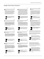
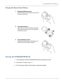
Changing the Remote Control Battery
Changing the Remote Control Battery
1
Remove the battery cover.
Slide back and remove the battery cover in the
direction of the arrow.
2
Insert the batteries.
Align and insert two AAA batteries according
to their plus and minus ports (as indicated in
the remote control).
3
Close the battery cover.
Replace the battery cover in the direction of
the arrow and snap it back into place.
Turning the EP4650/EP5550 On
1 Insert the power cord into EP4650/EP5550 and into the power outlet.
2 Ensure the AC switch is set to “—“.
3 Press the power button on the remote or side control panel.
EP4650/EP5550 User Manual
25
Turning the EP4650/EP5550 Off
Turning the EP4650/EP5550 Off
With the power on, press the power button on the remote or side control panel to
put the LCD panel in a standby mode. To turn off power completely, turn the AC
switch to “O” or disconnect the AC power cord from the power outlet.
Note: If there is no signal for a certain period of time, the LCD panel will automatically go into
standby mode.
Adjusting the Volume
1 Using the remote, press the VOLUME - or VOLUME + to increase or decrease the
volume.
2 Press the MUTE button to temporarily turn off all sound. To restore the sound,
press the MUTE button again.
26
EP4650/EP5550 User Manual
Selecting the Input Source
Selecting the Input Source
1 Do one of the following:
• Using the remote, press the desired source button (VGA, HDMI 1, HDMI 2,
DISPLAYPORT, VIDEO (COMPOSITE), S-V (S-VIDEO), COMPONENT, SDI 1 OR SDI 2.).
• Press the source button on the EP4650/EP5550’s keypad. Use the arrow buttons
(▲ ▼) to select one of the following input sources and press ENTER: VGA, HDMI
1, HDMI 2, DVI, DISPLAYPORT, COMPOSITE VIDEO, S-VIDEO, COMPONENT, SDI 1
OR SDI 2.
Standard Inputs
Standard Inputs Plus Optional SD-HDI
VGA
HDMI 1
HDMI 2
DVI
DisplayPort
Composite Video
S-Video
Component Video
SDI 1
SDI 2
Note: When the EP4650/EP5550 cannot find a source, a “No signal” message will appear.
EP4650/EP5550 User Manual
27
PIP Mode
PIP Mode
The Picture-in-Picture mode displays a separate image within a smaller window in
addition to the main source picture that is displayed on most of the display.
1 Select the main source: Using the remote, press the desired source button (VGA,
HDMI 1, HDMI 2, COMP, VIDEO [composite] or S-V [s-video]).
2 Turn on PIP: Using the remote, press PIP.
PIP
MAIN
Large PIP
Medium PIP
Small PIP
3 To select the PIP/ subsource: Using the remote, press P-SOURCE and use the
arrow buttons (▲ ▼) to navigate to the desired subsource. Press ENTER.
4 To change the size and position of the subsource: Using the remote, press
P-POSITION to toggle through the options.
TOP RIGHT
TOP LEFT
MAIN
BOTTOM
LEFT
28
BOTTOM
RIGHT
EP4650/EP5550 User Manual
Small PIP
PIP Mode
5 To switch the main source and the subsource: Using the remote, press SWAP.
SWAP
MAIN
6 To switch audio between the main source and the subsource: Using the
remote, press AUDIO.
7 For additional PIP functionality, press MENU and navigate to the DISPLAY
SETTINGS menu. Use the arrow buttons (▲ ▼) to navigate to the desired PIP
feature and press ENTER. Press to toggle through the associated options and
press ENTER to select the highlighted option.
MAIN SOURCE
SUBSOURCE
EP4650/EP5550 User Manual
29
PIP Screen Table
8 Side by Side: Press the P-POSITION button and then “Side by side” mode. The
main source and the subsource will be on the screen display.
MAIN
PIP
PIP Screen Table
The following table shows sources that can be displayed in a PIP window when
sources in the main window are displayed.
PIP
VGA
VGA
Yes
HDMI 2
Yes
DVI
Yes
Display
Port
Video
(Composite)
S-Video
Component
HD-SDI 1
HD-SDI 2
Yes
Yes
Yes
Yes
Yes
Yes
HDMI 1
Yes
Yes
Yes
Yes
Yes
Yes
Yes
HDMI 2
Yes
Yes
Yes
Yes
Yes
Yes
Yes
Yes
Yes
Yes
Yes
Yes
Yes
Yes
Yes
Yes
Yes
Yes
Yes
M
a DVI
i DisplayPort
n Video
30
HDMI 1
Yes
Yes
Yes
Yes
Yes
Yes
Yes
Yes
Yes
Yes
Yes
Yes
S-Video
Yes
Yes
Yes
Yes
Yes
Yes
Yes
Yes
Component
Yes
Yes
Yes
Yes
Yes
Yes
Yes
Yes
Yes
HD-SDI 1
Yes
Yes
Yes
Yes
Yes
Yes
Yes
Yes
HD-SDI 2
Yes
Yes
Yes
Yes
Yes
Yes
Yes
Yes
EP4650/EP5550 User Manual
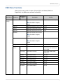
OSD Menu Functions
OSD Menu Functions
There are two menu modes: Graphics (DVI and VGA) and Video (HDMI and
DisplayPort). Any differences are notes in the table.
Main Menu
Image
Settings
Submenu
Secondary
Menu
Scheme
Description
In Video mode, select the scheme
Setting
User, Vivid, Cinema, Game, Sport
Note: Disabled in Graphics
mode
Brightness
Adjust the brightness of the screen
0~100
Contrast
Adjust the contrast of the screen
0~100
Sharpness
Adjust the sharpness of the screen
0~24
Saturation
Adjust the saturation of the screen
Note: Disabled in Graphics
mode
Hue
Adjust the hue of the screen
Note: Disabled in Graphics
mode
Backlight
Color Temp &
Gamma
Adjust the backlight
0~100
Gamma
Select the Gamma
1.85, 1.9, 1.95, 2.0, 2.05, 2.1, 2.15,
2.2, 2.25, 2.3, 2.35, 2.4, 2.45, 2.5,
2.55, 2.6, Off
Color Temp
Select the Color Temp
3200, 5000K, 6500K, 7500K,
9300K, User
Red Gain
Select the Red Gain
128~383
Green Gain
Select the Green Gain
128~383
Blue Gain
Select the Blue Gain
128~383
Red Offset
Select the Red Offset
-50~50
Green Offset
Select the Green Offset
-50~50
Blue Offset
Select the Blue Offset
-50~50
EP4650/EP5550 User Manual
31
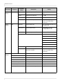
OSD Menu Functions
Main Menu
Display
Settings
Display
Settings
Secondary
Menu
Submenu
Main
PIP
Description
Setting
Aspect Ratio
Adjust the aspect ratio of the screen
Full screen, Pillar Box, Letter Box,
Native
Zoom
Adjust the zoom function
Auto Scan
Select the Auto scan function
Off, On
Select Source
Select the main input source
VGA, HDMI 1/2, DisplayPort, DVI,
Comp, S-V (s-video), Video
(composite)
PIP Mode
Select the PIP mode
Off, Large PIP, Medium PIP, Small
PIP, Side by Side
PIP Position
Select the PIP location
Bottom-Right, Top-Left
Top-Right, Bottom-Left
Aspect Ratio
Adjust the aspect ratio of the screen
Full screen, Pillar Box, Letter Box
Side by Side Scale
PIP
Main
▲ Zoom IN
▼ Zoom Out
Enter: Default
Menu: Return
Audio
Settings
32
Auto Scan
Select the Auto scan function
Off, On
Select Source
Select the main input source when
PIP mode is enabled
VGA, HDMI 1/2, DisplayPort, DVI,
Comp, S-V (s-video), Video
(composite)
Volume
Adjust the volume
0~100
Bass
Adjust the Bass volume
0~20
Treble
Adjust the Treble volume
0~20
Balance
Adjust the balance of the screen
0~20
HDMI Audio Input
Audio input control
HDMI/PC
DP Audio Input
Audio input control
DisplayPort/PC
Internal Speakers
Disable internal audio speakers
On, Off
EP4650/EP5550 User Manual
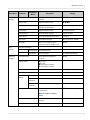
OSD Menu Functions
Main Menu
Basic
Settings
Basic
Settings
Advanced
Settings
Secondary
Menu
Submenu
Description
Setting
OSD Transparent
Adjust the OSD transparent
function
0~100
OSD Location
Adjust the OSD location
,,▲,▼
OSD Zoom
Adjust the OSD size
(Disable in portrait type)
Off, On
OSD Rotation
Adjust the OSD rotation
Landscape/Portrait
OSD Language
Select the OSD language
English/ Chinese
OSD Timeout
Select the OSD timeout seconds
5~120 sec.
Sleep Timer
Select the sleep timer
Off, 15, 30, 60, 90, 120 Min.
Power LED
LED on rear of display shows
powered on/off or standby mode
Off, On
Real Time Clock (RTC)
Current Mode
Set up Date & Time
Timer Mode
Set up schedule
User, Work Days, All Days
Auto Adjustment
Select the Auto adjustment
function
Off, On
Image Position
0~ ‐100
0 ~ 100
▲ according to resolution
▼ according to resolution
Phase
0~63
According to resolution
Clock
0~100
According to resolution
ADC Mode
Select ADC mode
Default, User
User ADC
Calibration
Perform an ADC calibration
Yes, No
Restore ADC
to Default
Reset the default ADC settings
Yes, No
Use to amplify all colors except of
people’s faces
Off, Low, Medium, High
VGA ADC
Settings
Flesh Tone
Note: Disabled in Graphics
mode
IRFM
Select the anti burn-in mode
function
Off, On
Baud rate
Setting the baud rate of the display
115200, 38400, 19200, 9600
EP4650/EP5550 User Manual
33
OSD Menu Functions
Main Menu
Advanced
Settings
Submenu
Description
Setting
Smart light control
Select the Backlight control
function DCR (Dynamic contrast) –
from the input source
Light Sensor – from ambient light
Off, DCR, Light Sensor
Wake Up From Sleep
Energy-saving function
Never Sleep
VGA Only
VGA, Digital, RS232
Ethernet
Setup
Enable
Network
Enable the network feature
Yes, No
Dynamic IP
Enable the Dynamic IP mode
Disable, Enable
Static IP
Address
Set the static IP address
255.255.255.255 (0.0.0.0)
Subnet Mask
Set the subnet mask
255.255.255.255 (0.0.0.0)
Gateway
Set the gateway address
255.255.255.255 (0.0.0.0)
DNS Address
Set the DNS address
255.255.255.255 (0.0.0.0)
Save Network
Settings
Update the IP settings to the net
device
Yes, No
Load Default
Settings
Load the default network settings
Yes, No
Device MAC
Show the unique address assigned
to network interfaces
Monitor ID
Manually select the Monitor ID of
each display
1~25
Video Wall
Disable/Enable Video Wall
Yes, No
DVI
Indemnity
Used for large video walls that have
a single digital source and DVI passthru cables. Turning on DVI
Indemnity may enhance the video
quality and reliability of pass-thru
signals.
Off, On
Power On
Delay
Select the Power On delay in
seconds for each display in the
video wall
0~1.50 (in .05 second
increments)
Frame
Disable/Enable Frame
compensation
Yes, No
Matrix X
Sets the number of displays used in
the horizontal position
1~5
Multi-Display
Control
34
Secondary
Menu
EP4650/EP5550 User Manual
OSD Menu Functions
Main Menu
Advanced
Settings
Submenu
Multi-Display
Control
Secondary
Menu
Channel
Information
Setting
Matrix Y
Sets the number of displays used in
the vertical position
1~5
Division X
Sets the horizontal position of the
display wall matrix
1~ Matrix X
Division Y
Sets the vertical position of the
display wall matrix
1~ Matrix Y
Reset to the factory default setting
Yes, No
Factory Reset
System
Status
Description
Source
Show the name of the input source
Resolution
Show the current resolution
Firmware
Version
Show the firmware of the LCD
EP4650/EP5550 User Manual
35
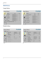
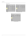
OSD Menus
OSD Menus
Image Settings
Display Settings
Main
36
PIP
EP4650/EP5550 User Manual
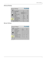
Audio Settings
Audio Settings
Basic Settings
EP4650/EP5550 User Manual
37
Basic Settings
RTC Submenus
User Mode
Same Settings On Work Days Mode
Same Settings On All Mode
38
EP4650/EP5550 User Manual
Advanced Settings
Advanced Settings
Network Settings
EP4650/EP5550 User Manual
39
Multi-Display Control
Multi-Display Control
System Status
Navigating Through the Menus
1 With the power on, press MENU. The IMAGE SETTINGS menu appears.
2 Within the menu, use ▲, ▼, , and ENTER to navigate through the menus and
adjust options.
3 Press MENU to return to the previous menu. To exit the menu system, press EXIT.
40
EP4650/EP5550 User Manual
Image Settings Menu
Image Settings Menu
This menu is used for making common image adjustments.
Scheme
Press or to select one of the following:
Options: User, Vivid, Cinema, Game, Sport
Brightness
Increases or decreases the brightness of the picture. Press or , select the
desired level, and press ENTER.
Range: 0~100
Contrast
Increases or decreases the contrast of the picture. Press or , select the
desired level, and press ENTER.
Range: 0~100
Sharpness
Adjusts the definition of the picture. Press or , select the desired level, and
press ENTER.
Range: 0~24
Saturation
Adjusts the brilliance and brightness (Video Mode only). Press or , select the
desired level, and press ENTER.
Range: 0~100
Hue
Increases or decreases the green hue (Video Mode only). Press or , select
the desired level, and press ENTER.
Range: 0~100
EP4650/EP5550 User Manual
41
Image Settings Menu
Backlight
Range: 0~100
Color Temp and Gamma
Adjusts red, green, blue gain and red, green blue offset.
Gamma
Options: Off, 1.85, 1.9, 1.95, 2.0, 2.05, 2.1, 2.15, 2.2, 2.25, 2.3, 2.35, 2.4, 2.45, 2.5,
2.55, 2.6
Color Temp
Options: User, 3200K, 5000K, 6500K, 7500K and 9300K.
Red Gain
Set Color Temperature to “User Mode” to adjust this setting.
Range: 128~383
Green Gain
Set Color Temperature to “User Mode” to adjust this setting.
Range: 128~383
Blue Gain
Set Color Temperature to “User Mode” to adjust this setting.
Range: 128~383
Red Offset
Set Color Temperature to “User Mode” to adjust this setting.
Range: -50~50
Green Offset
Set Color Temperature to “User Mode” to adjust this setting.
Range: -50~50
Blue Offset
Set Color Temperature to “User Mode” to adjust this setting.
Range: -50~50
42
EP4650/EP5550 User Manual
Display Settings Menu
Display Settings Menu
Main
Display Setting Mode
Aspect Ratio
Changes the picture’s aspect ratio
Press or to select the following options:
Options: Full screen, Pillar Box, Letter Box, Native
Zoom
Range: 0~10
Auto Scan
Range: On, Off
Select Source
Options: HDMI 1, HDMI 2, SDI 1, SDI 2, VGA, Component, S-Video and Video
(composite)
PIP
PIP Mode
Options: Off, Large PIP, Middle PIP, Small PIP and Side-by-Side
PIP Position
Options: Bottom-Right, Top-Left, Top-Right and Bottom-Left
EP4650/EP5550 User Manual
43
Audio Settings Menu
Aspect Ratio
Options: Full screen, Pillar Box, Letter Box
Side by Side Scale
Submenu Options: Zoom In, Zoom Out, Main, PIP, Default and Return
Auto Scan
Options: On, Off
Select Source
Options: HDMI 1, HDMI 2, SDI 1, SDI 2, VGA, Component, S-Video and Video
(composite)
Audio Settings Menu
Volume
Adjust the sound. Press or , select the desired level, and press ENTER.
Range: 0~100
Bass
Adjust the low tones (bass). Press or , select the desired level, and press
ENTER.
Range: 0~20
Treble
Adjust the high tones (treble). Press or , select the desired level, and
press ENTER.
Range: 0~20
44
EP4650/EP5550 User Manual
Basic Settings Menu
Balance
Adjust the balance of the left and right speakers. Press or , select the
desired level, and press ENTER.
Range: 0~20
HDMI Audio Input
Select HDMI or PC audio input mode.
DP Audio Input
Select DisplayPort or PC audio input mode.
Internal Speakers
Disable or enable internal audio speakers.
Basic Settings Menu
This menu is used to make initial setup adjustments to the OSD (On-Screen Display)
menu and other on-screen messages.
OSD Transparent
Set the menu transparency. Press or to select the desired level, and press ENTER.
Range: 0~100
OSD Location
Adjust the menu location on the EP4650/EP5550 (Up, Down, Left, Right).
OSD Zoom
Options: On, Off
EP4650/EP5550 User Manual
45
Basic Settings Menu
OSD Rotation
Select the OSD Rotation. Press or to select the rotation.
Options: Landscape or Portrait
OSD Language
Options: English and Chinese
OSD Timeout
Options: 5~120
Sleep Timer
Set a period of time after which the EP4650/EP5550 will automatically switch to
standby mode. Press or to select the desired time limit.
Options: Off, increments of 15, 30, 45, 60, 90 or 120 minutes
Power LED
LED on rear of display shows powered on/off or standby mode.
Options: On, Off
Real Time Clock
Set the date, and switch the alarm on and off. Use ▲, ▼, , to adjust these options.
46
EP4650/EP5550 User Manual
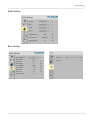
Basic Menu/RTC (Real Time Clock) Menu
Basic Menu/RTC (Real Time Clock) Menu
Real Time
Current time setting
Year/Month/Date, Hour: Minutes
Timer Mode
Timer mode selection
Power on and Power off timer setup
EP4650/EP5550 User Manual
47
Basic Menu/RTC (Real Time Clock) Menu
RTC Timer Mode - User
Timer Mode
User mode
Select the power on/off timer and specify the on/off times for each day of the week.
For each day of the week, you have the following options:
Enable or Disable the schedule of the day
Options: Disable, Enable
Power On/Power Off timer setup.
Power On: Use the arrow keys to specify the time you want the display to turn on for
the selected day.
Power Off: Use the arrow keys to specify the time you want the display to turn off for
the selected day.
48
EP4650/EP5550 User Manual
Basic Menu/RTC (Real Time Clock) Menu
RTC Timer Mode - Work Days
Timer Mode
Work Days mode
For Monday-Friday, Saturday or Sunday, you have the following options:
Enable or Disable the schedule of the work days or individual weekend days.
Options: Disable, Enable
For all days, you have the following options:
Enable or Disable the schedule for Monday-Friday, Saturday and Sunday.
Options: Disable, Enable
Power On/Power Off timer setup.
Power On: Use the arrow keys to specify the time you want the display to turn on for
Monday-Friday, Saturday or Sunday.
Power Off: Use the arrow keys to specify the time you want the display to turn off for
Monday-Friday, Saturday or Sunday.
EP4650/EP5550 User Manual
49
Basic Menu/RTC (Real Time Clock) Menu
RTC Timer Mode - All Days
Timer Mode
All Days mode
Select all days of the week power on/off timer.
For all days, you have the following options:
Enable or Disable the schedule for all days of the week
Options: Disable, Enable
Power On/Power Off timer setup.
Power On: Use the arrow keys to specify the time you want the display to turn on for all
days of the week.
Power Off: Use the arrow keys to specify the time you want the display to turn off for all
days of the week.
50
EP4650/EP5550 User Manual
Advanced Settings Menu
Advanced Settings Menu
Auto Adjustment
Forces the ep46L/ep55L to reacquire and lock to the input signal. This is useful
when the signal quality is marginal.
Note: This feature does not continually reacquire the signal. It only does so each
time you select this option.
Options: No, Yes
Image Position
Adjust the image location (VGA Mode only).
Options: Up, Down, Left, Right
Phase
Range: 0~63 (VGA Mode only)
Clocks
Range: 0~100 (VGA Mode only)
VGA ADC Settings
Select the ADC setting, User ADC Calibration, or restore factory default ADC
setting.
Options: Default, User
EP4650/EP5550 User Manual
51
Advanced Settings Menu
Flesh Tone
This feature is used to amplify all colors except that of people’s faces.
Options: Off, Low, Medium and High (Video Mode only)
IRFM
Creates slight frame motion to help avoid image retention.
Options: On
Baud Rate
Options: 115200, 38400, 19200, 9600
Smart Light Control
Options: Off, DCR, Light Sensor
Wake Up From Sleep
Allows you to configure the display to “wake up” when it receives a digital signal
through the DisplayPort, HDMI or DVI connectors. With VGA Only, the display can
only “wake up” by sending an analog video signal through the VGA connector.
Options:
Never Sleep - The display will never enter a power saving mode.
VGA Only - The display will enter a power saving mode if it cannot sync for five
minutes with the DisplayPort, HDMI or DVI. If the sync is present, the display
will “wake up” again.
VGA, Digital, RS232 - The display will enter a power saving mode if it cannot
sync for five minutes with any source.
Ethernet Setup
Configure Network settings. See "Setting Up Email Alerts" on page 69 for more
information.
Multi-Display Control
Used for displaying one image across multiple displays.
Factory Reset
Restores all settings to their defaults.
Options: No, Yes
52
EP4650/EP5550 User Manual
Advanced Settings Menu
Advanced Settings - Ethernet Setup Submenu
Enable Network
Enable the network feature
Options: No, Yes
Dynamic IP
Enable DHCP for dynamic IP address assignment.
Options: Disable, Enable
Note: When dynamic IP is enabled, the parameters received from the DHCP server
are shown in the STATIC IP ADDRESS, SUBNET MASK, GATEWAY and DNS ADD
lines.
Static IP Address
Set the static IP address when the DYNAMIC IP line is disabled or view it when the
DYNAMIC IP line is enabled.
Range: 255.255.255.255 (0.0.0.0)
Subnet Mask
Set the subnet mask when the DYNAMIC IP line is disabled or view it when the
DYNAMIC IP line is enabled.
Range: 255.255.255.255 (0.0.0.0)
Gateway
Set the gateway address when the DYNAMIC IP line is disabled or view it when
the DYNAMIC IP line is enabled.
Range: 255.255.255.255 (0.0.0.0)
EP4650/EP5550 User Manual
53
Advanced Settings Menu
DNS Address
Set the DNS address when the DYNAMIC IP line is disabled or view it when the
DYNAMIC IP line is enabled.
Range: 255.255.255.255 (0.0.0.0)
Save Network Settings
Save the network configuration when the DYNAMIC IP line is disabled.
Options: No, Yes
Email Alert
Enable/disable the following email alerts:
POWER STATUS ALERT - Sent when the unit is turned on or off.
SOURCE STATUS ALERT - Sent when a different source is selected.
SIGNAL LOST ALERT - Sent when the input sync is lost.
Load Default Settings
Load default network settings
Options: No, Yes
Device MAC
Shows the unique address assigned to network interfaces.
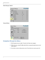
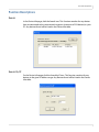
User ADC Calibration
1 When using VGA as a signal source, go to ADVANCED SETTINGS in the OSD menu,
select VGA ADC SETTINGS and then select USER ADC CALIBRATION.
2 A warning message (see image below) will appear to help you ensure that the
correct image is displayed on screen before ADC calibration begins.
a The image in the green boxes, displayed on both side of the screen, has to be
white and black in order to run the calibration accurately (the black and white
image can be made using software like Microsoft Paint).
b The white in the left green box has to be the brightest white.
54
EP4650/EP5550 User Manual
Advanced Settings Menu
c
The black in the right box has to be the darkest black.
3 After the correct image is displayed, click “Yes” to begin ADC calibration.
4 During the calibration process, the following message will appear to notify you to
wait for the calibration.
5 After the calibration is complete, you will see one of two messages.
Advanced Settings - Multi-Display Control Submenu
The menu is used for displaying one image across multiple displays. The software
allows you to tile up to a 5 x 5 array. With a DVI signal, you can loop up to nine
displays. With a VGA signal, you can loop up to four displays. Therefore, it may be
necessary to use a splitter to obtain the signal quality needed to drive a larger video
wall.
It is also important to note that the maximum cable length between displays is three
meters.
EP4650/EP5550 User Manual
55
Advanced Settings Menu
Monitor ID
Used to manually set the Monitor ID of each display in the video wall.
Options: 1-25
Video Wall
Used for displaying one image across multiple displays.
Options: Yes, No
Note: If No is selected, all of the options below the Power On Delay line will be
grayed out.
DVI Indemnity
Used for large Matrix walls that have a single digital source and DVI pass-thru
cables. Turning DVI Indemnity may enhance the video quality and reliability of
pass-thru signals.
Options: On, Off
Power On Delay
When powering on a video wall, this feature staggers the power on sequence so
that all displays will not turn on at once, reducing current requirements.
Options: 0~1.50 (in .05 second increments)
Frame
This feature enables or disables frame compensation.
Options: Yes, No
56
EP4650/EP5550 User Manual
System Status Menu
Matrix X
Sets the number of displays used in the horizontal position
Options: 1-5
Matrix Y
Sets the number of displays used in the vertical position
Options: 1-5
Division X
Sets the horizontal position of the display wall matrix
Options: 1~ Matrix X
Division Y
Sets the vertical position of the display wall matrix
Options: 1~ Matrix Y
System Status Menu
This read-only menu provides information about the active sources and the latest
firmware version.
EP4650/EP5550 User Manual
57
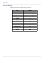
Default Settings
Default Settings
The following table shows the default settings for the LCD.
58
Item
Default
Power switch
Off
Scheme
User
Brightness
50
Sharpness
12
Backlight
80
Contrast
50
Color temperature
9300K
Source auto detection
Off
OSD language
English
Smart light control
On
IRFM
Off
Baud rate
19200
EP4650/EP5550 User Manual
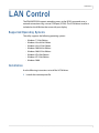
LAN Control
LAN Control
The EP4650/EP5550 supports extending access to the RS232 commands over a
network connection using a virtual COM port (VCOM). The VCOM driver installer is
included on the USB drive that came with your display.
Supported Operating Systems
The utility supports the following operating systems:
•
•
•
•
•
•
•
•
Windows 7 32-bit Edition
Windows Vista 64-bit Edition
Windows Vista 32-bit Edition
Windows 2003 64-bit Edition
Windows 2003 32-bit Edition
Windows XP 64-bit Edition
Windows XP 32-bit Edition
Windows 2000
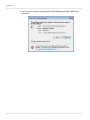
Installation
Use the following instructions to install the VCOM driver.
1 Launch the vcomsetup.exe file.
EP4650/EP5550 User Manual
59
Installation
2 You may see a security warning similar to the following example. Click Run to
continue.
60
EP4650/EP5550 User Manual
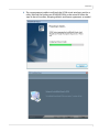
Installation
3 The vcomsetup.exe installer installs both the VCOM virtual serial port and also a
utility (WinPcap) for finding your EP4650/EP5550s on the network. Follow the
steps in the two installers, accepting defaults and license agreements as needed.
EP4650/EP5550 User Manual
61
Installation
4 When the installers are finished, you will see a VCOM icon on your desktop and
you find two new folders in your start menu: IC Plus corp (with VCOM sub folder)
and WinPcap. If you need to uninstall the software, there are shortcuts to uninstall
from these menus.
62
EP4650/EP5550 User Manual
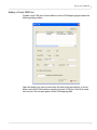
Configuring VCOM
Configuring VCOM
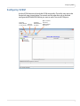
Use the VCOM shortcut to launch the VCOM setup utility. The utility starts up on the
Device Info page, shown below. The controls on this page allow you to find and
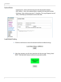
configure each EP4650/EP5550 that you want to access via virtual COM ports.
Search for
EP4650/EP5550 Search by
in same domain IP address
Open a browser
Configure
and link to
EP4650/EP5550 EP4650/EP5550
IP address
web service
EP4650/EP5550 User Manual
63
Configuring VCOM
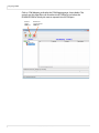
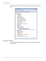
Click on COM Mapping to display the COM Mapping page, shown below. The
controls on this page allow you to make virtual COM ports and select the
EP4650/EP5550 to which you want to map each virtual COM port.
Create a
virtual
COM port
64
Remove an
existing virtual
COM port
EP4650/EP5550 User Manual
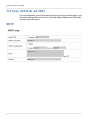
Function Descriptions
Function Descriptions
Search
In the Device Info page, click the Search icon. This function searches for any devices
that are connected to the same network segment (maximum of 254 devices) as your
PC. Any devices found will be listed in the Device Info table.
Search By IP
On the Device Info page, click the Search by IP icon. This function searches for any
devices in the given IP address range. Any devices found will be listed in the Device
Info table.
EP4650/EP5550 User Manual
65
Configure IP Address
Configure IP Address
This function allows you to configure the network settings of the selected
EP4650/EP5550 device. We recommend using the on-screen menus or the web
interface described in the User Guide instead of this function.
Note: To cancel this function, scroll to the bottom and click the Cancel button.
Web
Click the Web icon to launch your default browser and link it to the EP4650/EP5550
web service.
66
EP4650/EP5550 User Manual
Adding a Virtual COM Port
Adding a Virtual COM Port
To add a virtual COM port, click the Add icon on the COM Mapping page to open the
following dialog window.
Select the display you want to control from the table and accept defaults, as shown.
Make a note of the COM number assigned to the new VCOM port. Click OK to create
the new port. The new port appears in the COM Mapping table.
EP4650/EP5550 User Manual
67
Removing a COM Port
You can view details for the virtual COM port device using Device Manager, shown
below.
Removing a COM Port
On the COM Mapping page, select the COM port you want to delete and click the
REMOVE button.
68
EP4650/EP5550 User Manual
Setting Up Email Alerts
Setting Up Email Alerts
The web service allows you to configure the settings required to send email alerts. If
you are not using email alerts, you do not need to use the web service and can skip
this section.
Login
When you direct your browser to the network IP address of the EP4650/EP5550, you
are prompted to login as shown here.
The default ID is admin and the default password is system.
Note: Cookies and JavaScript must be enabled in your browser.
Note: If your session times out or if you enter an incorrect ID or password, you will see the
following message.
EP4650/EP5550 User Manual
69
Login
When you first login, you will see the System Status page, as shown here.
70
EP4650/EP5550 User Manual
Administrator
Administrator
Click on the word Administrator under the Planar logo to show/hide these menu
items.
Authentication Configuration
Set user ID and password for login to the web service.
System IP Configuration
You can view and/or change the network settings here. However, for best results, we
recommend that you use the on-screen display menus, as described in "Advanced
Settings - Ethernet Setup Submenu" on page 53.
If your network requires a VLAN tag, your network administrator will give you a
number from 1 to 4094 to enter here.
EP4650/EP5550 User Manual
71
System Status
System Status
• Kernel version - Shows the firmware version for the network interface.
• MAC Address - Shows the unique address assigned to the network interface.
• Nickname - Enter a device tag, up to 12 characters. This tag will appear in email
alerts, which help you identify the source of the alert.
Load Default Setting
1 Click the LOAD button to return the network interface to default settings.
2 After a few seconds, you will see a green box with the message “Setting Saved
RESET.” Click the RESET button to restart the network interface.
72
EP4650/EP5550 User Manual
Firmware Update and Boot Loader Upgrade
3 Make sure the IP address in your browser is correct and then click OK.
4 When the process is complete, you should see the login page again.
Firmware Update and Boot Loader Upgrade
In most cases, you will not need to update firmware for the network interface. If you
do, contact Planar’s Technical Support Department. See "Accessing Planar’s Technical
Support Website" on page 81 for more information.
WARNING! Do not use the controls in these two sections unless you have received a specific
procedure and firmware from Planar. Following improper procedures can disable the network interface and require factory repair service.
EP4650/EP5550 User Manual
73
TCP Mode, UDP Mode and UART
TCP Mode, UDP Mode and UART
For normal operation, you will not need to change any settings on these pages. If you
do need to change information, Planar’s Technical Support Department will provide
you with more information.
SMTP
74
EP4650/EP5550 User Manual
Reset Device
Your network administrator must provide information for the following fields:
• Enable SMTP - Make sure this checkbox is checked. Port 25 is the default.
• SMTP Server Address - Name or IP address of the mail server.
• SMTP Login Information - If required, check the ENABLE box and enter a
username and password.
• Mail to - Enter the destination email addresses. Separate multiple addresses
with a semi-colon.
• Mail from - Enter the email address from which you want to send alerts.
You can edit the subject and body of the email warnings, which are sent when there
is a power status change, source change and signal lost. The SMTP 04 and 05
warnings are not used.
Reset Device
Click the RESET button to reboot the network interface. Note that the current
settings are not changed.
EP4650/EP5550 User Manual
75
Signal Compatibility
25.175
O
O
-
-
-
O
O
-
37.861
72.809
31.5
O
O
-
-
-
O
O
-
37.5
75
31.5
O
O
-
-
-
O
O
-
43.269
85.008
36
O
O
-
-
-
O
O
-
35.156
56.25
36
O
O
-
-
-
O
O
-
37.879
60.317
40
O
O
-
-
-
O
O
-
48.077
72.188
50
O
O
-
-
-
O
O
-
46.875
75
49.5
O
O
-
-
-
O
O
-
53.674
85.06
56.25
O
O
-
-
-
O
O
-
48.363
60.004
65
O
O
-
-
-
O
O
-
56.476
70.069
75
O
O
-
-
-
O
O
-
60.023
75.029
78.75
O
O
-
-
-
O
O
-
68.677
84.997
94.5
O
O
-
-
-
O
O
-
WXGA1366 x 768
47.72
59.799
84.75
O
O
-
-
-
O
O
-
1280 x 720
44.444
59.98
64
O
O
-
-
-
O
O
-
44.772
59.86
74.5
O
O
-
-
-
O
O
-
56.456
74.78
95.75
O
O
-
-
-
O
O
-
47.776
59.87
79.5
O
O
-
-
-
O
O
-
47.396
59.995
68.25
O
O
-
-
-
O
O
-
68.633
84.837
117.5
O
O
-
-
-
O
O
-
49.306
59.91
71
O
O
-
-
-
O
O
-
49.702
59.81
83
O
O
-
-
-
O
O
-
1152 x 864
67.5
75
108
O
-
-
-
-
-
O
-
1280 x 1024
63.981
60.02
108
O
O
-
-
-
O
O
-
79.976
75.025
135
O
O
-
-
-
O
O
-
SVGA 800 x 600
XGA 1024 x 768
1280 x 768
1280 x 800
SXGA
76
HD-SDI*
59.94
EP4650/EP5550 User Manual
DVI
S-Video
VGA
Display
Port
Dot clock
(MHz)
31.469
Video
fV (Hz)
VGA 640 x 480
HDMI
Timing
fH (KHz)
VESA
Component
Signal Compatibility
HD-SDI*
Display
Port
Video
O
-
-
-
O
O
-
64.744
59.95
101
O
-
-
-
-
-
O
-
65.317
59.98
121.75
O
-
-
-
-
-
O
-
55.469
59.901
88.75
O
O
-
-
-
O
O
-
55.935
59.88
106.5
O
O
-
-
-
O
O
-
64.674
59.883
119
O
O
-
-
-
O
O
-
65.29
59.954
146.25
O
O
-
-
-
O
O
-
UXGA 1600 x 1200
75
60
162
O
O
-
-
-
O
O
-
1920 x 1080
66.587
59.93
138.5
O
O
-
-
-
O
O
-
WUXA 1920 x 1200
74.038
59.95
154
O
O
-
-
-
O
O
-
NTSC
15.734
29.97
13.5
-
-
480i
O
O
-
-
487i
PAL
15.625
25
13.5
-
-
576i
O
O
-
-
576i
480p
31.5
60
27.03
O
-
O
-
-
O
O
-
576p
31.25
50
27
O
-
O
-
-
O
O
-
720p
37.5
50
74.25
O
-
O
-
-
O
O
O
1280 x 720
44.995
59.94
74.176
O
-
O
-
-
O
O
O
45
60
74.25
O
-
O
-
-
O
O
O
1080i
28.13
50
74.25
O
-
O
-
-
O
O
O
1920 x 1080
33.716
59.94
74.176
O
-
O
-
-
O
O
O
33.75
60
74.25
O
-
O
-
-
O
O
O
27
24
74.25
O
-
-
-
-
-
O
O
28.125
25
74.25
-
-
-
-
-
-
-
O
33.716
29
74.18
-
-
-
-
-
-
-
O
33.75
30
74.25
-
-
-
-
-
-
-
O
56.25
50
148.5
O
-
O
-
-
O
O
-
67.433
59.94
148.352
O
-
O
-
-
O
O
-
67.5
60
148.5
O
-
O
-
-
O
O
-
1400 x 1050
WSXGA+ 1680 x 1050
1080p 1920 x 1080
VGA
DVI
O
1440 x 900
HDTV
S-Video
157.5
SXGA+
EDTV
Component
fV (Hz)
85.024
HDMI
fH (KHz)
91.146
Timing
SDTV
Dot clock
(MHz)
Signal Compatibility
Note: 480i means supported 480i @ 60 Hz (YPbPr). 576i means supported 576i @ 50 Hz
(YPbPr)
* HD-SDI is an optional feature.
EP4650/EP5550 User Manual
77
Specifications
Specifications
Item
LCD panel
Specification
Resolution
1920 x 1080
Brightness (typ.)
EP4650
EP5550
Performance
700 cd/m2
700 cd/m2
Contrast Ratio
Minimum 3000:1, Typical 4000:1
Response Time
EP4650
EP5550
5.5 ms
5.5 ms
Aspect Ratio
16:9
Horizontal Sync.
Positive/Negative
Vertical Sync.
Positive/Negative
Connectors
Display port/HDMI x 2 / SDI x 2 / VGA / DVI / PC Audio in
/ IR Extender / Line Out / Component (w/ audio) / SVideo / Video-composite (w/ audio)
Auto Adjust
Clock, Phase, H-Position and V-Position
Screen Scaling
VGA/SVGA/XGA/WXGA/HD
Full Screen Display
Frame Delay
Graphics mode
Interlaced video mode
Progressive video mode
1 frame
3 frames
2 frames
Note: For HD-SDI/VW, add 200-300 microseconds
Framelock
50-60 Hz
Power Management
VESA DPMS, DVI DMPM
OSD Language
English and Chinese
Power Source
Input Voltage/Frequency
AC 100V~240V, 50-60 Hz
Power
Consumption
Operation Mode (Max)
EP4650
EP5550
135W (BTU calculation: 135W x 3.42 = 461.7 BTU/hr)
155W (BTU calculation: 155W x 3.42 = 530.1 BTU/hr)
Power Saving Mode (Max)
.5W
78
EP4650/EP5550 User Manual
Specifications
Item
Physical
Specification
Standard Dimensions (W x H x D)
EP4650
41.6” (W) x 24.1” (H) x 2.0” (D)
1057.1mm (W) x 611.9mm (H) x 51.0mm (D)
EP5550
49.2” (W) x 28.3” (H) x 2.1” (D)
1248.6mm (W) x 719.4mm (H) x 52.2mm (D)
Note: For HD-SDI/VW models, add 0.9” (22mm) depth
Net Weight
EP4650
50.3lbs (22.8kg)
EP5550
66.6lbs (30.2kg)
Gross Weight w/ packing
Environment
Function
EP4650
61.3lbs (27.8kg)
EP5550
82.0lbs (37.2kg)
Storage Temperature
Min -4°F ~ Max 140° F (-20°C ~ Max 60°C)
Operating Temperature
Min 41°F ~ 104°F (5°C ~ Max 40°C)
Humidity
80% RH @ 104°F (40°C)
Plug and Play
DDC 2B Compliance
RS232
D-Sub 9-pin / RJ45 in & out
OSD key
7 keys (
Wall mount
EP4650/EP5550 User Manual
, SOURCE,
▲, ▼, , , MENU/EXIT)
400 x 400, 400x 200 VESA standards
79
Troubleshooting
Troubleshooting
Before calling service personnel, please check the following table for a possible cause
of the problem you are experiencing. Please note the following:
• Perform the adjustments according to "Operating the EP4560/EP5550" on
page 19.
• If the problem you have experienced isn’t described below or you can’t correct
the problem, stop using the EP4650/EP5550 and contact Planar’s Technical
Support Department. (See "Accessing Planar’s Technical Support Website" on
page 81)
Issue
Check for the following
No image is displayed
Make sure the correct source is selected.
Make sure the main power switch is turned ON.
Check that the source equipment is operating correctly.
Make sure the input signal is compatible with this display.
The image is not centered
Make sure the input signal is compatible with this display.
The remote control doesn’t
work
Make sure the batteries are new and are installed correctly.
Ensure the remote is aimed at the IR sensor.
Make sure the remote control sensor is plugged in
correctly.
Make sure the remote is aimed towards the back of the
display, where the sensor is located.
The picture color looks poor
Check the picture settings.
Reset the display.
If you are using YUV terminals, make sure cables are
correctly connected.
Check ADC calibration. (See "User ADC Calibration" on
page 54)
80
EP4650/EP5550 User Manual
Accessing Planar’s Technical Support Website
Accessing Planar’s
Technical Support
Website
1 Go to http://planarpartners.com
2 Once you enter your login and password, you can access downloadable utility
software, new firmware and user manuals.
Downloading Additional Documentation and Firmware
Some of the other documents for the EP4650/EP5550, which are or will be available
on www.planar.com, are listed below:
Document Name
Contents
User Guide
Information for installers and end users to install
and use displays.
RS232 Codes User Manual
Technical information about the product, such
as display mode information and how to use
RS232 commands to control displays.
EP4650/EP5550 User Manual
81
Downloading Utility Software
Downloading Utility Software
82
1
Go to http://planarpartners.com.
2
Enter your login and password information.
3
Under the Service heading on the left pane, select the Software/Firmware subheading.
Then select the LCD Displays tab and scroll until you find updates related to the ep series.
4
From the list of available software, click on the tool you need.
EP4650/EP5550 User Manual
Index
A
I
accessory kit, 10
adjusting volume, 26
administrator in web service, 71
advanced settings menu, 39, 51
audio settings menu, 37, 44
authentication configuration page, 71
avoiding temporary image retention, 4
image settings menu, 36, 41
input source
selecting, 27
inputs
for PIP mode, 30
installation, 17
HD-SDI board, 19
safety precautions, 3
introduction, 1
ip system configuration, 71
B
basic settings menu, 37, 45
batteries
changing in the remote, 25
L
locking, 24
C
cleaning the display, 7
cooling requirements, 6
D
default display settings, 58
default setting
loading in web service, 72
dimensions, 11
display settings menu, 36, 43
M
menus
advanced settings, 51
audio settings, 44
basic settings, 45
display settings, 43
image settings menu, 41
system, 57
using, 40
N
E
exemptions for product use, 8
H
HD-SDI board
installing, 19
navigating, 40
navigating menus, 40
network interface
resetting, 75
network settings menu, 39
normal usage guidelines, 6
O
operating the displays, 19
osd menus, 24, 36, 40
EP4650/EP5550 User Manual
i
Index
advanced settings, 39
audio settings, 37
basic settings, 37
display settings, 36
functions, 31
image settings, 36
network settings, 39
RTC, 38
system status, 38
unlocking, 24
P
package contents, 8
PIP mode, 28
available inputs, 30
power
cord, 18
input, 18
product usage
exemptions, 8
R
recommended usage, 4
remote control
changing the batteries, 25
using, 22
resetting the network interface, 75
RTC menus, 38
S
safety
during installation, 3
information, 2
precautions, 2
precautions during use, 4
selecting input source, 27
service plans, ii
settings
default, 58
signal compatibility, 76
signal source input, 18
SMTP setup page, 74
specifications, 78
supported timings, 76
system ip configuration page, 71
ii
system status menu, 38, 57
system status page, 70, 72
T
temporary image retention
avoiding, 4
definition, 4
timings, 76
TIR see temporary image retention
troubleshooting, 80
turning off the displays, 26
turning on the displays, 25
U
unpacking the displays, 8
using the remote, 22
V
vesa mounts, 6
volume, 26
W
warranty
exemptions, 8
information, ii
web service, 69
administrator, 71
authentication configuration, 71
loading default setting, 72
reset device, 75
SMTP setup page, 74
system ip configuration, 71
system status, 70
system status page, 72
EP4650/EP5550 User Manual