1
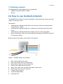
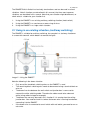
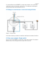
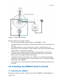
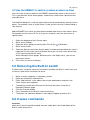
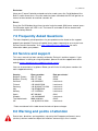
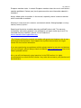
EM6557 e-Domotica Built-In Switch for Multiway
Switching
2 | ENGLISH
EM6557 e-Domotica Built-In Switch for
Multiway Switching
Table of contents
1.0 Introduction................................................................................................................. 2
1.1 Functions and features .......................................................................................... 2
1.2 Packing contents.................................................................................................... 3
2.0 How to use the Built-In Switch ................................................................................... 3
2.1 Using in an existing situation (multiway switching) ............................................... 4
2.2 Using in a new house or room and using all wires ............................................... 5
2.3 Use case example: Single switch.......................................................................... 5
3.0 Installing the EM6557 Built-In Switch ........................................................................ 6
3.1 Installing the EM6557 ............................................................................................ 6
3.2 Assigning the Built-In switch to the e-Domotica e-Centre .................................... 8
3.3 Optimise Z-wave network ...................................................................................... 9
4.0 Program your e-Centre to use the EM6557 .............................................................. 9
4.1 Add the EM6557 to an existing scene................................................................... 9
4.2 Use the EM6557 to switch on when an alarm is fired......................................... 10
5.0 Removing the Built-In switch ................................................................................... 10
6.0 Z-wave commands ................................................................................................... 10
7.0 Frequently Asked Questions.................................................................................... 11
8.0 Service and support ................................................................................................. 11
9.0 Warning and points of attention ............................................................................... 11
10.0 Warranty conditions ............................................................................................... 13
11.0 Declaration of Conformity ...................................................................................... 13
1.0 Introduction
Congratulations with the purchase of this high-quality Eminent e-Domotica product!
This product has undergone extensive testing by e-Domotica’s technical experts.
Should you experience any problems with this product, you are covered by a five-year
e-Domotica warranty. Please keep this manual and the receipt in a safe place.
1.1 Functions and features
The wireless Z-wave enabled EM6557 e-Domotica Built-In Switch, allows you to turn
on and turn off your illumination and other electrical devices by using the e-Domotica
e-Centre touchscreen, smart phone, or tablet. In combination with the e-Centre, you
can save a lot of money on your electricity account and reduce the amount of standby consumption.
The switch can be installed in any junction box, and therefore be used throughout your
entire house. The switch can also act as a repeater, by picking up the wireless signal
of other 230V e-Domotica devices and broadcast this signal forward.
3 | ENGLISH
1.2 Packing contents
The following parts need to be present in the packing:
•
EM6557 e-Domotica Built-In Switch
•
Manual
2.0 How to use the Built-In Switch
The EM6557 Built-In Switch can be connected to a lamp and to one, two or more wall
switches inside your house.
The benefits:
•
Automatically enabling the light when you enter your house, for example when
using the alarm system
•
Automatically enabling the light on a smoke alarm to find your way out of your
house
•
Automatically enabling the light on a burglary alarm to scare off intruders.
•
Manual override to switch on or off the light connected to the EM6557 using your
existing wall switches
Below a picture of all cables and functions of the device.
Image 1 – EM6557 cables and functions
1.
2.
3.
4.
5.
6.
7.
8.
9.
Blue neutral output to the lamp.
Blue neutral input wire from junction box.
Brown phase input wire from junction box.
Black switch output wire to the lamp.
White main switch wire (to switch with black switch wires).
Black switch wires for wall switch(es).
Yellow Z-wave antenna.
Include/exclude button.
Indication LED
4 | ENGLISH
The EM6557 Built-In Switch has basically two functions and can be used in several
situations. Not all situations are described in this manual, the three most common
situations are described in this manual. Note that your situation might be different, so
check what is suitable for your situation first.
1.
2.
3.
Using the EM6557 in an existing multiway switching situation (hotel switch).
Using the EM6557 in a new house or room using all wires.
Using the EM6557 in a single switch situation.
2.1 Using in an existing situation (multiway switching)
The EM6557 is suitable for multiway switching, for example in a stairway situation or
in a room with two wall switch buttons to control the lights.
Image 2 – Using the EM6557
Note the following in the above situation:
•
Only one of the two black switching wires on the EM6557 is used
•
The remaining black switching wire needs to be covered using a terminal block or
wire nut
•
The brown live wire between the wall switch and junction box is now used to
connect the white switching cable. Therefore the cable needs to be coloured
white (using adhesive tape for example)
•
The brown wire can only be used in this situation if it is coming from the ceiling
junction box. You need to check first where the brown wire is coming from before
connecting it to the EM6557
•
If the brown wire is connected to a wall switch with wall outlet, you need to run an
extra wire
5 | ENGLISH
It is also possible to use the EM6557 in a single switch situation. Just use the white
switching wire and one of the black switching wires. The other black switching wire
can be covered using a terminal block or wire nut.
2.2 Using in a new house or room and using all wires
Image 3 – Using all wires
In the above situation you need to run two black switching wires to both wall switches.
2.3 Use case example: Single switch
You can also use the EM6557 in a room with a single switch situation. For example a
bedroom with just one ceiling light and one light switch on the wall.
6 | ENGLISH
Image 4 – Single switch situation
Note the following in the above situation:
•
Only one of the two black switching wires on the EM6557 is used
•
The remaining black switching wire needs to be covered using a terminal block or
wire nut
•
The cable between the wire nut and the wall switch is coloured black in the
drawing, but can also be brown in a real situation. If you have/use a brown cable,
make sure this is not a live wire anymore
•
The brown live wire between the wall switch and junction box is now used to
connect the white switching cable. Therefore the cable needs to be coloured
black or white (using adhesive tape for example)
•
The brown wire can only be used in this situation if it is coming from the ceiling
junction box. You need to check first where the brown wire is coming from before
connecting it to the EM6557
•
If the brown wire is connected to a wall switch with wall outlet you need to run an
extra wire
3.0 Installing the EM6557 Built-In Switch
3.1 Installing the EM6557
Read the instructions carefully. Take time to install the EM6557, to avoid problems or
short circuit.
7 | ENGLISH
Warning! Take notice of the following before installing the EM6557.
If you do not have enough electrical skills, do not continue and let a certified
electrician do the job for you. Otherwise you might get injured and/or electrocuted.
If you do have enough skills, be very careful. Take notice of the following:
•
Disable the mains of your house by turning off the main switch, before you
continue. Otherwise you might get injured and/or electrocuted.
•
In some older houses the colours of the wiring can be different. In some
situations not all wires are available in the junction box or wall switch housing.
You might need to run one or more extra wires from the nearest distribution box.
•
Do not install the Built-In Switch near combustible substances or any source of
heat, e.g. fires, radiators, boilers etc.
•
Do not install the Built-In Switch facing direct sunlight, humid or dusty places.
•
Use terminal blocks or wire nuts to cover unused cables.
Eminent cannot be held liable nor responsible for any damage caused during the
installation and/or using the device afterwards.
Before you start to install, make sure you have the proper tools at hand. For example:
•
Screwdrivers
•
Wire terminals or wire nuts
•
Wire stripper
•
Adhesive tape to colour cables (if necessary)
1.
2.
3.
4.
5.
6.
7.
8.
Take the Built-In switch out of the packaging.
Check if the power is really switched off (for example by using a voltage tester).
Open the junction box where you want to install the Built-In switch. Remove the
light luminary if present.
Connect the blue neutral wire of the lamp with the left N output of the Built-In
switch and tighten the screw.
Connect the switching wire of the lamp with the LS input of the Built-In switch.
Often this wire has a black colour.
Connect the blue neutral wire of the mains with the N input (middle) of the Built-In
switch and tighten the screw.
Connect the 230v live wire of the mains with the L input of the Built-In switch.
Often this wire has a brown colour.
Check if a black switching wire or brown wire is coming from the junction box and
is running directly to the first wall switch.
a.
If so: Connect the white switching wire to the brown wire running to the
first wall switch.
Use black or white adhesive tape to colour the brown wire black or white.
This will help you to remember that the brown wire is not a live wire
anymore.
8 | ENGLISH
b.
9.
10.
11.
12.
13.
If not: Run a black switching wire to the first wall switch and connect this
to the white switching wire.
Select one of the options below depending on your situation.
a.
Multiway switching situation using all wires:
If you use two light switches on the wall: Connect one of the two the
black switching wires to the switching wire coming from the second wall
switch.
b.
Multiway Switch and Single switch situation: If you use only one light
switch on the wall: Connect a terminal block to the second non used
black switching wire from the EM6557.
Make sure all wires are fully inserted into the terminal or wire nuts.
Turn on the main switch to enable the mains again.
Test whether the device works by pressing the button on the switch. (be careful
and avoid touching the wires). The LED on the switch will be lit. The connected
device will also be turned on.
Do not close the junction box yet.
3.2 Assigning the Built-In switch to the e-Domotica eCentre
Note that you might need to enable the checkbox ‘Normal/High Power’ just below the
‘Include’ button on the ‘e-Domotica Products’ page of your e-Centre. This option is
available to be able to include devices on a greater range. For example, your e-Centre
is located in the living room and the EM6557 is located in the attic of your house.
1.
2.
3.
4.
5.
6.
7.
8.
Make sure your computer is completely started.
Open your computer’s web browser.
Enter “http://ecentre” in the address bar of your web browser and press the
‘Enter’ key on your keyboard.
The webpage of the e-Centre will be shown. If the Wizard is started, click ‘Exit
Wizard’.
Go to the ‘e-Domotica Products’ page.
Click the ‘Include’ button. The e-Centre will start to search for new e-Domotica
devices.
Press the button on your new switch three times.
A message will appear: ‘Product found’.
If the device is not found, press the ‘Exclude’ button in the e-Centre’s webpage and
then click the button on your switch. After this procedure you can add the new device
correctly.
9. Give the connected and found device a name, choose a location and click ‘Save’.
10. The switch has been added to the e-Centre. The e-Centre will now be able to
control the switch.
9 | ENGLISH
11. Put the Built-In switch into the ceiling junction box if possible. It is recommended
to disable the mains by turning off the main switch of the house when putting the
Built-In switch in the junction box.
Note that if the EM6557 does not fit into the ceiling junction box, you could also
mount/lay it inside the light luminary.
3.3 Optimise Z-wave network
It is recommended to optimise the Z-wave network now that you have included a new
230V powered device. Go back to the e-Centre webpage using a browser on your
computer. Go to the e-Domotica Products page and click on the ‘Optimise’ button. The
e-Centre will now check all wireless connections to 230V powered devices and update
this if necessary. This might take a few minutes.
4.0 Program your e-Centre to use the EM6557
Now that the EM6557 is included to your e-Centre, you can use it in several ways:
•
Add it to one or more scenes
•
To switch on when an (smoke) alarm occurs;
4.1 Add the EM6557 to an existing scene
1.
2.
3.
Go back to the e-Centre webpage as explained earlier.
Click ‘Scenes’.
‘Edit’
Select the scene you want to edit, for example ‘All on’. Click on the
button.
4. Click ‘Add’ to add a new device to this scene.
5. Select the EM6557 from the list of devices.
6. The ‘Feature’ option will show ‘Switch’ as the only option.
7. Select ‘Assign to’ from the ‘Action’ list.
8. Select ‘On’ from the ‘Value’ list.
9. Click ‘Save’ to save these setting. You will return automatically to the scene edit
page.
10. Click ‘Save’ to save the changes made to this scene. You will return
automatically to the Scenes page.
You can follow the same instructions to different scenes. For example:
•
‘All off’, in this case select ‘Off’ from the ‘Value’ list.
•
‘Invert’, in this case select ‘Invert’ from the ‘Action’ list.
Hint: If you use a smart phone or tablet to control your house as well, you can also
switch the EM6557 using one of the scenes or stand alone using Mweb. Learn more
about this in the manual of the e-Centre 2.
10 | ENGLISH
4.2 Use the EM6557 to switch on when an alarm is fired
You can let the e-Centre switch on the EM6557 automatically when an alarm occurs.
This is possible with all the alarm groups, smoke alarm, water alarm, absence alarm
and night alarm.
The benefit of doing this is that the light will be turned on automatically when the alarm
occurs. For example, when a smoke alarm is fired, you will have less trouble finding a
safe way out.
Add the EM6557 to a scene you want to be executed when one or more alarms occur.
For example use the scene ‘All On’ or if you use a special scene for each alarm or
specific alarm.
1.
2.
3.
4.
5.
6.
Open the webpage of the e-Centre again
Go to ‘Alarm Settings’.
Select the alarm group you want to edit. Click on the
‘Edit’ button.
Go to ‘Alarm events’.
Select the desired scene from the pull down list to be executed when this alarm is
triggered. For the smoke alarm and water alarm you can only select ‘Alarm fired’
as an event to execute the scene.
When editing the alarm groups ‘Absence alarm’ and ‘Night alarm’, you will see
more alarm events.
Click ‘Save’ to save the changes.
5.0 Removing the Built-In switch
In some cases it might be necessary to remove (exclude) the Built-In switch from your
e-Centre. Follow these instructions to do so:
1.
2.
3.
4.
5.
6.
7.
Make sure your computer is completely started.
Open your computer’s web browser.
Enter “http://ecentre” in the address bar of your web browser and press the
‘Enter’ key on your keyboard.
The opening screen of the Eminent e-Centre will be shown. Go to the ‘eDomotica Products’ page.
Click the ‘Exclude’ button.
Press the button on the Built-In switch three times.
The device has now been deleted, a message will appear to confirm this.
6.0 Z-wave commands
Inclusion:
Have your Z-wave Controller entered inclusion mode, press the On/off button of the
Built-In switch three times.
11 | ENGLISH
Exclusion:
Have your Z-wave Controller entered exclusion mode, press the On/off button of the
Built-In switch three times. Once the node has been excluded, the LED will go into an
interval of two seconds on and two seconds off.
Reset:
Press the On/Off button three times to enter inclusion mode. Within one second, press
On/Off button again until LED is off. The home ID and node ID will be cleared and
reset to factory default.
7.0 Frequently Asked Questions
The latest frequently asked questions for your product can be found on the support
page of your product. Eminent will update these pages frequently to assure you have
the most recent information. Visit www.e-domotica.com/support/faqs for more
information about your product.
8.0 Service and support
This users manual has been carefully written by Eminent’s technical experts. If you
have problems installing or using the product, please fill out the support form at the
website www.e-domotica.com/support/customer-service
You can also contact us by phone. Below you will find a list with phone numbers for
each supported country.
Country
Belgium (Dutch)
Belgium (French)
Denmark
Finland
Germany
Italy
Norway
Spain
Sweden
The Netherlands
UK
Phone number
070 277 286
070 277 286
+45 69918565
+35 8942415826
+49 (0)30 887 89 298
+39 0240042016
+47 21075033
807 080 042
+46 840 309985
0900-3646368
+44 (0)203 318 9998
Rate per minute*
€0.30
€0.30
Local costs
Local costs
Local costs
Local costs
Local costs
€0.41
Local costs
€0.45
Local costs
* Rates mentioned in this table do not include cell phone charges.
9.0 Warning and points of attention
Due to laws, directives and regulations set out by the European parliament, some
(wireless) devices could be subject to limitations concerning its use in certain
12 | ENGLISH
European member states. In certain European member states the use of such devices
could be prohibited. Contact your (local) government for more information about this
limitations.
Always follow up the instructions in the manual, especially where it concerns devices
which need to be assembled.
Warning: In most cases this concerns an electronic device. Wrong/improper use may
lead to (severe) injuries!
Repairing of the device should be done by qualified Eminent staff. The warranty
immediately voids when products have undergone self repair and/or by misuse. For
extended warranty conditions, please visit our website at:
www.e-domotica.com/support/warranty
*Tip: Eminent e-Domotica manuals are written with great care. However, due to new
technological developments it can happen that a printed manual does not longer
contain the most recent information.
If you are experiencing any problems with the printed manual or you can not find what
you are looking for, please always check our website www.e-domotica.com first for the
newest updated manual.
Also, you will find frequently asked questions in the FAQ section. It is highly
recommended to consult the FAQ section. Very often the answer to your questions will
be found here.
13 | ENGLISH
10.0 Warranty conditions
The five-year Eminent warranty applies to all Eminent e-Domotica products unless
mentioned otherwise before or during the moment of purchase. When having bought a
second-hand Eminent e-Domotica product the remaining period of warranty is
measured from the moment of purchase by the product’s first owner. The Eminent
warranty applies to all Eminent e-Domotica products and parts inextricably connected
to and/or mounted on the main product. Power supply adapters, batteries, antennas
and all other products not integrated in or directly connected to the main product
and/or products of which, without reasonable doubt, can be assumed that wear and
tear show a different pattern than the main product are not covered by the Eminent
warranty. Products are not covered by the Eminent warranty when subjected to
incorrect/improper use, external influences and/or when opened by parties other than
Eminent.
11.0 Declaration of Conformity
To ensure your safety and compliance of the product with the directives and laws
created by the European Commission you can obtain a copy of the Declaration of
Conformity concerning your product by sending an e-mail message to: [email protected]. You can also send a letter to:
Eminent Computer Supplies
P.O. Box 276
6160 AG Geleen
The Netherlands
Clearly state ‘Declaration of Conformity’ and the article code of the product of which
you would like to obtain a copy of the Declaration of Conformity.
EM6557 | 09-2012