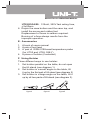
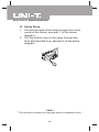
1
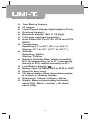
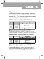
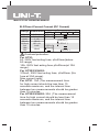
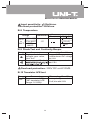
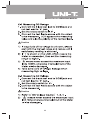
Model UT51-55: OPERATING MANUAL
Contents
A
B
C
D
E
F
G
Your Meters Feature
Specifications
Making Measurements
Maintenance
Accessories
Using Holster
Using Strap
Introduction
One kind of UNI-T brand new UT50 series
Multimeters is a 3 1/2 digit with steady function
and highly reliable hand-held measuring instrument.
The Meter uses large scale of integrated circuit
with double integrated A/D converter as its core
and has full range overload protection. The Meter
can measure DC current, AC current, DC Voltage,
AC Voltage, Resistance, Capacitance, Diode,
Temperature, Frequency and Continuity, which is
an ideal tool for users.
1
Model UT51-55: OPERATING MANUAL
Safety Rules
l The UNI-T UT50 series comply with
IEC 61010: in pollution degree 2,
overvoltage category (CAT I 1000V and
CAT II 600V) and double insulation.
Use the Meter only as specified in this
manual, otherwise the protection provided
by the Meter may be impaired.
l CAT I-For signal level, telecommunication,
electronic with small transient over voltage.
l CAT II -For local level, appliances, main
wall outlets, portable equipment.
l The meter is designed to withstand the
stated Max. voltages. If it’s not possible
to exclude without doubts that impulses,
transients, disturbance or for other reasons,
these voltages are exceeded a suitable
prescale (10:1) must be used.
l Do not operate the Meter before the cabinet
has been closed and screwed safely as
terminal can carry voltage.
l Make sure before each measurement the
Meter is set to the suitable range.
l Before using the Meter, please inspect the
cabinet and test leads for damaged insulation
or exposed metal.
l Connect the red and black test lead to the
correct measuring input jack properly.
l Do not input values over the maximum
range of each measurement to avoid damages
of the Meter.
l Do not turn the rotary function switch
during Voltage and Current measurement,
otherwise the Meter could be destroyed.
2
Model UT51-55: OPERATING MANUAL
l
l
l
l
l
l
l
l
l
l
Make sure to use new fuses with proper
rating in stead of bad fuses .
To avoid electric shock or damages, do
not apply more than 1000V between the
"COM" terminals and" "earth ground.
Use caution when working with Voltages
above 60V (DC) or 30Vrms (AC). These
Voltages pose shock hazard.
Replace the battery as soon as the battery
indicator " " appears. With a low battery,
the Meter might produce false readings
that can lead to electric shock and personal
injury.
Turn off the Meter once finished measuring,
fetch out the battery, when the meter will
not be used for long period.
Do not operate the Meter under adverse
environmental condition especially humid
area.
To avoid damages and dangerous, do not
change the circuit.
Periodically wipe the case with a damp
cloth and mild detergent. Do not use
abrasives or solvents.
The Meter is suitable for indoor use only.
International Electrical Symbols:
Low Battery
Earth Ground
Safety Rules
Double Insulated
AC
Diode
Buzzer
DC
Fuse
Dangerous Voltages
3
Model UT51-55: OPERATING MANUAL
A. Your Meters Feature
l
l
l
l
l
l
l
l
l
32 ranges.
Liquid Crystal Display, digits height is 27mm.
Overload display l.
Maximum display 1999 (3 1/2 digit).
Full range overload protection.
Auto-Power Off (For UT53, UT54 and UT55
ONLY).
Temperature:
o
o
Operating:0 C to 40 C (32 0F to 104 0F).
o
o
Storing:-10 C to 50 C (14 0F to 122 0F ).
Altitude:
Operating: 2000m
Storing: 10000m.
Relative Humidity:Max. relative humidity
80% for temperature up to 31 C decreasing
linearly to 50% relative humidity at 40 C.
Low Battery display " " .
Battery Type: 9V NEDA 1604 or 6F22 or 006P
Strap for easy carry.
Tilt stand design, three observation angles,
is in favor of reading display.
Dimension: 190mm x 88mm x 34mm.
Weight: Meter only(excluding test leads)
about 270g .Meter + holster + tilt stand
about 550g.
o
o
l
l
l
l
l
l
4
Model UT51-55: OPERATING MANUAL
B. Specifications
Accuracy is specified for one year after calibration,
o
o
at operating temperatures 23 C +/- 5 C, with relative
humidity at < 75%.Accuracy specifications take
the form of:+/- (a% readings +digits )
B-1Direct Current Voltage (DC Voltage)
Range Resolution
200mV
2V
20V
200V
1000V
Accuracy
UT51 UT 52 UT53 UT54 UT55
100µV
1mV
10mV
100mV
1V
(0.5% +1)
(0.8% +2)
Input impedance: All ranges are 10MΩ .
Overload protection: 200mV is 250VDC or AC
RMS. All other ranges is 750Vrms or 1000Vp-p.
B-2 Alternating Current Voltage (AC Voltage)
Range Resolution
200mV
2V
20V
200V
750V
100µV
1mV
10mV
100mV
1V
Accuracy
UT51 UT 52 UT53 UT54 UT55
(1.2% +3)
(0.8% +3)
(1.2% +3)
Input impedance: All ranges are 10MΩ.
Frequency: 40Hz-400Hz .
Overload protection: 200mV is 250VDC or AC
RMS. All other ranges is 750Vrms or 1000Vp-p.
Display: Average Value (RMS of Sine Wave).
5
Model UT51-55: OPERATING MANUAL
B-3 Direct Current Current (DC Current)
Range Resolution
20µA
200µA
2mA
20mA
200mA
2A
10A
20A
0.01µA
0.1 µA
1 µA
10µA
100 µA
1mA
10mA
Accuracy
UT51 UT 52 UT53 UT54 UT55
(2%+5)
(0.8%+1)
(0.8%+1)
(1.5%+1 )
(1.5%+1)
(2%+5)
(2%+5 )
Overload protection:
For UT51:
2A, 250V fast acting fuse, φ5x20mm(below
2A range)
10A, 250V fast acting fuse,φ5x20mm(at 10A
range) .
For UT52/53/54/55:
315mA, 250V fast acting fuse, φ5x20mm (No
fuse at 20A range).
Max current input :
For UT51: 10A (The measurement time
for high current should be less than 10
seconds maximum, and the interval time
between two measurements should be greater
than 15 minutes.
For UT52/53/54/55: 20A (The measurement
time for high current should be less than 15
seconds maximum, and the interval time
between two measurements should be greater
than 15 minutes.
6
Model UT51-55: OPERATING MANUAL
B-4 Alternating Current Current (AC Current)
Range Resolution
200µA
2mA
20mA
200mA
2A
10A
20A
0.1µA
1µ A
10µA
100 µA
1mA
10mA
Accuracy
UT51 UT 52 UT53 UT54 UT55
(1.8%+3)
(1%+3)
(1%+3)
(1.8%+3)
(1.8%+3)
(3%+7)
(3%+7 )
Overload protection:
For UT51:
2A, 250V fast acting fuse, φ5x20mm(below 2A
range)
10A, 250V fast acting fuse,φ5x20mm(at 10A range) .
For UT52/53/54/55:
315mA, 250V fast acting fuse,φ5x20mm (No fuse
at 20A range).
Max current input :
For UT51: 10A (The measurement time for high
current should be less than 10 seconds maximum,
and the interval time between two measurements
should be greater than 15 minutes.
For UT52/53/54/55: 20A (The measurement time
for high current should be less than 15 seconds
maximum, and the interval time between two
measurements should be greater than 15 minutes.
Measuring voltage drop: Full range is 200mV.
Display: Average Value (RMS of Sine Wave ) .
7
Model UT51-55: OPERATING MANUAL
B-5 Resistance
Range Resolution
200Ω
2KΩ
20KΩ
200KΩ
2MΩ
20MΩ
200MΩ
0.1Ω
1Ω
10Ω
100Ω
1KΩ
10KΩ
100KΩ
Accuracy
UT51 UT 52 UT53 UT54 UT55
(0.8% +3)
(0.8% +1)
(1% +2)
[5%(-10) +10]
Voltage at open circuit: 700mV (200MΩ range,
open circuit voltage around 3V) .
Overload protection: All ranges 250VDC or AC
RMS .
Caution: At 200MΩ range, as test lead is short
circuit the LCD display 10 digits is normal, deduct
the 10 digits from the measured reading during
measuring.
B- 6 Capacitance
Range Resolution
2nF
20nF
200nF
2µF
20µF
Accuracy
UT51 UT 52 UT53 UT54 UT55
1pF
10pF
100pF
1nF
10nF
(4% +3)
Testing signal: around 400Hz 40mVrms
B-7 Frequency
Range Resolution
2kHz
20kHz
1Hz
10Hz
Accuracy
UT51 UT52 UT53 UT54 UT55
(2%+5)
(1.5%+5)
8
Model UT51-55: OPERATING MANUAL
Input sensitivity: 100mVrms.
Overload protection: 250Vrms.
B-8 Temperature
Range
o
Resolution
o
o
-20 C to 0 C
-20 C o
o
to 0 C to 400 C
o
1000 C 400oCto
o
1000 C
o
1C
Accuracy
UT51,52,53 UT53 UT55
(5%+3)
(1%+3)
2%
B-9 Diode Test and Continuity Beeper
Range
Measuring Condition
Comment
Display diode forward- Forward DC current abt
1mABackward DC voltage
voltage near value,
abt 2.8V
Unit “ mV”
Voltage at open circuit
abt 2.8V
“ ”
Overload protection: 250V DC or AC RMS.
B-10 Transistor hFE test
Range
hFE
Measuring Condition
Comment
Can measure NPN or Basic polarity current abt
PNP transistor hFE.
10µA,Vce abt 2.8V
Range: 0-1000β
9
Model UT51-55: OPERATING MANUAL
C. Making Measurements
“
1
3
5
7
“
”
2
Capacitance jack
Temperature jack
Transistor jack
”
On/Off Switch
Liquid Crystal Display
Rotary switch
Input jack
10
4
6
Model UT51-55: OPERATING MANUAL
“
”
“
”
“ ”
“
”
Caution
“ ”
“
”
“
”
“
”
Caution
“
“
”
”
11
Model UT51-55: OPERATING MANUAL
“
”
“
”
“ ”
“
”
Caution
“ ”
“
”
“ ”
“
”
Caution
1) Please refer to DC Current Caution 1, 2, 3.
12
Model UT51-55: OPERATING MANUAL
C-5 Measuring Resistance
“
”
“ ”
“ ”
Caution
“ ”
“ ”
C-6 Measuring Capacitance
Before measuring capacitance, remember it takes
time for zeroing when changing ranges. Floating
reading does not effect accuracy.
1) To avoid damage of the Meter or the equipment
under testing, disconnect circuit powers and
discharge capacitors before measuring
capacitance.
2) Connect capacitor to the capacitance jack.
3) Stabilizing reading takes some time when
measuring high capacitance.
4) Unit: 1pF=10-6µF, 1nF = 10-3µF
13
Model UT51-55: OPERATING MANUAL
C-7 Measuring Frequency
“
“
”
”
“
”
“
“
”
“
14
”
”
Model UT51-55: OPERATING MANUAL
D. Maintenance
I. General Service
“
” “ ”“
15
”
“
”
Model UT51-55: OPERATING MANUAL
2. Turn the Meter power OFF
3. Remove the holster from the Meter.
4. Remove rubber feet and screws from the case
bottom, and separate the case bottom from
the case top.
5. Remove the battery from the battery compartment.
6. Replace the battery with a new 9V battery
(NEDA 1604 or 6F22 or 006P).
7. Rejoin the case bottom and case top, and install
the screws and rubber feet.
III.Replacing the Fuses
Caution
To avoid electrical shock or arc blast, or personal
injury or damage to the Meter, use specified
fuses ONLY in accordance with the following
procedure.
To replace the Meter’s fuse:
1. Disconnect the connection between the testing
leads and the circuit under test, and remove
the testing leads away from the input terminals
of the Meter.
2. Turn the Meter power OFF.
3. Remove the rubber feet and screws from the
case bottom, and separate the case bottom
from the case top.
4. Remove the fuse by gently prying one end loose,
and then take out the fuse from its bracket.
5. Install ONLY replacement fuses with the
identical type and specification as follows and
make sure the fuse is fixed firmly in the bracket.
UT51: 2A, 250V fast acting fuse,φ5x20mm
(below 2A range)
10A, 250V fast acting fuse,φ5x20mm (at 10A
range)
16
Model UT51-55: OPERATING MANUAL
UT52/53/54/55: 315mA, 250V fast acting fuse,
φ 5x20mm
6. Rejoin the case bottom and the case top, and
install the screw and rubber feet
Replacement of fuses is seldom required.
Burning of a fuse always results from the
improper operation.
E. Accessories
1. A book of users manual
2. A pair of test lead
3. A pair of WRN-01B bread temperature probe
(for UT53 and UT55 ONLY)
4. A piece of holster (if selected)
F. Using Holster
Three different ways to use holster:
1. Set holster parallel on the table, do not open
the tilt stand (see diagram 1).
2. Set holster in a small angle on the table, tilt
it up by the first part of tilt stand (see diagram 2)
3. Set holster in a large angle on the table, tilt it
up by all two parts of tilt stand (see diagram 3).
figure1
figure2
17
figure3
Model UT51-55: OPERATING MANUAL
G. Using Strap
1. Put the front end of the strap through the round
metal of the Meter, see part 1 of the below
diagram.
2. Put the bottom end of the strap through the
front part and tide it up, see part 2 of the below
diagram.
~ END ~
* The manual is subject to changes without separate notice. *
18
Model UT51-55: OPERATING MANUAL
19
Model UT51-55: OPERATING MANUAL
Manufacturer: UNI-TREND TECHNOLOGY(DONG GUAN)LIMITED
Address: Dong Fang Da Dao, Bei Shan Dong Fang Industrial
Development District, Hu Men Town, Dong Guan City,
Guang Dong Province, China
Headquarters: Uni-Trend International Limited
Address: Rm901, 9/F, Nanyang Plaza 57 Hung To Road
Kwun Tong Kowloon, Hong Kong
Tel: (852) 2950 9168
Fax: (852) 2950 9303
Email: [email protected]
http://www.uni-trend.com
20