1
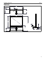
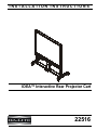
INSTALLATION INSTRUCTIONS
Instrucciones de instalación
Installationsanleitung
Instruções de Instalação
Istruzioni di installazione
Installatie-instructies
Instructions d´installation
IDEA™ Interactive Rear Projector Cart
Spanish Product Description
German Product Description
Portuguese Product Description
Italian Product Description
Dutch Product Description
French Product Description
22516
22516
Installation Instructions
DISCLAIMER
Milestone AV Technologies and its affiliated corporations and
subsidiaries (collectively "Milestone"), intend to make this
manual accurate and complete. However, Milestone makes no
claim that the information contained herein covers all details,
conditions or variations, nor does it provide for every possible
contingency in connection with the installation or use of this
product. The information contained in this document is subject
to change without notice or obligation of any kind. Milestone
makes no representation of warranty, expressed or implied,
regarding the information contained herein. Milestone assumes
no responsibility for accuracy, completeness or sufficiency of
the information contained in this document.
WARNING: Use this mounting system only for its intended
use as described in these instructions. Do not use
attachments not recommended by the manufacturer.
WARNING: Never operate this mounting system if it is
damaged. Return the mounting system to a service center for
examination and repair.
WARNING: Do not use this product outdoors.
--SAVE THESE INSTRUCTIONS-Da-Lite® is a registered trademark of Milestone AV
Technologies. All rights reserved.
eBeam™ Interactive System Requirements
The eBeam™ Interactive system works with standard
projectors and Windows® and Macintosh® computers.
IMPORTANT SAFETY INSTRUCTIONS
WARNING: A WARNING alerts you to the possibility of
serious injury or death if you do not follow the instructions.
IMPORTANT ! : After adding batteries to the stylus (FF),
tighten the cap only to the point of being fingertip-tight.
Overtightening cap may cause the stylus to stop
transmitting signals.
Minimum System Requirements
•
damage or destruction of equipment if you do not follow the
corresponding instructions.
WARNING: Failure to read, thoroughly understand, and
follow all instructions can result in serious personal injury,
damage to equipment, or voiding of factory warranty! It is the
installer’s responsibility to make sure all components are
properly assembled and installed using the instructions
provided.
WARNING: Failure to provide adequate structural strength
for this component can result in serious personal injury or
damage to equipment! It is the installer’s responsibility to
make sure the structure to which this component is attached
can support five times the combined weight of all equipment.
Reinforce the structure as required before installing the
component.
Windows® System
Compatible PC with Pentium™ II 400 MHz+
processor and 256 MB RAM
•
Windows 2000, XP, Server 2003, Vista, or 7
•
30 MB available hard drive space
•
Available USB port
Macintosh® System
•
Power PC®/Intel™ 1.42 GHz+ processor and 1G
RAM
•
Mac OS X 10.5 through 10.6
•
25 MB available hard drive space
•
Available USB port
•
CAUTION: A CAUTION alerts you to the possibility of
•
Active Capture Area Size
•
•
The maximum active capture area supported is:
4 ft x 7 ft or up to 94 inches diagonal measure.
The minimum active capture area supported is:
1.7 ft x 1.1 ft.
Connection Requirement
•
The interactive mount includes a USB cable.
Screen Recording Requirements
2
WARNING: Exceeding the weight capacity can result in
(Currently available only on Windows platform.)
serious personal injury or damage to equipment! It is the
installer’s responsibility to make sure the combined weight of
all components located on the projector boom arm do not
exceed 25 lbs (11.34 kg).
•
•
Pentium™ IV processor
1.4GHz, with 512MB RAM
Installation Instructions
22516
DIMENSIONS
74.8
2.9
11.2
31.5
CENTER OF PROJECTOR
TO SCREEN
21.2 MAX
69.3
55.1
79.0
82.9 MAX
77.9 MID
72.9 MIN
16.6
5.0
34.1 MAX
29.1 MID
24.1 MIN
(3 POSITIONS)
37.4
27.0
1.5
4.3
7.1
3
22516
Installation Instructions
LEGEND
4
Tighten Fastener
Pencil Mark
Apretar elemento de fijación
Marcar con lápiz
Befestigungsteil festziehen
Stiftmarkierung
Apertar fixador
Marcar com lápis
Serrare il fissaggio
Segno a matita
Bevestiging vastdraaien
Potloodmerkteken
Serrez les fixations
Marquage au crayon
Loosen Fastener
Drill Hole
Aflojar elemento de fijación
Perforar
Befestigungsteil lösen
Bohrloch
Desapertar fixador
Fazer furo
Allentare il fissaggio
Praticare un foro
Bevestiging losdraaien
Gat boren
Desserrez les fixations
Percez un trou
Phillips Screwdriver
Adjust
Destornillador Phillips
Ajustar
Kreuzschlitzschraubendreher
Einstellen
Chave de fendas Phillips
Ajustar
Cacciavite a stella
Regolare
Kruiskopschroevendraaier
Afstellen
Tournevis à pointe cruciforme
Ajuster
Open-Ended Wrench
Remove
Llave de boca
Quitar
Gabelschlüssel
Entfernen
Chave de bocas
Remover
Chiave a punte aperte
Rimuovere
Steeksleutel
Verwijderen
Clé à fourche
Retirez
By Hand
Optional
A mano
Opcional
Von Hand
Optional
Com a mão
Opcional
A mano
Opzionale
Met de hand
Optie
À la main
En option
Hex-Head Wrench
Security Wrench
Llave de cabeza hexagonal
Llave de seguridad
Sechskantschlüssel
Sicherheitsschlüssel
Chave de cabeça sextavada
Chave de segurança
Chiave esagonale
Chiave di sicurezza
Zeskantsleutel
Veiligheidssleutel
Clé à tête hexagonale
Clé de sécurité
Installation Instructions
22516
TOOLS REQUIRED FOR INSTALLATION
#2
3/16" (included)
5/32" (included)
1/2" (12.7mm)
PARTS
C (1)
[projector boom arm]
B (1)
[leg and cross bar assembly]
A (1)
[IDEA™ screen]
EBeam Interactive Kit (1)
G (1)
D (1)
[screen tray and cross assembly] [height-adjust beam]
Quick Start
Guide
H (2)
[side column]
FF (1)
[stylus]
J (1)
[right column K (1)
extender] [left column
extender]
E (1)
[inner top frame]
GG (1)
[interactive
software]
HH (1)
[AAA battery]
L (1)
[top telescoping shroud]
M (1)
[base telescoping shroud]
F (1)
[outer top frame]
JJ (4)
[stylus
replacement
tips]
KK (1)
[stylus
wrist strap
kit]
R (2)
[knob]
W (8)
5/16-18 x 2 1/2"
Interactive
Software
Guide
CC (6)
[cable tie]
X (4)
1/4-20 x 2 1/2"
DD (1)
3/16"
Y (10)
5/16"
EE (1)
5/32"
T (6)
#10-24"
Z (4)
1/4"
P (4)
[cable clip]
N (2)
[stud strip]
U (2)
5/16-18"
V (2)
#10-24"
AA (2)
BB (14)
1/4-20 x 3/8" #10-24 x 3/8"
FF (1)
[dry-erase marker kit]
5
22516
Installation Instructions
Assembly And Installation
Cart Assembly
1.
Use eight 5/16-18 x 2 1/2" button head cap screws (W) and
eight 5/16" washers (Y) to secure two side columns (H) to
leg and cross bar assembly (B). (See Figure 1)
2
(BB) x 4
4
(H) x 2
2
(B)
(Y) x 8
Figure 2
1
(W) x 8
5.
Hang screen tray and cross assembly (D) onto studs on
column extenders (J and K). (See Figure 3)
6.
Use four #10-24 Phillips pan machine screws (BB) to
secure screen tray and cross assembly (D) to column
extenders (J and K). (See Figure 3)
(rear view)
5 studs on
extenders
Figure 1
IMPORTANT ! : If using side columns (H) for cable
management, install cable clips (P) to side columns prior
to installing column extenders to side columns. Square
nuts (V) will not be able to slide along the full channels if
extenders are already attached. See Cable Management
section for side column cable management installation
instructions.
2.
Slide two column extenders (J and K) over side columns
(H). (See Figure 2)
6
NOTE: Make sure right column extender (J) is installed over
right column and left column extender (K) is installed
over left column.
3.
Line up holes on extenders with holes on side columns at
desired mounting height. (See Figure 2)
IMPORTANT ! : Setting the mounting height at this point
is much easier than adjusting it after the screen has been
installed. Make sure column extenders are set at desired
height prior to installing screws in the next step.
4.
6
Use two #10-24 x 3/8" Phillips pan machine screws (BB) to
secure each column extender (J and K) to corresponding
side column (H). (See Figure 2)
Figure 3
(BB) x 4
Installation Instructions
22516
7.
Slide height-adjust beam (G) inside top telescoping shroud
(L) in preparation for installation to cart. (See Figure 4)
8.
Install top telescoping shroud (L) with height-adjust beam
(G) into opening of screen tray and cross assembly (D).
(See Figure 4)
9.
(rear view)
(N) x 2
10
(T) x 4
Use four 1/4-20 x 2 1/2" button head cap screws (X) and
four 1/4" washers (Z) to secure height-adjust beam (G) and
base telescoping shroud (M) to cross bar assembly (B).
(See Figure 4)
11
(rear view)
(D)
(L)
8
(B)
(G)
7
Figure 5
(M)
12. Use two knobs (R) to attach projector boom arm (C) to
height-adjust beam by screwing them onto upper stud of
each stud strip (N). (See Figure 6)
13. Loosely screw two 5/16" nuts (U) and two 5/16" (Y) washers
onto lower stud of each stud strip (N). (See Figure 6)
IMPORTANT ! : Do NOT fully tighten nuts for easy
height-adjustment capability.
(Z) x 4
(rear view)
9
(X) x 4
12
(R) x 2
(N) x 2
Figure 4
10. Use four #10-24 hex nuts to secure top telescoping shroud
(L) to screen tray and cross assembly (D). (See Figure 5)
11. Slide two stud strips (N) into channels on height-adjust
beam (G). (See Figure 5)
(Y) x 2
(C)
13
(U) x 2
Figure 6
7
22516
Installation Instructions
IDEA™ Screen Installation
1.
CAUTION: Do NOT overtighten screws or screen may be
Slide inner top frame (E) into outer top frame (F), making
sure screws on inner frame are aligned with holes on outer
top frame. (See Figure 7)
damaged!
(rear view)
(BB) x 4
5
(E)
6
(F)
Figure 7
Figure 9
CAUTION: Do NOT touch back of IDEA™ screen during
installation or projection surface may be damaged!
2.
Carefully slide IDEA™ screen into cart, inserting it into the
grooves at the back of the column extenders (J and K) and
making sure it is fully seated in the top groove of the screen
tray and cross assembly (D). (See Figure 8)
3.
While holding the screen in place, set inner and outer top
frames (E and F) on top of screen. (See Figure 8)
2
3
Projector Installation
CAUTION: Make sure knobs (R) are tightened prior to
installing projector to projector boom arm! Boom arm may fall
off if knobs are not secured.
1.
Attach SSMU interface bracket to projector following SSMU
installation instructions.
2.
Lower projector and attached SSMU interface onto RSM
plate on projector boom arm. (See Figure 10)
3.
Slide projector with SSMU onto mounting slots in RSM plate
until mounting buttons are seated against the back of
mounting slots. (See Figure 10)
4.
Move locking lever on RSM to "locked" position. (See
Figure 10)
5.
Insert key into lock and turn to secure projector to mount.
2
3
5
2
Figure 8
4.
5.
8
Use four #10-24 x 3/8" Phillips machine pan screws (BB) to
secure outer top frame (F) to column extenders (J and K).
(See Figure 9)
Turn seven screws pre-installed on inner top frame (E)
counter-clockwise until screen is tightly secured. (See
Figure 9)
4
Figure 10
Installation Instructions
22516
Cable Management
From Projector
On Side Columns (Monitor Arm Accessory)
4.
1.
Slide two #10-24 square nuts (V) into side columns (H) prior
to attaching column extenders (J and K).
2.
Install two #10-24 x 3/8" Phillips pan machine screws (BB)
through two cable clips (P) and into #10-24 square nuts (V).
(See Figure 11)
Use two 1/4-20 x 3/8" Phillips pan machine screws (AA) to
secure two cable clips (P) along base of cross bar
assembly. (See Figure 13)
1 (V) x 2
(P) x 2
2
(BB) x 2
(P) x 2
(AA) x 2
4
Figure 13
Figure 11
3.
5.
(Optional) Route cables from projector through boom arm
channel down to cross bar assembly base. (See Figure 14)
6.
Route cables through cable clips and use cable ties (Q) to
secure cables along cross bar assembly base. (See
Figure 14)
Route cables through cable clips and use cable ties (CC) to
secure cables along side column. (See Figure 12)
5
cable (example)
cable (example)
(CC) x 2
(CC) x 2
6
6
Figure 12
Figure 14
9
22516
Installation Instructions
Adjustments
Projector Location Adjustments
Height Adjustments
IDEA™ Screen
Boom Arm Position
1.
Loosen screws holding base bracket to projector arm. (See
Figure 16)
2.
Slide projector along projector arm until desired projector
position is reached. (See Figure 16)
3.
Tighten screws holding base bracket to projector arm. (See
Figure 16)
CAUTION: Make sure top frame is supported prior to
removing screws to prevent screen from falling during heightadjustment!
1.
Remove two screws connecting column extenders (J and K)
to each side column (H). (See Figure 15)
2.
Adjust height of screen to desired height and line up holes
on column extenders with holes on side columns. (See
Figure 15)
3.
Use two removed screws to reattach each column extender
to each side column at desired height. (See Figure 15)
1
3
2
1
3
2
5
2
2
4
5
(projector not shown
for clarity)
5
6
Figure 16
Lateral Shift
(projector not shown
for clarity)
4
5
Loosen two screws on either side of the lateral shift plate.
(See Figure 16)
5.
Carefully slide projector laterally until desired lateral
position is reached. (See Figure 16)
6
Figure 15
Projector
4.
Loosen two knobs (R) securing projector boom arm to
height-adjust beam. (See Figure 15)
5.
Adjust boom arm height to desired height. (See Figure 15)
6.
Tighten two knobs (R) to see arm at desired position. (See
Figure 15)
10
4.
CAUTION: Do not slide projector too far to either side of
lateral shift plate or projector may slide off plate!
6.
Tighten two screws on either side of lateral shift plate that
were loosened in Step 4. (See Figure 16)
Installation Instructions
22516
Pitch Adjustment
7.
Loosen Pitch adjustment locking screw. (See Figure 17)
8.
Turn Pitch micro-adjustment screw right or left until image is
properly aligned on screen. (See Figure 17)
9.
Tighten Pitch adjustment locking screw. (See Figure 17)
11
8
10
12
(projector not shown
for clarity)
11
Figure 18
8
Roll Adjustment
13. Loosen Roll adjustment locking screw. (See Figure 19)
7
9
14. Turn Roll micro-adjustment screw right or left until image is
properly aligned on screen. (See Figure 19)
(projector not shown
for clarity)
15. Tighten Roll adjustment locking screw. (See Figure 19)
Figure 17
Yaw Adjustment
10. Loosen Yaw adjustment locking screw. (See Figure 18)
11. Turn Yaw micro-adjustment screw right or left until image is
properly aligned on screen. (See Figure 18)
12. Tighten Yaw adjustment locking screw. (See Figure 18)
8
8
7
9
(projector not shown
for clarity)
Figure 19
11
22516
Installation Instructions
Da-Lite Screen Company, LLC
8800-002223 Rev02
09/12
3100 North Detroit Street
P.O. Box 137
Warsaw, IN 46581-0137
Phone: 800.267.8101
Toll Free: 574.267.3737
Fax: 574.267.7804
Toll Free Fax: 877.325.4832
www.da-lite.com
[email protected]