1
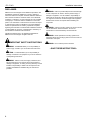
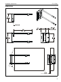
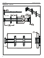
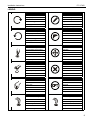
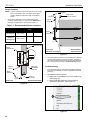
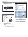
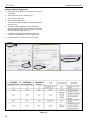
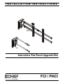
INSTALLATION INSTRUCTIONS
PACI
FCI
Interactive Flat Panel Upgrade Kits
Spanish Product Description
German Product Description
Portuguese Product Description
Italian Product Description
Dutch Product Description
French Product Description
FCI / PACI
FCI / PACI
Installation Instructions
DISCLAIMER
Milestone AV Technologies and its affiliated corporations and
subsidiaries (collectively "Milestone"), intend to make this
manual accurate and complete. However, Milestone makes no
claim that the information contained herein covers all details,
conditions or variations, nor does it provide for every possible
contingency in connection with the installation or use of this
product. The information contained in this document is subject
to change without notice or obligation of any kind. Milestone
makes no representation of warranty, expressed or implied,
regarding the information contained herein. Milestone assumes
no responsibility for accuracy, completeness or sufficiency of
the information contained in this document.
Chief® and ClickConnect™ are registered trademarks of
Milestone AV Technologies. All rights reserved.
WARNING: Failure to provide adequate structural strength
for this component can result in serious personal injury or
damage to equipment! It is the installer’s responsibility to
make sure the structure to which this component is attached
can support five times the combined weight of all equipment.
Reinforce the structure as required before installing the
component.
WARNING: Use this mounting system only for its intended
use as described in these instructions. Do not use
attachments not recommended by the manufacturer.
WARNING: Never operate this mounting system if it is
damaged. Return the mounting system to a service center for
examination and repair.
IMPORTANT SAFETY INSTRUCTIONS
WARNING: Do not use this product outdoors.
WARNING: A WARNING alerts you to the possibility of
serious injury or death if you do not follow the instructions.
CAUTION: A CAUTION alerts you to the possibility of
damage or destruction of equipment if you do not follow the
corresponding instructions.
WARNING: Failure to read, thoroughly understand, and
follow all instructions can result in serious personal injury,
damage to equipment, or voiding of factory warranty! It is the
installer’s responsibility to make sure all components are
properly assembled and installed using the instructions
provided.
2
--SAVE THESE INSTRUCTIONS--
Installation Instructions
FCI / PACI
DIMENSIONS
FCI
140°
COVERAGE
ANGLE
FOR BEST RESULTS: SLIDE THE SENSOR OUT UNTIL THE CORNERS OF THE TV ARE WITHIN THE COVERAGE AREA
0.50
12.7
RECOMMENDED SPACING
3
FCI / PACI
Installation Instructions
DIMENSIONS - continued
PACI
14.00
355.7
0.50
12.7
RECOMMENDED
SPACING
140°
SENSOR
COVERAGE
SLIDE SENSOR SO THAT CORNERS OF TV ARE INSIDE COVERAGE AREA
LIKE SHOWN ABOVE.
4
Installation Instructions
FCI / PACI
LEGEND
Tighten Fastener
Pencil Mark
Apretar elemento de fijación
Marcar con lápiz
Befestigungsteil festziehen
Stiftmarkierung
Apertar fixador
Marcar com lápis
Serrare il fissaggio
Segno a matita
Bevestiging vastdraaien
Potloodmerkteken
Serrez les fixations
Marquage au crayon
Loosen Fastener
Drill Hole
Aflojar elemento de fijación
Perforar
Befestigungsteil lösen
Bohrloch
Desapertar fixador
Fazer furo
Allentare il fissaggio
Praticare un foro
Bevestiging losdraaien
Gat boren
Desserrez les fixations
Percez un trou
Phillips Screwdriver
Adjust
Destornillador Phillips
Ajustar
Kreuzschlitzschraubendreher
Einstellen
Chave de fendas Phillips
Ajustar
Cacciavite a stella
Regolare
Kruiskopschroevendraaier
Afstellen
Tournevis à pointe cruciforme
Ajuster
Open-Ended Wrench
Remove
Llave de boca
Quitar
Gabelschlüssel
Entfernen
Chave de bocas
Remover
Chiave a punte aperte
Rimuovere
Steeksleutel
Verwijderen
Clé à fourche
Retirez
By Hand
Optional
A mano
Opcional
Von Hand
Optional
Com a mão
Opcional
A mano
Opzionale
Met de hand
Optie
À la main
En option
Hex-Head Wrench
Security Wrench
Llave de cabeza hexagonal
Llave de seguridad
Sechskantschlüssel
Sicherheitsschlüssel
Chave de cabeça sextavada
Chave de segurança
Chiave esagonale
Chiave di sicurezza
Zeskantsleutel
Veiligheidssleutel
Clé à tête hexagonale
Clé de sécurité
5
FCI / PACI
Installation Instructions
TOOLS REQUIRED FOR INSTALLATION
1/8"
(includedboth models)
3/16"
(included FCI only)
PARTS
FCI Only
A (2)
ClickConnect 10-24 x 3/8"
B (2)
#10
Interactive Hardware
Kit (PACI Only)
D (1)
[FCI 3"-5"
extension
bracket]
E (2)
[Interactive
bar assembly]
C (1)
1/8"
PACI Only
H (1)
1/8"
D (1)
[PACI 3"-5"
extension
bracket]
G (2)
5/16 x 5/8"
F (1)
[Sensor assembly]
J (1)
3/16"
K (1) - Chief Interactive Kit (Both FCI / PACI models)
F (1)
[Sensor assembly]
KA (1)
[Stylus replacement
tip kit - 4 tips]
E (1)
[ClickConnect
interactive
assembly]
KD (1)
[AAA battery]
KC (1)
[Interactive
software]
KF (1)
[Stylus wrist
strap kit]
6
KB (1)
[Stylus]
KE (1)
[Quick start
guide]
KG (1)
[Interactive
USB cable]
Installation Instructions
FCI / PACI
PRE-INSTALLATION INFORMATION
Compatibility
(F)
An up-to-date list of the flat panel TV models recommended for
use with Chief’s FCI and PACI interactive kits can be found at
www.chiefmfg.com/Interactive-Mounts. The recommended flat
panel models all have the same display requirements:
•
•
•
(D)
Rigid front panel to protect LCD from wear
40" to 55" LED-backlit LCD to reduce interference
with the sensor due to excessive heat
Bezel depth of 8mm (0.33") or less for optimal
performance in flat panel display corners.
IMPORTANT ! : The following procedure assumes that
the appropriate Chief flat panel mount (not included) has
been properly installed following instructions provided
with the mount.
x2
3
3
FCI / PACI INSTALLATION
IMPORTANT ! : Determine depth (thickness) of flat panel
TV. If the TV is MORE than 3" in depth (76.2mm),
proceed to Step 1. If the TV is LESS than 3" in depth,
proceed to either Complete FCI Installation or Complete
PACI Installation section, as appropriate.
1.
Remove and save two button head cap screws and two
washers from back of sensor assembly (F). (See Figure 1)
(F)
1
x2
Figure 2
NOTE: Proceed to either Complete FCI Installation or
Complete PACI Installation section, as appropriate.
Complete FCI Installation
1.
Remove TV from mount.
2.
Remove end caps from flat panel mount. (See Figure 3)
2
x 2 end caps
Example of
mount
2
Extender
bracket
Figure 1
2.
Remove extender bracket from back of sensor assembly
(F). (See Figure 1)
3.
Attach 3"-5" extension bracket (D) to sensor assembly (F)
using two button head cap screws and two washers
removed in Step 1. (See Figure 2)
Figure 3
7
FCI / PACI
3.
Installation Instructions
Insert interactive bar assembly (E) into flat panel mount,
turning bars until tightened into flat panel mount. (See
Figure 4)
(back view)
3
(E)
Flat panel
mount
(E)
3
3
2
3
4
(front view)
Figure 4
4.
Fasten sensor assembly (F) to bars (E) using two 5/16 x 5/8"
button head cap screws (G). (See Figure 5)
4
Figure 6
5.
Align ClickConnect assembly (E) with the mount, aligning
four mounting buttons on assembly with four mounting
holes in mount. (See Figure 7)
(G) x 2
Example of
mount
5
(E)
6
(F)
Figure 5
5.
Re-attach flat panel TV following instructions contained with
mount.
6.
Proceed to Connecting FCI/PACI section.
(E)
Figure 7
Complete PACI Installation
1.
Remove TV from mount.
2.
Loosen four button head cap screws on back of
ClickConnect interactive assembly (E). (See Figure 6)
3.
Adjust interactive assembly (E) to proper extension. (See
Figure 6)
4.
Tighten four button head cap screws on back of
ClickConnect assembly (E). (See Figure 6)
8
6.
Lower ClickConnect assembly (E) into place listening for
audible "click" to ensure recessed area of mounting buttons
are properly seated in lower area of mounting holes and
ClickConnect mechanism has engaged. (See Figure 7) and
(See Figure 8)
WARNING: IMPROPER INSTALLATION CAN LEAD TO
DISPLAY FALLING CAUSING SERIOUS PERSONAL
INJURY OR DAMAGE TO EQUIPMENT! Ensure mounting
buttons are completely engaged in mounting holes.
Installation Instructions
FCI / PACI
Holes are provided in the faceplate for use with a padlock or
similar locking device, if desired. In addition, the pin and nut may
be removed from the upper holes and moved to the lower holes
for use as a more permanent locking device. (See Figure 8)
To use as a more
permanent lock, remove
pin and nuts and move
to lower holes.
5
CONNECTING FCI/PACI
NOTE: Follow instructions in the Quick Start Guide (KE).
IMPORTANT ! : After adding battery (KD) to the stylus
(KB), tighten the cap only to the point of being fingertiptight. Overtightening cap may cause the stylus to stop
transmitting signals.
1.
Connect flat panel TV to computer.
2.
Connect USB cord (KG) from cartridge in sensor assembly
(F) to computer USB port.
3.
Insert interactive software CD (KC) into computer, and
follow start-up and operating instructions.
Minimum System Requirements for FCI/PACI
6
•
Windows® System
Compatible PC with Pentium™ II 400 MHz+
processor and 256 MB RAM
•
Windows 2000, XP, Server 2003, Vista, or 7
•
30 MB available hard drive space
•
Available USB port
Macintosh® System
•
Power PC®/Intel™ 1.42 GHz+ processor and 1G
RAM
•
Mac OS X 10.5 through 10.6
•
25 MB available hard drive space
•
Available USB port
•
•
A padlock or bolt may
be placed through latch holes
Figure 8
7.
Fasten sensor assembly (F) to ClickConnect assembly (E)
using two 10-24 x 3/8" button head cap screws (A) and two
#10 flat washers (B). (See Figure 9)
Connection Requirement
•
The FCI/PACI includes a USB cable.
Screen Recording Requirements
(Currently available only on Windows platform.)
7
(A) x 2
•
•
(B) x 2
Pentium™ IV processor
1.4GHz, with 512MB RAM
Placement Tips
NOTE: See DIMENSIONS drawing for TV/sensor assembly
(E)
placement information.
•
•
The corners of the TV should be positioned within the
fan area extending from the sensor assembly. This fan
area should not exceed 140°.
Do not put sticky notes, hanging paper, cables, outlets,
or other items inside the capture area.
(F)
Figure 9
8.
Re-attach flat panel TV following instructions contained with
mount.
9.
Proceed to Connecting FCI/PACI section.
9
FCI / PACI
Installation Instructions
Sensor Location
NOTE: The FCI and PACI may be mounted to the left or right
side of a flat panel screen. The green sensor light
needs to always be oriented so that it is closest to
screen.
1.
3"
[76.2mm]
Move sensor assembly to the recommended sensor
locations noted in Table 1-1, and shown in Dimensions
drawings and (See Figure 10) and (See Figure 11).
Lateral extension
dimension
Edge of flat
panel TV screen
Face of
sensor
Table 1-1: Recommended Sensor Locations
Measurement
Description
Operational Recommended
Range
Depth
Edge of sensor to
(See Figure 10)
front of screen
Lateral
Face of sensor to
Extension
edge of screen
0" - 1"
1/2"
>3"
3"
Sensor
assembly (F)
(See Figure 11)
140°
COVERAGE
ANGLE
Flat panel TV
Sensor
assembly (F)
(Front view)
(FCI shown as example)
Recommended
lateral extension
Figure 11
2.
Depth may
be adjusted
along slot
Edge of
sensor
Troubleshooting
1.
Fully extend FCI/PACI in both lateral and depth directions
so that sensor assembly is as far as possible from the flat
panel TV.
2.
Recalibrate the eBeam software.
Depth
dimension
Front of
TV screen
0.50"
[12.7mm]
(Side view)
Recommended depth
The Chief interactive sensor may act differently in different
environmental settings. If placing the sensor assembly in
the recommended locations does not allow the interactive
kit to work properly, proceed to Troubleshooting section.
a. Right click on the eBeam icon on the system tray.
(See Figure 12)
b. Select Calibrate Interactive Area and follow
calibration instructions. (See Figure 12)
Figure 10
2b
Figure 12
10
Installation Instructions
3.
FCI / PACI
Perform the grid test to see if there are any inconsistencies.
a. Open eBeam software (See Figure 13)
FAILED grid test
Distorted annotation
lines
a
PASSED grid test
Figure 13
b. Go to Full Screen view (See Figure 14)
b
c
Figure 15
5.
If the grid test has failed, gradually move the sensor
assembly in 1/2" increments in both the depth and lateral
extension ranges until the grid test is passed.
6.
If the interactive area is not responding precisely after the
grid tests, proceed to Checking System Diagnostics
section.
Figure 14
c. Select Pen Mode (See Figure 14)
d. Draw a grid on the screen with lines approximately
2" apart.
•
A failed grid test will show distorted annotation
lines. (See Figure 15)
•
A passed grid test will show no broken or distorted
annotation lines. (See Figure 15)
11
FCI / PACI
Installation Instructions
Checking System Diagnostics
1.
Right click on the E-Beam icon on the system tray to open
the software.
2.
Select Interactive Options. (See Figure 16)
3.
Select System Preferences.
4.
Select Hardware Diagnostics.
5.
Record the 3 numbers that appear in Hardware Diagnostics
(See Figure 16)
6.
Compare hardware diagnostics results to table below.
(Example: The hardware diagnostics numbers are: 151, 72,
52 and indicate the sensor is near an ultrasonic device that
causes interference.) (See Figure 16)
7.
If interferences are detected, separate FCI/PACI from
ultrasonic or IR interferences and try the set-up again.
8.
If questions remain, contact Chief Customer Service.
2
5
3
4
Figure 16
12
Installation Instructions
FCI / PACI
13
FCI / PACI
14
Installation Instructions
Installation Instructions
FCI / PACI
15
FCI / PACI
Installation Instructions
USA/International
Europe
Chief Manufacturing, a products division
of Milestone AV Technologies
8800-002164 Rev01
2012 Milestone AV Technologies, a
Duchossois Group Company
www.chiefmfg.com
07/12
Asia Pacific
A
P
F
A
P
F
A
6436 City West Parkway, Eden Prairie, MN 55344
800.582.6480 / 952.225.6000
877.894.6918 / 952.894.6918
Franklinstraat 14, 6003 DK Weert, Netherlands
+31 (0) 495 580 852
+31 (0) 495 580 845
Office No. 1 on 12/F, Shatin Galleria
18-24 Shan Mei Street
Fotan, Shatin, Hong Kong
P 852 2145 4099
F 852 2145 4477