Transcript
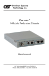
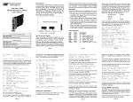
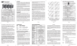
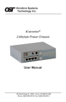
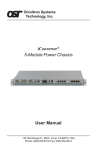
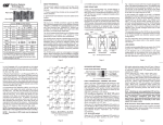
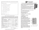
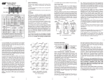
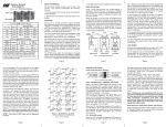
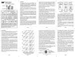
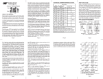
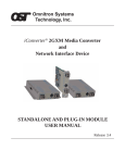
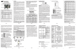
T3/E3 MODEL NUMBER REFERENCE CHART:
FRONT PANEL DIP-SWITCH SETTINGS:
The following DIP-switches are located on the front of the T3/E3 converter.
These switches provide data path control (normal operation and loopbacks) and test patterns (all 1’s) that assist in installation and fault isolation.
iConverter T3/E3 Coax Dual Fiber Modules
iConverter® T3/E3 User Manual
Connector Type
Fiber Type
Distance
ST
SC
MT-RJ
LC
SFP
-
-
-
-
-
-
8759-0*
MM
5 km
8740-0
8742-0
8744-0
-
-
SM
30 km
8741-1
8743-1
8745-1
8747-1
-
SM
60 km
8741-2
8743-2
-
8747-2
-
SM
120 km
-
8743-3
-
8747-3
-
iConverter T3/E3 Coax Single-Fiber Modules
Fiber /
Connector
Type
Tx: 1310 nm,
Rx: 1550 nm
Distance
Tx: 1550 nm,
Rx: 1310 nm
OVERVIEW:
SM / SC
20 km
8750-1
8751-1
The iConverter T3/E3 managed media converter is a member of the
modular iConverter product family. The T3/E3 provides standard T3
(B3ZS line protocol, 44.763Mbps) or E3 (HDB3 line protocol, 34.368Mbps)
coax to fiber conversion and can be used by telco service providers
and enterprise users to connect devices such as PBXs, multiplexers,
routers and video servers via multimode (MM), single-mode (SM) or
single-mode single-fiber (SF) fiber.
SM / SC
40 km
8750-2
8751-2
Fig. 1 Front Panel DIP-Switches
Normal Mode Operation (Straight Through):
The default DIP-switch setting (all dip-switches to the left) sets the converter
to its Normal Mode and allows data to flow straight through between the
BNC and Fiber ports (Figure 2).
For wide temperature (-40 to 60º C), add a "W" to the end of the model number.
Consult factory for extended temperature (-40 to 75º C) models.
When using single-fiber (SF) media converter models, the TX wavelength on one end
has to match the RX wavelength on the other.
*See SFP data sheet under Fast Ethernet for supported transceiver models.
Fig. 2 Normal Mode and DIP-Switch Settings
“FLB” Dip-Switch - Local Fiber Mode Operation (Fiber Loopback):
This DIP-switch facilitates the testing of the fiber cables. When the “FLB”
dip-switch is in the right position, it sets the fiber port to a Local Fiber
Loopback Mode (Figure 3) and the “FLB” LED is turned ON. When in this
mode, data received at the Fiber-In is forwarded to the BNC-out and the
Fiber-Out. If no data is received at Fiber-In, an AIS pattern is transmitted
out both BNC-Out and Fiber-Out. By returning the DIP-switch to the left
position, the unit resumes normal operation.
Designed to extend the standard T3/E3 Coax network distances over
fiber, this converter provides protection from environmental noise and
effectively increases high-speed network reliability.
The T3/E3 module can be used in any of the iConverter chassis such
as the 1-Module, 2-Module, 5-Module and 19-Module chassis.
The T3/E3 can be used in a managed or unmanaged fashion. When
unmanaged, it can be installed in an iConverter chassis without a
Network Management Module (NMM). To be managed, a NMM module
must be installed in the same chassis as the T3/E3 module. To read
about specific management functionality, refer to the NetOutlook ™
user manual T3/E3 section.
“CLB” DIP-Switch - Local Coax Mode Operation (Coax Loopback):
This DIP-switch facilitates the testing of the coax cables. When the “CLB”
dip-switch is in the right position, it sets the coax port to a Local Coax
Loopback Mode (Figure 4) and the “CLB” LED is turned ON. When in this
mode, data received at the BNC-In is forwarded to the BNC-Out and the
Fiber-Out. If no data is received at BNC-In, an AIS pattern is transmitted
out both BNC-Out and Fiber-Out. By returning the DIP-switch to the left
position, the unit resumes normal operation.
ON BOARD DIP-SWITCH SETTINGS:
Remote Loopback Mode:
When both the “FLB” and “CLB” DIP-switches are in the right position, they
force a remote unit to loop back its fiber and coax ports (Figure 5). This
facilitates test of the fiber cables and the remote unit without having to
physically set DIP-switches on the remote unit. While in this mode, the
local unit’s BNC is set to a local loopback, and its “FLB” and “CLB” LEDs
are turned ON.
While in the Remote Loopback Mode, the local unit sends a test pattern to
the remote unit. This pattern forces the remote unit into the loopback mode
and is also returned back to the local unit. When forced into the Remote
Loopback Mode, the remote unit’s “FLB” and “CLB” blink slowly (1Hz).
When the test pattern is received successfully at the local unit’s Fiber-In,
the “TST” LED blinks rapidly (10Hz). Any other data causes slow “TST”
blinking (1Hz). If no data is returned to Fiber-In, the LED is turned OFF.
Returning both dip-switches to the left position, causes the local and
remote units to resume normal operation.
T3/E3 LED REFERENCE CHART:
Function
"Legend"
Color
OFF
State
“PRBS” Pseudo Random Pattern Generator Control DIP-Switch:
When in the right position, the converter forces Pseudo Random pattern
out of the Coax-Out port. The data received at Fiber-In is discarded and
the data at Coax-In is passed through to Fiber-Out.
T3/E3 SPECIFICATION CHART:
ON / Blinking state
Power
"Pwr"
Amber No Power On: Power available
Fiber Activity
"Act"
No valid
Green
data
Fiber AIS
"AIS"
Amber
--
Fiber
Loopback
"FLB"
Coax
Loopback
"CLB"
Fast blink (10Hz): Data Received
Fast blink (10Hz): AIS Received.
No Test
Amber Data
Received
Local unit asserting Remote Loopback:
Fast blink (10Hz): Test pattern received.
Slow blink (1 Hz): Unexpected pattern
received.
Special Case:
Three quick blinks (2Hz) and pause (1sec.):
Illegal dip-switch selection.
Amber Normal
ON: Local Fiber Loopback.
If "CLB" also "ON" indicates that the unit is
the Local Unit in Remote Loopback Mode.
Slow blink (1Hz) and also "CLB" in slow
blink: indicates that the unit is the Remote
Unit in Remote Loopback Mode.
Amber Normal
ON: Local Coax Loopback.
If "FLB" also "ON" indicates that the unit is
the Local Unit in Remote Loopback Mode.
Slow blink (1Hz) and also "FLB" in slow
blink: indicates that the unit is the Remote
Unit in Remote Loopback Mode.
No valid
data
T3/E3
Model Type
Protocols
Fig. 6 Board Mounted DIP-Switches
“CEN/CDIS” and “FEN/FDIS” Port Control DIP-Switches:
When both DIP-switches are in the left position, the ports are enabled.
When the “CEN/CDIS” is in the right position, the coax port is disabled.
When the “FEN/FDIS” is in the right position, the fiber port is disabled.
Fig. 3 Fiber Loopback and DIP-Switch Settings
Page 3
Page 2
Fiber Test
detected
"TST"
“<225/>225” Coax Build-Out Distance selection:
When this DIP-switch is in the left position, a distance of less than 225 ft.
is selected. When in the right position, a distance of 225 ft. or higher is
selected. Select the appropriate distance for your application.
Copper Connectors
Fiber Connectors
Controls
LED Displays
Dimensions
ANSI: T1.102, T1.107,
T1.404, T1-404a (T3),
ITU: G.703, (E3), G.751, O.151
ETSI: EN 300 689, 300 686, 300 687
RG-59 Coax, 75 ohm, BNC
DS3: 380m, E3: 440m
SC, ST, LC, MT-RJ, SFP
T3/E3 Sel, Coax Build-Out, Coax En/Dis,
Fiber En/Dis, AIS to Fiber, AIS to Coax,
PRBS to Coax, Loop-Bk Coax,
Loop-Bk Fiber, Loop-Bk Remote
Power, Fiber Act, Coax Act, Fiber AIS Det,
Coax AIS Det, Coax PRBS Det,
Fiber Test, Fiber Loop-Bk, Coax Loop-Bk
W:0.85" x D:4.5" x H:2.8"
Weight
Compliance
Left
Position
Left Function
Right
Position
Right Function
[1]
T3 Select
OFF
(default)
-
T3
T3 Selected
[2]
E3 Select
OFF
(default)
E3 is selected
when T3 and
STS-1 are OFF
E3
E3 Selected
[3]
STS-1 Select
OFF
(default)
-
STS-1
STS-1 Selected
[4]
Coax build-out
distance selection
<225
(default)
Short distance,
less than 225ft.
>225
Long distance,
equal-to or
more than 225ft
[5]
Coax port control
CEN
(default)
Coax port
enabled
CDIS
Coax port
disabled [OFF]
[6]
Fiber port control
FEN
(default)
Fiber port
enabled
FDIS
Fiber port
disabled [OFF]
[7]
Force PRBS to
BNC-Out
OFF
(default)
Normal data
PRBS
Force PRBS[1]
to BNC-Out
8 = Reserved
-
-
-
-
Power Requirement
0.7A @ 3.3VDC (typical)
Fast blink (10Hz): Data Received
Temperature
Standard:
Wide:
Storage:
0 to 50º C
-40 to 60º C
-40 to 80º C
Coax Activity
"ACT"
Green
Coax AIS
detected
"AIS"
Amber
--
Fast blink (10Hz): AIS Received.
Humidity
5 to 95% (non-condensing)
Coax PRBS
detected
"PRBS"
Altitude
-100m to 4000m
Amber
--
Blink 10 Hz: PRBS Received.
Blink 1 Hz: Forcing PRBS onto BNC-Out.
MTBF (hrs)
Page 7
Fig. 5 Remote Loopback and DIP-Switch Settings
Page 4
MOUNTING INSTRUCTIONS and CABLE ATTACHMENTS:
iConverter modules are hot-swappable and can be installed into any
chassis in the iConverter family.
1. Carefully slide the iConverter module into the installation slot, aligning
the module with the installation guides. Ensure that module is firmly
seated against the backplane.
2. Secure the module by securing the panel fastener screw (attached to
module) to chassis front.
3. When using an SFP model (8759-0), insert the SFP Fiber transceiver
into the SFP receptacle on the module.
Note: The release latch of the SFP Fiber transceiver must be in
the closed position before insertion.
4. Connect the fiber cables between the T3/E3 converters. The Transmit
(TX) must attach to the Receive (RX) and the Receive must attach
to the Transmit.
5. When using a single-fiber models, you must use mating converters.
For example, if one converter is the model 8750-1 (TX=1310nm,
RX= 1550nm), the other converter must be model 8751-1 (TX=1550nm,
RX=1310nm).
6. Attach the BNC cables to the T3/E3 converter and attach the other
end of the cables to appropriate network equipment. The Transmit must
attach to the Receive and the Receive must attach to the Transmit.
Page 5
For warranty service, the product must be sent to an Omnitron designated facility, at Buyer’s expense. Omnitron will pay the shipping charge
to return the product to Buyer’s designated US address using Omnitron’s
standard shipping method.
Limitation of Warranty
The foregoing warranty shall not apply to defects resulting from improper
or inadequate use and/or maintenance of the equipment by Buyer, Buyersupplied equipment, Buyer-supplied interfacing, unauthorized modifications or tampering with equipment (including removal of equipment cover
by personnel not specifically authorized and certified by Omnitron), or misuse, or operating outside the environmental specification of the product
(including but not limited to voltage, ambient temperature, radiation, unusual dust, etc.), or improper site preparation or maintenance. No other
warranty is expressed or implied. Omnitron specifically disclaims the implied warranties of merchantability and fitness for any particular purpose.
Exclusive Remedies
The remedies provided herein are the Buyer’s sole and exclusive
remedies. Omnitron shall not be liable for any direct, indirect, special,
incidental, or consequential damages, whether based on contract, tort, or
any legal theory.
8 oz.
UL, CE, FCC Class A
510,000
Note: Some combinations of DIP-switch settings are illegal, and
will be indicated by the Fiber Test “TST” LED blinking quickly three
times followed by a pause.
Page 6
[Switch
Position]
Function
Note: [1] Pseudo Random Bit Sequence [PRBS] is a data pattern
defined by ITU O.151 spec: E3: 2^23-1, T3: 2^15-1
Page 1
“T3” “E3” and “STS-1” DIP-Switches - Select Protocol:
When the “T3” DIP-switch is in the right position, the T3 protocol is
selected. When the “E3” DIP-switch is in the right position, the E3 protocol
is selected. When the “STS-1” DIP-switch is in the right position, the STS-1
protocol is selected. Only one of the three DIP-switches may be in the
right position at any one time. The default setting of the module has no
mode selected (the module will default to E3 mode with no switches set).
“CAIS” Force AIS to Coax (Force 1’s to Coax):
When the “CAIS” dip-switch is in the right position, an “all
ones” pattern is forced out the BNC-Out port. The Fiber-In
data is discarded and BNC-In data is passed through to
Fiber-Out. By returning the dip-switch to the left position,
the unit resumes normal operation.
Fig. 4 Coax Loopback and DIP-Switch Settings
This User Manual covers the models listed in the following table.
The On Board DIP-switches facilitate the selection between T3, E3,
STS-1 protocols, the coax distance, fiber and coax port control and the
injection of pseudo random data patterns into the coax.
“FAIS” Force AIS to Fiber (Force 1’s to Fiber):
When the “FAIS” dip-switch is in the right position, an “all
ones” pattern is forced out the Fiber-Out port. The Coax-In
data is discarded and Fiber-In data is passed through to
BNC-Out. By returning the dip-switch to the left position,
the unit resumes normal operation.
Page 8
Warning
The operating description in this Instruction Manual is for use by qualified
personnel only. To avoid electrical shock, do not perform any servicing of
this unit other than that contained in the operating instructions, unless you
are qualified and certified to do so by Omnitron Systems Technology, Inc.
Warranty
This product is warranted to the original purchaser against defects in
material and workmanship for a period of TWO YEARS from the date of
shipment. A LIFETIME warranty may be obtained by the original purchaser by
REGISTERING this product with Omnitron within 90 days from the date of
shipment. TO REGISTER, COMPLETE AND MAIL OR FAX THE ENCLOSED
REGISTRATION FORM. Or you may register your product on the Internet
at www.omnitron-systems.com. During the warranty period, Omnitron will,
at its option, repair or replace a product which is proven to be defective.
Page 9
TECHNICAL SUPPORT:
For help with this product, contact our Technical Support:
Phone:
(949) 250-6510
Fax:
(949) 250-6514
Address: Omnitron Systems Technology, Inc.
140 Technology Dr., #500
Irvine, CA 92618 USA
E-mail:
[email protected]
URL:
www.omnitron-systems.com
Form: 040-08740-001D 2/08
Page 10