1
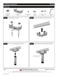
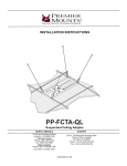
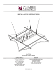
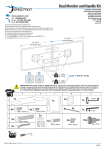
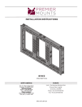
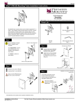
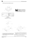
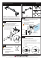
MM-CB2
Installation Instructions
Introduction
Parts List
M4 x 10mm Combo Screws
(Qty 8)
4” Cable Ties (Qty 2)
The MM-CB2 is a dual multimonitor mount arm that works with any
2” tubing. Each mounting head provides 90° of omnidirectional tilt.
The mounting heads include both 75x75mm and 100x100mm VESA
mounting patterns. The arm includes integrated cable management
tabs to keep wires and cables protected and organized. The mounting
heads can be horizontally adjusted.
Step 1
1.
Slide your mounting arm over the pole and base (Figure 1)
(not included, but should be previously installed).
MM-CB2
Dual Multi-Monitor Mounting Arm
(Qty 1)
5/32” Allen Key
(Qty 1)
Step 3
1)
Insert the heads of the M4 screws through the keyhole slots on the
mounting head (Figure 5).
2)
Insert the remaining two (2) M4x10mm screws, into the bottom mounting
points (Figure 4)
3)
Repeat sub-steps 1 & 2 for the second display.
4)
Tighten all M4 screws.
Do not overtighten the mounting hardware
Determine the position on the pole desired for your mounting arm.
2.
Socket Wrench
(Qty 1)
Figure 4
Once in desired position,tighten the two (2)
pre-intalled M8 x 6mm set screws in the
holes in the back of the MM-CB2. Tighten
with included allen key (Figure 2).
MM-CB2 Mount
(Figure 1)
Thread Insert in Flat
Panel or Adapter Plate
Figure 5
Keyhole Slot
M4 Screw Partially
Threaded Into Flat Panel
Step 4
To adjust the position of your displays horizontally
(Figure 2)
Step 2
B
Are you installing to a 75x75mm or
100x100mm VESA moutning pattern?
For 75x75mm, use mounting points A. For
100x100mm use points B in figure 3.
1)
Thread the M4 screws to one-half of their
length into the top two mounting holes on
each display, but do not tighten the M4
screws at this time.
B
B
A
A
A
A
(Figure 3)
Turn the mounting head adjustment knob counter clockwise until the
mounting head is lose enough to slide easily along the pole.
2.
Slide the display (or mounting head) to the desired position.
3.
When in place, turn the adjustment head clockwise to tighten it. Make sure
it is completely secure and does not move before you move on to the next
display or finish.
4.
Repeat steps for other displays if desired.
Loosen
& Adjust
Tighten
& Secure
B
Page 1
9531-000-041-00
1.
Installation Instructions
3100 E. Miraloma Avenue, Anaheim, CA 92806 | 800.368.9700 USA | F 800.832.4888 | www.mounts.com
Unit 3, The Moorings Business Park, Channel Way | Longford, Conventry, CV6 6RH, UK | +44 (0) 2476 644105 | F +44 (0) 2476 644165
Installation Instructions
PREMIER MOUNTS
Step 4
To adjust the tension and/or tilt angle of the mounting head:
1)
Adjust the mounting head by utilizing the 90° continuous tilt, until it is in the
desired position.
2)
Remove the side and bottom cosmetic cap from the mounting
head (Figure 6)
3)
Use the supplied socket wrench to tighten both nuts.
4)
The side nut secures the tilt position (Point A), while the bottom nut secures
the pivot (Point B).
Do not overtighten the mounting hardware
LIMITED LIFETIME WARRANTY
What and Who is Covered by this Limited Warranty and for How Long
Premier Mounts warrants this product to be free from defects in material and workmanship for the lifetime of the
original owner of this product. The limited warranty is valid only for the original purchaser of the product.
What Premier Mounts Will Do
At the sole option of Premier Mounts, Premier Mounts will repair or replace any product or product part that is
defective. If Premier Mounts chooses to replace a defective product or part, a replacement product or part will be
shipped to you at no charge, but you must pay any labor costs.
What is Not Covered; Limitations
PREMIER MOUNTS DISCLAIMS ANY LIABILITY FOR DAMAGE TO MOUNTS, ADAPTERS, DISPLAYS,
PROJECTORS, OTHER PROPERTY, OR PERSONAL INJURY RESULTING, IN WHOLE OR IN PART, FROM
IMPROPER INSTALLATION, MODIFICATION, USE OR MISUSE OF ITS PRODUCTS.
PREMIER MOUNTS DISCLAIMS ALL OTHER WARRANTIES, EXPRESS OR IMPLIED, INCLUDING
WARRANTIES OF MERCHANTABILITY AND FITNESS FOR A PARTICULAR PURPOSE. PREMIER MOUNTS
IS NOT RESPONSIBLE FOR INCIDENTAL OR CONSEQUENTIAL DAMAGES, INCLUDING BUT NOT LIMITED
TO, INABILITY TO USE ITS PRODUCTS OR LABOR COSTS FOR REMOVING AND REPLACING DEFECTIVE
PRODUCTS OR PARTS. SOME STATES DO NOT ALLOW THE EXCLUSION OR LIMITATION OF INCIDENTAL
OR
CONSEQUENTIAL DAMAGES, SO THE ABOVE LIMITATION OR EXCLUSION MAY NOT APPLY TO YOU.
What Customers Must Do for Limited Warranty Service
If you discover a problem that you think may be covered by the warranty you MUST REPORT it in writing to the
address below within thirty (30) days. Proof of purchase (an original sales receipt) from the original consumer
purchaser must accompany all warranty claims. Warranty claims must also include a description of the problem,
the purchaser’s name, address, and telephone number. General inquiries can be addressed to Premier Mounts
A
Customer Service at 1-800-368-9700. Warranty claims will not be accepted over the phone or by fax.
B
(Figure 6)
Premier Mounts
Attn: Warranty Claim
3130 East Miraloma Ave.
Anaheim, CA 92806
How State Law Applies
THIS WARRANTY GIVES YOU SPECIFIC LEGAL RIGHTS, AND YOU MAY ALSO HAVE OTHER RIGHTS
WHICH VARY FROM STATE TO STATE.
Bottom View
Page 2
Installation Instructions
3100 E. Miraloma Avenue, Anaheim, CA 92806 | 800.368.9700 USA | F 800.832.4888 | www.mounts.com
Unit 3, The Moorings Business Park, Channel Way | Longford, Conventry, CV6 6RH, UK | +44 (0) 2476 644105 | F +44 (0) 2476 644165