1
Zlinx Radio Modem
ZP Series
Documentation Number: ZP9D-115RM-LR-0812
pn#7697R4
This product designed and manufactured in Ottawa, Illinois USA
of domestic and imported parts by
707 Dayton Road -- P.O. Box 1040 -- Ottawa, IL 61350 USA
Phone (815) 433-5100 -- General Fax (815) 433-5105
Phone (815) 433-5100 -- General Fax (815) 433-5105
Website: www.bb-elec.com
European Headquarters
B&B Electronics
Westlink Commercial Park -- Oranmore, Co. Galway, Ireland
Phone +353 91-792444 -- Fax +353 91-792445
Website: www.bb-europe.com
B&B Electronics Mfg. Co. Inc. -- June 2008
Manual Documentation Number: ZP9D-115RM-LR-0812
1
B&B Electronics Mfg Co Inc – 707 Dayton Rd - PO Box 1040 - Ottawa IL 61350 - Ph 815-433-5100 - Fax 815-433-5104 – www.bb-elec.com
B&B Electronics – Westlink Commercial Park – Oranmore, Galway, Ireland – Ph +353 91-792444 – Fax +353 91-792445 – www.bb-europe.com
This document contains information that is proprietary and confidential to B&B
Electronics Mfg. Co. Inc. The methods described herein are for the exclusive use of
B&B Electronics authorized personnel. Any unauthorized use or dissemination of the
information contained in the document is strictly forbidden.
2
Manual Documentation Number: ZP9D-115RM-LR-0812
B&B Electronics Mfg Co Inc – 707 Dayton Rd - PO Box 1040 - Ottawa IL 61350 - Ph 815-433-5100 - Fax 815-433-5104 – www.bb-elec.com
B&B Electronics – Westlink Commercial Park – Oranmore, Galway, Ireland – Ph +353 91-792444 – Fax +353 91-792445 – www.bb-europe.com
Table of Contents
Introduction
PACKAGE CONTENTS
4
4
Hardware Installation
DIP SWITCH SETTINGS
MOUNTING AND POWER
SERIAL CONNECTIONS
RS-232
RS-422/485
WIRELESS LINK FAILURE OUTPUT
RADIO FREQUENCY INFORMATION
Zlinx Manager Software
INSTALLATION
SET UP
ON-LINE CONFIGURATION
TEST / TROUBLESHOOT
FIRMWARE UPDATE
5
5
5
6
6
7
8
8
10
10
10
12
16
18
Specifications
19
Special Consideration for Class 1 DIV 2
21
Advanced Programming
22
AT COMMANDS
22
BINARY COMMANDS
23
COMMAND REFERENCE TABLE
24
ZLINX COMMANDS (ZLINX RADIO MODEMS EXPECT NUMERICAL VALUES
IN HEXADECIMAL. HEXADECIMAL VALUES ARE DESIGNATED BY A “0X”
PREFIX. DECIMAL EQUIVALENTS ARE DESIGNATED BY A “D” SUFFIX.) 24
COMMAND DESCRIPTIONS
28
Manual Documentation Number: ZP9D-115RM-LR-0812
3
B&B Electronics Mfg Co Inc – 707 Dayton Rd - PO Box 1040 - Ottawa IL 61350 - Ph 815-433-5100 - Fax 815-433-5104 – www.bb-elec.com
B&B Electronics – Westlink Commercial Park – Oranmore, Galway, Ireland – Ph +353 91-792444 – Fax +353 91-792445 – www.bb-europe.com
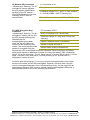
Introduction
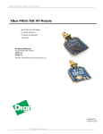
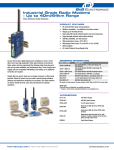
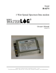
Easy to install, up to 14 mile range No wires, no
cables! Zlinx radio modems get your
data moving farther, easier, and at less cost than
running cable. Plug-n-play, Modbus compatible,
signal strength indicator, space saving DIN rail
mounting. Heavy-duty, wide temperature design
handles most industrial power configurations and
tough indoor/outdoor environments.
Model #
ZP9D-115RM-LR
Frequency
900MHz
Radio
Power
Configurable
1 mW to 1W
RF Data Rate
Configurable 9600
bps or 115Kbps
Package Contents
Radio Modem
Antenna
Software CD
Manual on CD
Will require separate 18-30VAC or 10-48VDC Power Supply
ZP9D-115RM-LR = 5.0W max
4
Manual Documentation Number: ZP9D-115RM-LR-0812
B&B Electronics Mfg Co Inc – 707 Dayton Rd - PO Box 1040 - Ottawa IL 61350 - Ph 815-433-5100 - Fax 815-433-5104 – www.bb-elec.com
B&B Electronics – Westlink Commercial Park – Oranmore, Galway, Ireland – Ph +353 91-792444 – Fax +353 91-792445 – www.bb-europe.com
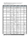
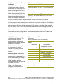
Hardware Installation
Dip Switch Settings
Dipswitch
1
2
3
4
OFF
4-wire
4-wire
No termination
RS-422
ON
2-wire
2-wire
Termination
RS-485
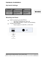
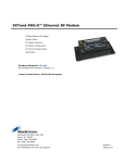
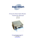
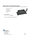
Mounting and Power
Install on properly grounded DIN rail
o Operating Temperature is -40 to 85
o Operating Humidity is 10-90% non-condensing
Connect Power Supply
o Power supply is 10-48 VDC or 18-30 VAC
10-48 VDC
or
18-30 VAC
Manual Documentation Number: ZP9D-115RM-LR-0812
5
B&B Electronics Mfg Co Inc – 707 Dayton Rd - PO Box 1040 - Ottawa IL 61350 - Ph 815-433-5100 - Fax 815-433-5104 – www.bb-elec.com
B&B Electronics – Westlink Commercial Park – Oranmore, Galway, Ireland – Ph +353 91-792444 – Fax +353 91-792445 – www.bb-europe.com
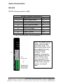
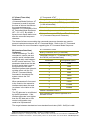
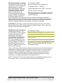
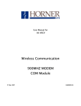
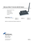
Serial Connections
RS-232
RS-232 Always present on DB9
Wiring Terminal Identification
DB9F Pin
Signal Name
Direction
1
Data Carrier Detect*
--2
Receive Data
Out
3
Transmit Data
In
4
Data Terminal Ready
In
5
Signal Ground
--6
Data Set Ready*
--7
Request To Send
In
8
Clear To Send
Out
9
Not used
--* - Pins 1 & 6 are not used. They are tied together
Note: The DTR input is
used to put the radio
into sleep mode. The
radio sleep option must
be enabled first using
the configuration
software. Once
enabled, lowering the
DTR signal will put the
radio in sleep mode
and raising the DTR
signal will put the radio
in idle mode, ready to
receive or transmit
data.
6
Manual Documentation Number: ZP9D-115RM-LR-0812
B&B Electronics Mfg Co Inc – 707 Dayton Rd - PO Box 1040 - Ottawa IL 61350 - Ph 815-433-5100 - Fax 815-433-5104 – www.bb-elec.com
B&B Electronics – Westlink Commercial Park – Oranmore, Galway, Ireland – Ph +353 91-792444 – Fax +353 91-792445 – www.bb-europe.com
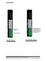
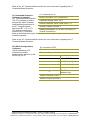
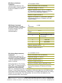
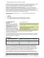
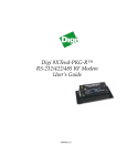
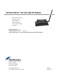
RS-422/485
RS-485 (2Wire)
RS-422/485 (4Wire)
Manual Documentation Number: ZP9D-115RM-LR-0812
7
B&B Electronics Mfg Co Inc – 707 Dayton Rd - PO Box 1040 - Ottawa IL 61350 - Ph 815-433-5100 - Fax 815-433-5104 – www.bb-elec.com
B&B Electronics – Westlink Commercial Park – Oranmore, Galway, Ireland – Ph +353 91-792444 – Fax +353 91-792445 – www.bb-europe.com
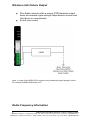
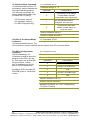
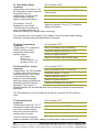
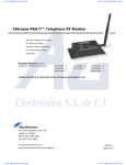
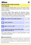
Wireless Link Failure Output
Zlinx Radio modems offer a source (PNP)transistor output
when the wireless signal strength drops below a critical level
(link failure or miss packets)
40 mA max current
Note: In order for the RSSI LED to continuously indicate the signal strength, set the
RP command (RSSI PWM timer) to FF.
Radio Frequency Information
8
Manual Documentation Number: ZP9D-115RM-LR-0812
B&B Electronics Mfg Co Inc – 707 Dayton Rd - PO Box 1040 - Ottawa IL 61350 - Ph 815-433-5100 - Fax 815-433-5104 – www.bb-elec.com
B&B Electronics – Westlink Commercial Park – Oranmore, Galway, Ireland – Ph +353 91-792444 – Fax +353 91-792445 – www.bb-europe.com
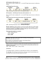
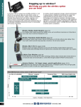
The ZP9D-115RM-LR has an indoor range of up to 3000
feet and an outdoor range of up to 14 miles.
These ranges are for line of sight installations using the
supplied antenna. Performance may vary depending on your
particular installation.
The antenna connection on the radio modem is an RPSMA
female plug.
B&B Electronics has a wide variety of accessory antennas.
Visit www.bb-elec.com for more information.
Model #
ZP9D-115RM-LR
Frequency
900MHz
Radio
Power
1mW to 1W
(selectable)
Manual Documentation Number: ZP9D-115RM-LR-0812
RF Data
Rate
9600 bps
to 115Kbps
9
B&B Electronics Mfg Co Inc – 707 Dayton Rd - PO Box 1040 - Ottawa IL 61350 - Ph 815-433-5100 - Fax 815-433-5104 – www.bb-elec.com
B&B Electronics – Westlink Commercial Park – Oranmore, Galway, Ireland – Ph +353 91-792444 – Fax +353 91-792445 – www.bb-europe.com
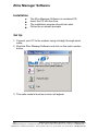
Zlinx Manager Software
Installation
The Zlinx Manager Software is contained CD.
Insert the CD into the drive.
The installation program should auto start.
Follow the on screen prompts.
Set Up
1. Connect your PC to the modem using a straight through serial
cable.
2. Start the Zlinx Manage Software and click on the radio modem
button.
3. The radio modem launcher screen will appear
10
Manual Documentation Number: ZP9D-115RM-LR-0812
B&B Electronics Mfg Co Inc – 707 Dayton Rd - PO Box 1040 - Ottawa IL 61350 - Ph 815-433-5100 - Fax 815-433-5104 – www.bb-elec.com
B&B Electronics – Westlink Commercial Park – Oranmore, Galway, Ireland – Ph +353 91-792444 – Fax +353 91-792445 – www.bb-europe.com
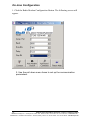
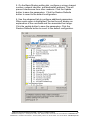
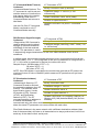
3. Click on the Radio Modem Configuration button to configure the
modem on-line or the Radio Modem Configuration Button (offline) to
configure the modem offline. Follow the on screen directions to
configure the modem. Note: using the off-line configuration button
skips the auto modem discovery process.
Manual Documentation Number: ZP9D-115RM-LR-0812
11
B&B Electronics Mfg Co Inc – 707 Dayton Rd - PO Box 1040 - Ottawa IL 61350 - Ph 815-433-5100 - Fax 815-433-5104 – www.bb-elec.com
B&B Electronics – Westlink Commercial Park – Oranmore, Galway, Ireland – Ph +353 91-792444 – Fax +353 91-792445 – www.bb-europe.com
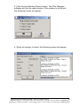
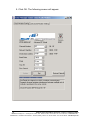
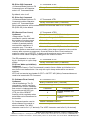
On-Line Configuration
1. Click the Radio Modem Configuration Button. The following screen will
appear.
2. Use the pull down menu items to set up the communication
parameters.
12
Manual Documentation Number: ZP9D-115RM-LR-0812
B&B Electronics Mfg Co Inc – 707 Dayton Rd - PO Box 1040 - Ottawa IL 61350 - Ph 815-433-5100 - Fax 815-433-5104 – www.bb-elec.com
B&B Electronics – Westlink Commercial Park – Oranmore, Galway, Ireland – Ph +353 91-792444 – Fax +353 91-792445 – www.bb-europe.com
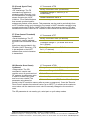
3. Click the Auto Modem Search button. The Zlinx Manager
software will find the radio modem. If the modem is not found,
the following screen will appear.
4. When the modem is found, the following screen will appear.
Manual Documentation Number: ZP9D-115RM-LR-0812
13
B&B Electronics Mfg Co Inc – 707 Dayton Rd - PO Box 1040 - Ottawa IL 61350 - Ph 815-433-5100 - Fax 815-433-5104 – www.bb-elec.com
B&B Electronics – Westlink Commercial Park – Oranmore, Galway, Ireland – Ph +353 91-792444 – Fax +353 91-792445 – www.bb-europe.com
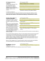
5. Click OK. The following screen will appear.
14
Manual Documentation Number: ZP9D-115RM-LR-0812
B&B Electronics Mfg Co Inc – 707 Dayton Rd - PO Box 1040 - Ottawa IL 61350 - Ph 815-433-5100 - Fax 815-433-5104 – www.bb-elec.com
B&B Electronics – Westlink Commercial Park – Oranmore, Galway, Ireland – Ph +353 91-792444 – Fax +353 91-792445 – www.bb-europe.com
5. On the Basic Modem setting tab, configure a unique channel
number, network identifier, and destination address. This will
prevent interference from other modems. Click the Update
button to save the parameters. Click the Restore Defaults
button to revert to the default configuration.
6. Use the advanced tab to configure additional parameters.
When each option is highlighted, the text box will display an
explanation of the command and the associated hex range.
Click the update button to save the parameters. Click the
Restore Defaults button to revert to the default configuration.
Manual Documentation Number: ZP9D-115RM-LR-0812
15
B&B Electronics Mfg Co Inc – 707 Dayton Rd - PO Box 1040 - Ottawa IL 61350 - Ph 815-433-5100 - Fax 815-433-5104 – www.bb-elec.com
B&B Electronics – Westlink Commercial Park – Oranmore, Galway, Ireland – Ph +353 91-792444 – Fax +353 91-792445 – www.bb-europe.com
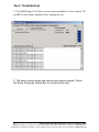
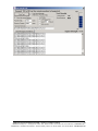
Test / Troubleshoot
1. The RSSI Range Test allows you test your installation. Cross connect TD
and RD on the remote modem before running the test.
2. The basic screen shows test results and signal strength. Check
the Show Advanced Option Box to customize the test.
16
Manual Documentation Number: ZP9D-115RM-LR-0812
B&B Electronics Mfg Co Inc – 707 Dayton Rd - PO Box 1040 - Ottawa IL 61350 - Ph 815-433-5100 - Fax 815-433-5104 – www.bb-elec.com
B&B Electronics – Westlink Commercial Park – Oranmore, Galway, Ireland – Ph +353 91-792444 – Fax +353 91-792445 – www.bb-europe.com
Manual Documentation Number: ZP9D-115RM-LR-0812
17
B&B Electronics Mfg Co Inc – 707 Dayton Rd - PO Box 1040 - Ottawa IL 61350 - Ph 815-433-5100 - Fax 815-433-5104 – www.bb-elec.com
B&B Electronics – Westlink Commercial Park – Oranmore, Galway, Ireland – Ph +353 91-792444 – Fax +353 91-792445 – www.bb-europe.com
Firmware Update
1. Connect your PC to the radio modem using a straight through serial cable
and the auto connect function. The new firmware must be stored on the
PC’s local drive.
2. From the Zlinx Manager Radio Modem launch screen, click the firmware
update button.
3. Once connected, the software will determine which firmware versions
are available on the PC and what version is loaded in the modem. The
following screen allows you to chose which firmware version to load.
4. Select the firmware version to load from the pull down menu and
click the update button.
18
Manual Documentation Number: ZP9D-115RM-LR-0812
B&B Electronics Mfg Co Inc – 707 Dayton Rd - PO Box 1040 - Ottawa IL 61350 - Ph 815-433-5100 - Fax 815-433-5104 – www.bb-elec.com
B&B Electronics – Westlink Commercial Park – Oranmore, Galway, Ireland – Ph +353 91-792444 – Fax +353 91-792445 – www.bb-europe.com
Specifications
RF Properties
Physical Standard
Range
Frequency
Transmit Power
Software
Support
Features
Proprietary radio
up to 3000 feet indoor or 14 miles outdoor
900MHz
1W (selectable)
Zlinx Radio Modem
Windows 2000, 2003 Server, XP, and Vista
AT Command
Terminal emulation
RSSI signal range test
Modem emulation
Antenna Options
External Reverse Polarity SMA male jack connector, omni
directional (included with product)
Radio Address
Defaulted at factory, set by software otherwise
Serial settings
Baud
Data bit
Parity
Stop bit
1200, 2400, 4800, 9600, 19200, 38400, 57600, 115200,
230400
7, 8
None, even, odd, mark, space
1, 2
RS-232
Connector
Lines
Connector
Lines
DB9F DCE
TX, RX, RTS, CTS, DTR, RI, GND
Removable terminal block
TX, RX, GND
Connector
Lines
Removable terminal block
2 or 4 wire – TX+, TX-, RX+, RX-, GND (2 or 4 wire
dipswitch selectable)
120 Ohm Dipswitch selectable
RS-422
Termination
RS-485
Connector
Lines
SD control
Termination
Removable terminal block
2 or 4 wire with SD control – TX+, TX-, RX+, RX-, GND (2 or
4 wire dipswitch selectable)
Bit wise
120 Ohm Dipswitch selectable
Transistor link failure
Connector
Output type
No wireless signal or RSSI LED off
Removable terminal block with RS-422/485
Open collector, dry contact, 40mA
Power Supply
Connector
Input Voltage
Removable terminal block
10–48VDC, 18-30VAC
Manual Documentation Number: ZP9D-115RM-LR-0812
19
B&B Electronics Mfg Co Inc – 707 Dayton Rd - PO Box 1040 - Ottawa IL 61350 - Ph 815-433-5100 - Fax 815-433-5104 – www.bb-elec.com
B&B Electronics – Westlink Commercial Park – Oranmore, Galway, Ireland – Ph +353 91-792444 – Fax +353 91-792445 – www.bb-europe.com
Power Consumption
5.0W max
Dimensions
1.2W x 3.3D x 4.7H
Environmental
Operating
Temperature
Storage Temperature
Operating Humidity
Intended for indoor use only
-40 to 85ºC (-40 to 185ºF)
Enclosure Rating
Rating
Mounting
LED Status
-40 to 85ºC (-40 to 185ºF)
10 to 90% non-condensing
IP30
DIN rail mount, 35mm
Front Panel LED
Power
RSSI (Signal Strength)
Wireless Data
Wiring
Size / Type
Temperature Rating
Terminal Torque
Certifications
FCC
CE
UL
RoHS directive (lead
free)
20
Status
Red = On
OFF = No Power
Green = Strong
Yellow = OK
Red = Weak
OFF = No Signal
Green = Blink on with data
Note: In order for the RSSI LED to continuously indicate the
signal strength, set the RP command (RSSI PWM Timer) to
FF.
(Copper Wire Only)
28 to16 AWG / SOLID COPPER
105 °C (221 °F) Minimum
0.2 Nm (Newton-meters)
FCC Part 15 Class B
CISPR (EN55022) Class B
EN61000-6-1 Generic Standards for Residential,
Commercial, & Light Industrial
EN61000-4-2 ESD
EN61000-4-3 RFI
EN61000-4-4 EFT
EN61000-4-5 Surge
EN61000-4-6 CI
EN61000-4-8 Power Frequency Magnetic
EN61000-4-11 Voltage Dips & Interruptions
UL, cUL, Class 1 Div 2
Yes
Manual Documentation Number: ZP9D-115RM-LR-0812
B&B Electronics Mfg Co Inc – 707 Dayton Rd - PO Box 1040 - Ottawa IL 61350 - Ph 815-433-5100 - Fax 815-433-5104 – www.bb-elec.com
B&B Electronics – Westlink Commercial Park – Oranmore, Galway, Ireland – Ph +353 91-792444 – Fax +353 91-792445 – www.bb-europe.com
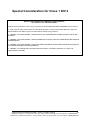
Special Consideration for Class 1 DIV 2
Special Instructions for Installation and Operation
in a Class 1 Div 2 Environment
When this device is operated in a Class 1 Div 2 environment, the following PRECAUTIONS and WARNINGS must be observed:
1. Power, input and output (I/O) wiring must be in accordance with Class 1 Division 2 wiring methods [Article 501.10(B) of the
National Electrical Code, NFPA 70] and in accordance with the authority having jurisdiction.
2. WARNING – EXPLOSION HAZARD – SUBSTITUTION OF ANY COMPONENTS MAY IMPAIR SUITABILITY FOR CLASS 1,
DIVISION 2.
3. WARNING – EXPLOSION HAZARD – WHEN IN HAZARDOUS LOCATIONS, TURN OFF POWER BEFORE REPLACING OR
WIRING MODULES.
4. WARNING – EXPLOSION HAZARD – DO NOT DISCONNECT EQUIPMENT UNLESS POWER HAS BEEN SWITCHED OFF
OR THE AREA IS KNOWN TO BE NON-HAZARDOUS.
5. WARNING – THIS APPARATUS IS SUITABLE FOR USE IN CLASS 1, DIVISION 2, GROUPS A, B, C, AND D, OR
UNCLASSIFIED LOCATIONS.
Manual Documentation Number: ZP9D-115RM-LR-0812
21
B&B Electronics Mfg Co Inc – 707 Dayton Rd - PO Box 1040 - Ottawa IL 61350 - Ph 815-433-5100 - Fax 815-433-5104 – www.bb-elec.com
B&B Electronics – Westlink Commercial Park – Oranmore, Galway, Ireland – Ph +353 91-792444 – Fax +353 91-792445 – www.bb-europe.com
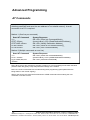
Advanced Programming
AT Commands
Example: Using Hyper Terminal Software to change the module's DT (Destination
Address) parameter and save the new address to non-volatile memory. A serial
connection to a PC is required.
Method 1 (One line per command)
Send AT Command
+++
ATDT <Enter>
ATDT1A0D <Enter>
ATWR <Enter>
ATCN <Enter>
System Response
OK <CR> (Enter into Command Mode)_
{current value} <CR> (Read Destination Address)_
OK <CR> (Modify Destination Address)_
OK <CR> (Write to non-volatile memory)_
OK <CR> (Exit Command Mode)
Method 2 (Multiple commands on one line)
Send AT Command
+++
ATDT <Enter>
ATDT1A0D,WR,CN
<Enter>
System Response
OK <CR> (Enter into Command Mode)
{current value} <CR> (Read Destination Address)
OK <CR> (Execute commands)
Note: When using hyper terminal to program a modem, PC com port settings must match the baud
(interface data rate), parity & stop bits parameter settings of the module.
Note: Do not send commands to the module during flash programming (when parameters are
being written to the module registry).
Wait for the OK sys tem response that follows the ATWR command before entering the next
command or use flow control.
22
Manual Documentation Number: ZP9D-115RM-LR-0812
B&B Electronics Mfg Co Inc – 707 Dayton Rd - PO Box 1040 - Ottawa IL 61350 - Ph 815-433-5100 - Fax 815-433-5104 – www.bb-elec.com
B&B Electronics – Westlink Commercial Park – Oranmore, Galway, Ireland – Ph +353 91-792444 – Fax +353 91-792445 – www.bb-europe.com
Binary Commands
To Send Binary Commands:
Example: Use binary commands to change the RF module's destination address to
0x1A0D and save the new address to non-volatile memory.
RT Command must be set to '1' in AT Command Mode to enable binary
1.
programming.
2.
Assert CMD (Pin 10 is driven high). (Enter Binary Command Mode)
3.
Send Bytes [parameter bytes must be 2 bytes long]:
00
(Send DT (Destination Address) Command)
0D
(Least significant byte of parameter bytes)
1A
(Most significant byte of parameter bytes)
08
(Send WR (Write) Command)
4.
De-assert CMD (pin 10 is driven low). (Exit Binary Command Mode)
Note: CTS (pin 9) is high when a command is being executed. Hardware
flow control must be disabled as CTS will hold off parameter bytes.
Manual Documentation Number: ZP9D-115RM-LR-0812
23
B&B Electronics Mfg Co Inc – 707 Dayton Rd - PO Box 1040 - Ottawa IL 61350 - Ph 815-433-5100 - Fax 815-433-5104 – www.bb-elec.com
B&B Electronics – Westlink Commercial Park – Oranmore, Galway, Ireland – Ph +353 91-792444 – Fax +353 91-792445 – www.bb-europe.com
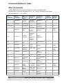
Command Reference Table
Zlinx Commands
(Zlinx Radio Modems expect numerical values in hexadecimal.
Hexadecimal values are designated by a “0x” prefix. Decimal equivalents
are designated by a “d” suffix.)
AT _
Command
Binary _
Command
AT
Command
Name
Parameter
Range
Command _
Category
# Bytes
Returned
Factory
Default
%V
0x3B (59d)
Board
Voltage
0x2CCCA 0x5BFFA
[read-only]
Diagnostics
4
--
AM
0x40 (64d)
Auto-set MY
--
--
--
AP v2.x20*
--
API Enable
0-2
1
0
Command Mode
Options
2
0x0A
(10d)
Serial
Interfacing
4
3
2 - (ATST3)
[x 100
msec]
0-8
(standard
rates)
0x39 0x1C9C38
(nonstandard
rates)
Networking &
Security
Serial
Interfacing
AT
0x05 (5d)
Guard Time
After
BD
0x15 (21d)
Interface
Data Rate
BR
0x39 (57d)
RF Data
Rate
0-1
RF Interfacing
1
1
Guard Time
Before
0 - 0xFFFF
[x 100
msec]
Command Mode
Options
2
0x0A
(10d)
0x20 - 0x7F
Command Mode
Options
1
0x2B
["+"]
(43d)
0-4
Serial
Interfacing
1
2
0-2
Command Mode
Options
1
1
--
Command Mode
Options
--
--
0-4
Serial
Interfacing
1
0
2 - 0xFFFF
[x 100 ms]
Command Mode
Options
2
0xC8
(200d)
0x6E - 0x28
[read-only]
Diagnostics
2
--
2
0
--
--
BT
0x04 (4d)
CC
0x13 (19d)
CD
0x28 (40d)
CF
--
CN
0x09 (9d)
CS
0x1F (31d)
CT
0x06 (6d)
DB
0x36 (54d)
DT
0x00 (0d)
E0
0x0A (10d)
24
Command
Sequence
Character
GPO2
Configuratio
n
Number
Base
Exit
Command
Mode
GPO1
Configuratio
n
Command
Mode
Timeout
Received
Signal
Strength
Destination
Address
Echo Off
0 - 0xFFFF
--
Networking &
Security
Command Mode
Options
Manual Documentation Number: ZP9D-115RM-LR-0812
B&B Electronics Mfg Co Inc – 707 Dayton Rd - PO Box 1040 - Ottawa IL 61350 - Ph 815-433-5100 - Fax 815-433-5104 – www.bb-elec.com
B&B Electronics – Westlink Commercial Park – Oranmore, Galway, Ireland – Ph +353 91-792444 – Fax +353 91-792445 – www.bb-europe.com
E1
0x0B (11d)
Echo On
Receive
Error Count
Force
Wake-up
Initializer
Software
Flow
Control
ER
0x0F (15d)
FH
0x0D (13d)
FL
0x07 (7d)
FS
0x3E (62d)
Forced
Sync Time
FT
0x24 (36d)
Flow
Control
Threshold
GD
0x10 (16d)
Receive
Good Count
Hopping
Channel
--
Command Mode
Options
--
--
0 - 0xFFFF
Diagnostics
2
0
--
Sleep (Low
Power)
--
--
0-1
Serial
Interfacing
1
0
2
0
0 - 0xFFFF
[x 10
msec]
RF
Interfacing
0 - (DI
buffer size 0x11)
[Bytes]
Serial
Interfacing
2
DI buffer
size
minus
0x11
0 - 0xFFFF
Diagnostics
2
0
1
0
2
0xFFFF
(65535d)
Diagnostics
2
--
Networking &
Security
2
0x3332
(13106d)
Networking &
Security
2
0
Sleep (Low
Power)
1
1
HP
0x11 (17d)
HT
0x03 (3d)
Time before
Wake-up
Initializer
HV
--
Hardware
Version
ID
0x27 (39d)
Modem VID
KY
0x3C (60d)
AES
Encryption
Key
LH
0x0C (12d)
Wake-up
Initializer
Timer
0 - 0xFFFF
[read-only]
0x11 0x7FFF
(usersettable)
0x8000 0xFFFF
(factory-set,
read-only)
0 - (Any
other 64digit hex
valid key)
0 - 0xFF
[x 100
msec]
MD v2.x20*
0x31 (49d)
RF Mode
0-6
Networking &
Security
1
0
MK
0x12 (18d)
Address
Mask
0 - 0xFFFF
Networking &
Security
2
0xFFFF
(65535d)
MT
0x3D (61d)
MultiTransmit
0 - 0xFF
Networking &
Security
1
0
MY
0x2A (42d)
Source
Address
0 - 0xFFFF
Networking &
Security
2
0xFFFF
(65535d)
NB
0x23 (35d)
Parity
0-4
Serial
Interfacing
1
0
0x45 (69d)
Polling
Begin
Address
0 - 0xFFFF
Networking &
Security
2
0
0x47 (71d)
Minimum
Polling
Delay
0 - 0xFFFF
_ (Base: (x
1 ms),
Remote: [x
10 ms])
Networking &
Security
2
0
PB v2.x20*
PD v2.x20*
0-9
Networking &
Security
Sleep
[x 100
(Low
msec]
Power
)
0 - 0xFFFF
Manual Documentation Number: ZP9D-115RM-LR-0812
25
B&B Electronics Mfg Co Inc – 707 Dayton Rd - PO Box 1040 - Ottawa IL 61350 - Ph 815-433-5100 - Fax 815-433-5104 – www.bb-elec.com
B&B Electronics – Westlink Commercial Park – Oranmore, Galway, Ireland – Ph +353 91-792444 – Fax +353 91-792445 – www.bb-europe.com
ZP9D-115RM-LR Commands (Zlinx Radio Modems expect numerical values in
hexadecimal. Hexadecimal values are designated by a “0x” prefix. Decimal
equivalents are designated by a “d” suffix.)
AT _
Command
Binary _
Command
PE
v2.x20*
0x46 (70d)
PK
0x29 (41d)
PL
0x3A (58d)
PW
0x1D (29d)
RB
0x20 (32d)
AT
Command
Name
Polling
End
Address
Maximum
RF Packet
Size
TX Power
Level
Pin Wakeup
Packetizati
on
Threshold
Ambient
Power Single
Channel
Restore
Defaults
Ambient
Power - All
Channels
Delay
Slots
Parameter
Range
Command _
Category
# Bytes
Returned
Factory
Default
0 - 0xFFFF
Networking &
Security
2
0
1 - 0x800
[Bytes]
RF Interfacing
2
varies
0-4
RF Interfacing
1
4 (1
Watt)
0-1
Sleep (Low
Power)
1
0
1Current
value of
PK
Serial
Interfacing
2
0x800
(2048d)
0 - 0x31
[dBm,
read-only]
Diagnostics
1
--
--
(Special)
--
--
Diagnostics
2
--
Networking &
Security
1
0
Serial
Interfacing
2
3
Diagnostics
1
0x20
(32d)
RC
--
RE
0x0E (14d)
RM
--
RN
0x19 (25d)
RO
0x21 (33d)
Packetizati
on
Timeout
RP
0x22 (34d)
RSSI PWM
Timer
RR
0x18 (24d)
Retries
0 - 0xFF
Networking &
Security
1
0x0A
(10d)
RT
0x16 (22d)
GPI1
Configurati
on
0-2
Serial
Interfacing
1
0
SB
0x37 (55d)
Stop Bits
0-1
Serial
Interfacing
1
0
Serial
Number
High
Serial
Number
Low
Sleep
Mode
Time
before
Sleep
0 - 0xFFFF
[readonly]
0 - 0xFFFF
[readonly]
0 - 8 (3 is
reserved)
(ATAT+3)
- 0x7FFF
[x 100
Diagnostics
2
varies
Diagnostics
2
varies
Sleep (Low
Power)
1
0
Sleep (Low
Power)
2
0x64
(100d)
SH
0x25 (37d)
SL
0x26 (38d)
SM
0x01 (1d)
ST
0x02 (2d)
26
No
parameter
- 0x7D0
0 - 0xFF
[slots]
0 - 0xFFFF
[x UART
character
time]
0 - 0xFF
[x 100
msec]
Manual Documentation Number: ZP9D-115RM-LR-0812
B&B Electronics Mfg Co Inc – 707 Dayton Rd - PO Box 1040 - Ottawa IL 61350 - Ph 815-433-5100 - Fax 815-433-5104 – www.bb-elec.com
B&B Electronics – Westlink Commercial Park – Oranmore, Galway, Ireland – Ph +353 91-792444 – Fax +353 91-792445 – www.bb-europe.com
msec]
TP
0x38 (56d)
TR
0x1B (27d)
TT
0x1A (26d)
TX
0x3F (63d)
VL
--
VR
0x14 (20d)
WA
--
WN
--
WR
0x08 (8d)
--
WS
Board
Temperatu
re
Delivery
Failure
Count
0 - 0x7F
[readonly]
0 - 0xFFFF
[readonly]
0 - 0xFFFF
[0 =
disabled]
Diagnostics
1
--
Diagnostics
2
0
Networking &
Security
2
0
0-1
RF Interfacing
1
0
Returns
string
Diagnostics
--
--
0 - 0xFFFF
[readonly]
Diagnostics
2
--
Returns
string
Diagnostics
--
--
Returns
string
Diagnostics
--
--
Write
--
(Special)
--
--
Sticky
Warning
Numbers
Returns
string
Diagnostics
--
--
Streaming
Limit
Transmit
Only
Firmware
Version verbose
Firmware
Version
Active
Warning
Numbers
Warning
Data
* Firmware version in which command and parameter options were first supported
Manual Documentation Number: ZP9D-115RM-LR-0812
27
B&B Electronics Mfg Co Inc – 707 Dayton Rd - PO Box 1040 - Ottawa IL 61350 - Ph 815-433-5100 - Fax 815-433-5104 – www.bb-elec.com
B&B Electronics – Westlink Commercial Park – Oranmore, Galway, Ireland – Ph +353 91-792444 – Fax +353 91-792445 – www.bb-europe.com
Command Descriptions
Commands in this section are listed alphabetically. Command categories are
designated between the "< >" symbols that follow each command title. By default,
Zlinx Radio Modems expect numerical values in hexadecimal since the default value
of the CF (Number Base) Parameter is '1'. Hexadecimal values are designated by the
"0x" prefix and decimal values by the "d" suffix.
%V (Board Voltage) Command
<Diagnostics> %V Command is
used to read the current voltage
of the module circuit board.
AT Command: AT%V
Binary Command: 0x3B (59 decimal)
Parameter Range (read-only): 0x2CCCA 0x5BFFA (2.80 - 5.75 decimal)
Sample Output:
5.02 V (when ATCF = 0)
5051F (when ATCF = 1) *
5.02 (when ATCF = 2)
Number of bytes returned: 4
* When CF = 1 (default), a hex integer is shown that is equal to (voltage * 65536d).
AM (Auto-set MY) Command
AT Command: ATAM
<Networking & Security> AM
Binary Command: 0x40 (64 decimal)
Command is used to
automatically set the MY (Source Address)
parameter from the factory-set serial number of the module. The address is formed
with bits 29, 28 and 13-0 of the serial number (in that order). The resulting value is
displayed as a result of this command.
AP (API Enable) Command
<Serial Interfacing> The AP
command is used to enable the
module to operate using the
framebased API operation.
AT Command: ATAP
Parameter Range: 0 - 2
Parameter
Configuration
0
API Disabled
(Transparent
Operation)
1
API enabled (w/out
escaped characters)
2
API enabled (with
escaped characters)
Default Parameter Value:0
Number of Bytes Returned:1
Minimum Firmware Version Required: 2.x20
28
Manual Documentation Number: ZP9D-115RM-LR-0812
B&B Electronics Mfg Co Inc – 707 Dayton Rd - PO Box 1040 - Ottawa IL 61350 - Ph 815-433-5100 - Fax 815-433-5104 – www.bb-elec.com
B&B Electronics – Westlink Commercial Park – Oranmore, Galway, Ireland – Ph +353 91-792444 – Fax +353 91-792445 – www.bb-europe.com
AT (Guard Time After)
Command
<Command Mode Options> AT
Command is used to set/read
the time-of-silence that follows
the command sequence
character (CC Command) of the
AT Command Mode Sequence
(BT + CC + AT). By default, 1
second must elapse before and
after the command sequence
character.
AT Command: ATAT
Binary Command: 0x05 (5 decimal)
Parameter Range: 2 - (ATST-3), up to 0x7FFC
[x 100 milliseconds]
Default Parameter Value: 0x0A (10 decimal)
Number of bytes returned: 2
Related Commands: BT (Guard Time Before),
CC (Command Sequence Character)
The times-of-silence surrounding the command sequence character are used to
prevent inadvertent entrance into AT Command Mode. Refer to the „AT Command
Mode‟ section for more information regarding the AT Command Mode Sequence.
BD (Interface Data Rate)
Command
<Serial Interfacing> The BD
command is used to set and
read the serial interface data
rate (baud rate) used between
the RF module and host. This
parameter determines the rate
at which serial data is sent to
the module from the host.
Modified interface data rates do
not take effect until the CN
(Exit AT Command Mode)
command is issued and the
system returns the 'OK'
response.
When parameters 0-8 are sent
to the module, the respective
interface data rates are used
(as shown in the table on the
right).
The RF data rate is not affected
by the BD parameter. If the
interface data rate is set higher
than the RF data rate, a flow
control configuration may
need to be implemented.
AT Command: ATBD
Binary Command: 0x15 (21 decimal)
Parameter Ranges: 0 - 8 (standard rates)_ 0x39 0x1C9C38 (non-standard rates)
Parameter
Configuration (bps)
0
1200
1
2400
2
4800
3
9600
4
19200
5
38400
6
57600
7
115200
8
230400
Default Parameter Value: 3
Non-standard baud rates supported as of
firmware v2.x20
Number of bytes returned: 4
The range between standard and non-standard baud rates (0x09 - 0x38) is invalid.
Manual Documentation Number: ZP9D-115RM-LR-0812
29
B&B Electronics Mfg Co Inc – 707 Dayton Rd - PO Box 1040 - Ottawa IL 61350 - Ph 815-433-5100 - Fax 815-433-5104 – www.bb-elec.com
B&B Electronics – Westlink Commercial Park – Oranmore, Galway, Ireland – Ph +353 91-792444 – Fax +353 91-792445 – www.bb-europe.com
Non-standard Interface Data Rates:
Any value above 0x38 will be interpreted as an actual baud rate. When a value above
0x38 is sent, the closest interface data rate represented by the number is stored in
the BD register. For example, a rate of 19200 bps can be set by sending the following
command line "ATBD4B00".
When the BD command is sent with a non-standard interface data rate, the UART will
adjust to accommodate the requested interface rate. In most cases, the clock
resolution will cause the stored BD parameter to vary from the parameter that was
sent (refer to the table below). Reading the BD command (send "ATBD" command
without an associated parameter value) will return the value actually stored in the
module‟s BD register.
Parameters Sent Versus Parameters Stored
BD Parameter Sent
Interface Data Rate (bps)
(HEX)
0
1200
BD Parameter Stored (HEX)
0
4
19,200
7
115,200
7
12C
300
12B
1C200
115,200
1B207
BR (RF Data Rate) Command
<RF Interfacing> The BR
command is used to set and
read the RF data rate (rate that
RF data is transmitted over-theair) of the module.
4
AT Command: ATBR
Binary Command: 0x39 (57 decimal)
Parameter Range: 0 - 1
Parameter
Baud (bps)
Configuration
0
9600
1
115200
Default Parameter Value:1
Number of bytes returned: 1
AT Command: ATCC
BT (Guard Time Before)
Command
Binary Command: 0x13 (19 decimal)
<AT Command Mode Options>
Parameter Range: 0x20 - 0x7F
The CC command is used to
set/read the ASCII character
Default Parameter Value: 0x2B (ASCII “+”)
used between guard times of
the AT Command Mode
Number of bytes returned: 1
Sequence (BT + CC + AT).
Related Commands: AT (Guard Time After), BT
This sequence enters the
(Guard Time Before)
module into AT Command
Mode so that data entering the
module (from the host) is recognized as commands instead of payload.
30
Manual Documentation Number: ZP9D-115RM-LR-0812
B&B Electronics Mfg Co Inc – 707 Dayton Rd - PO Box 1040 - Ottawa IL 61350 - Ph 815-433-5100 - Fax 815-433-5104 – www.bb-elec.com
B&B Electronics – Westlink Commercial Park – Oranmore, Galway, Ireland – Ph +353 91-792444 – Fax +353 91-792445 – www.bb-europe.com
Refer to the „AT Command Mode‟ section for more information regarding the AT
Command Mode Sequence.
AT Command: ATCC
CC (Command Sequence
Character) Command
Binary Command: 0x13 (19 decimal)
<AT Command Mode Options>
Parameter Range: 0x20 - 0x7F
The CC command is used to
set/read the ASCII character
Default Parameter Value: 0x2B (ASCII “+”)
used between guard times of
Number of bytes returned: 1
the AT Command Mode
Sequence (BT + CC + AT).
Related Commands: AT (Guard Time After), BT
This sequence enters the
(Guard Time Before)
module into AT Command
Mode so that data entering the module (from the host) is recognized as commands
instead of payload.
Refer to the „AT Command Mode‟ section for more information regarding the AT
Command Mode Sequence.
CD (GPO2 Configuration)
Command
<Serial Interfacing> CD
Command is used to
select/read the behavior of the
GPO2 line (pin 3).
AT Command: ATCD
Binary Command: 0x28 (40 decimal)
Parameter Range: 0 - 8 (standard rates)
Parameter
Configuration
0
RX LED
1
Default High
2
Default Low
3
4
(reserved)
RX LED (valid
address only)
Default Parameter Value: 2
Number of bytes returned: 1
Manual Documentation Number: ZP9D-115RM-LR-0812
31
B&B Electronics Mfg Co Inc – 707 Dayton Rd - PO Box 1040 - Ottawa IL 61350 - Ph 815-433-5100 - Fax 815-433-5104 – www.bb-elec.com
B&B Electronics – Westlink Commercial Park – Oranmore, Galway, Ireland – Ph +353 91-792444 – Fax +353 91-792445 – www.bb-europe.com
CF (Number Base) Command
<Command Mode Options> CF
command is used to set/read the
command formatting setting.
The following commands are
always entered and read in hex,
no matter the CF setting:
VR (Firmware Version)
HV (Hardware Version)
KY (AES Encryption Key)
AT Command: ATCF
Parameter Range: 0 – 2
Parameter
Configuration
0
Commands utilize default
number base; decimal
commands may output units
1
All commands forced to
unsigned, unit-less hex
2
Commands utilize their
default number base; no
units are output
Default Parameter Value: 1
Number of bytes returned: 1
AT Command: ATCN
CN (Exit AT Command Mode)
Command
Binary Command: 0x09 (9 decimal)
<Command Mode Options> The
CN command is used to explicitly exit the module from AT Command Mode.
CS (GPO1 Configuration)
Command
<Serial Interfacing> CS
Command is used to select the
behavior of the GP01 pin (pin
9). This output can provide RS232 flow control, control
the TX enable signal (for RS485 or RS-422 operations).
By default, GP01 provides RS232 CTS (Clear-to- Send) flow
control.
AT Command: ATCS
Binary Command: 0x1F (31 decimal)
Parameter Range: 0 - 4
Parameter
0
1
Configuration
RS-232 CTS flow control
RS-485 TX enable low
2
3
High
RS-485 TX enable high
4
Low
Default Parameter Value: 0
Number of bytes returned: 1
Related Commands: RT (GPI1 Configuration),
TO (GP01 Timeout)
32
Manual Documentation Number: ZP9D-115RM-LR-0812
B&B Electronics Mfg Co Inc – 707 Dayton Rd - PO Box 1040 - Ottawa IL 61350 - Ph 815-433-5100 - Fax 815-433-5104 – www.bb-elec.com
B&B Electronics – Westlink Commercial Park – Oranmore, Galway, Ireland – Ph +353 91-792444 – Fax +353 91-792445 – www.bb-europe.com
CT (Command Mode Timeout)
Command
<Command Mode Options> The
CT command is used to set and
read the amount of inactive time
that elapses before the module
automatically exits from AT
Command Mode and returns to
Idle Mode.
Use the CN (Exit AT Command
Mode) command to exit AT
Command Mode manually.
AT Command: ATCT
Binary Command: 0x06 (6 decimal)
Parameter Range: 2 - 0xFFFF [x 100
milliseconds]
Default Parameter Value: 0xC8 (200d)
Number of bytes returned: 2
Related Command: CN (Exit AT Command
Mode)
DB (Received Signal Strength)
AT Command: ATDB
Command
Binary Command: 0x36 (54 decimal)
<Diagnostics> DB Command is
used to read the receive signal
Parameter Range (read-only): 0x6E - 0x28 (-110
strength (in decibels relative to
to -40 Decimal)
milliWatts) of the last received
Number of bytes returned: 2
packet. This parameter is useful
in determining range characteristics of the Zlinx Radio Modems under various
conditions.
In default mode, this command shows the power level in signed decimal format with
the units (dBm). If CF = 1, the magnitude of the value is presented in unsigned hex. If
CF = 2, the value is presented in decimal, but without the units.
Sample Output: -88 dBm(when ATCF = 0)
58 (when ATCF = 1)
-88 (when ATCF = 2)
NOTE: If the DB register is read before the module has received an RF packet, the
module will return a value of 0x8000 (which means an RF packet has not yet been
received).
DT (Destination Address)
AT Command: ATDT
Command
Binary Command: 0x00
<Networking & Security> DT
Command is used to set/read
Parameter Range: 0 - 0xFFFF
the networking address of an RF
module. The modules utilize
Default Parameter Value: 0
three filtration layers: Vendor
Number of bytes returned: 2
ID Number (ATID), Channel
(ATHP), and Destination
Related Commands: HP (Hopping Channel), ID
Address (ATDT). The DT
(Modem VID), MK (Address Mask), MY (Source
command assigns an address to
Address)
a module that enables it to
communicate only with other modules having the same address. All modules that
share the same DT parameter can communicate with each other.
Zlinx Radio Modems in the same network with a different destination address (than
that of the transmitter) will listen to all transmissions to stay synchronized, but will not
send any of the data out their serial ports.
Manual Documentation Number: ZP9D-115RM-LR-0812
33
B&B Electronics Mfg Co Inc – 707 Dayton Rd - PO Box 1040 - Ottawa IL 61350 - Ph 815-433-5100 - Fax 815-433-5104 – www.bb-elec.com
B&B Electronics – Westlink Commercial Park – Oranmore, Galway, Ireland – Ph +353 91-792444 – Fax +353 91-792445 – www.bb-europe.com
E0 (Echo Off) Command
<Command Mode Options> E0
Command turns off character
echo in AT Command Mode.
AT Command: ATE0
Binary Command: 0x0A (10 decimal)
By default, echo is off.
E1 (Echo On) Command
AT Command: ATE1
<Command Mode Options> E1
Command enables character
Binary Command: 0x0B (11 decimal)
echo in AT Command Mode.
Each typed character will be echoed back to the terminal when ATE1 is active.
E0 (Echo Off) is the default.
AT Command: ATER
ER (Receive Error Count)
Command
Binary Command: 0x0F (15 decimal)
<Diagnostics> The ER
Parameter Range: 0 - 0xFFFF
command is used to set/read
the number of receive-errors.
Default Parameter Value: 0
The error count records the
Number of bytes returned: 2
number of packets partially
received then aborted on a
Related Commands: GD (Receive Good Count)
reception error. This value
returns to 0 after a reset and is not nonvolatile (Value does not persist in the module's
memory after a power-up sequence). Once the Receive Error Count reaches its
maximum value (up to 0xFFFF), it remains at its maximum count value until the
maximum count value is explicitly changed or the module is reset.
The ER parameter is not reset
AT Command: ATFH
by pin, serial port or cyclic sleep
modes.
Binary Command: 0x0D (13 decimal)
FH (Force Wake-up Initializer)
Command
<Sleep (Low Power)> The FH command is used to force a Wake-up Initializer to be
sent on the next transmission. Use only with cyclic sleep modes active on remote
modules.
ATFH will not send a long header if ATHT = 0xFFFF. WR (Write) Command does not
need to be issued with FH Command.
FL (Software Flow Control)
Command
<Serial Interfacing> The FL
command is used to configure
software flow control. Hardware
flow control is implemented with
the module as the GP01 pin
(CTS pin of the OEM RF
module), which regulates when
serial data can be transferred to
the module.
AT Command: ATFL
Binary Command: 0x07 (7 decimal)
Parameter Range: 0 - 1
Parameter
Configuration
0
Disable software flow
control
1
Enable software flow
control
Default Parameter Value: 0
FL Command can be used to
allow software flow control to
Number of bytes returned: 1
also be enabled. The XON
character used is 0x11 (17 decimal). The XOFF character used is 0x13 (19 decimal)
34
Manual Documentation Number: ZP9D-115RM-LR-0812
B&B Electronics Mfg Co Inc – 707 Dayton Rd - PO Box 1040 - Ottawa IL 61350 - Ph 815-433-5100 - Fax 815-433-5104 – www.bb-elec.com
B&B Electronics – Westlink Commercial Park – Oranmore, Galway, Ireland – Ph +353 91-792444 – Fax +353 91-792445 – www.bb-europe.com
AT Command: ATFS
FS (Forced Synch Time)
Command
Binary Command: 0x3E (62 decimal)
<RF Interfacing> The FS
Parameter Range: 0 - 0xFFFF [x 10
command only applies to
milliseconds]
streaming data. Normally, only
the first packet of a continuous
Default Parameter Value: 0
stream contains the full RF
initializer. Zlinx Radio Modems
Number of bytes returned: 2
then remain synchronized for
subsequent packets of the stream. This parameter can be used to periodically force
an RF initializer during such streaming. Any break in UART character reception long
enough to drain the DI Buffer (UART receive buffer) and cause a pause in RF data
transmission will also cause an RF initializer to be inserted on the next transmission.
FT (Flow Control Threshold)
Command
<Serial Interfacing> The FT
command is used to set/read
the flow control threshold. When
FT
bytes have accumulated in the
DI buffer (UART Receive), CTS
is de-asserted or the XOFF
software flow control character
is transmitted.
AT Command: ATFT
Binary Command: 0x24 (36 decimal)
Parameter Range: 0 - (DI buffer size minus
0x11) [Bytes]
Default Parameter Value: DI Buffer size minus
0x11 (17 decimal)
Number of bytes returned: 2
AT Command: ATGD
GD (Receive Good Count)
Command
Binary Command: 0x10 (16 decimal)
<Diagnostics> The GD
Parameter Range: 0 - 0xFFFF
command is used to set/
read the count of good received
Default Parameter Value: 0
RF packets. Its parameter value
Number of bytes returned: 2
is reset to 0 after every reset
and is not non-volatile (The
Related Commands: ER (Receive Error Count)
parameter value does not
persist in the RF module's memory after a power-up sequence). Once the "Receive
Good Count" reaches its maximum value (up to 0xFFFF), it remains at its maximum
count value until the maximum count value is manually changed or the module is
reset.
The GD parameter is not reset by pin, serial port or cyclic sleep modes.
Manual Documentation Number: ZP9D-115RM-LR-0812
35
B&B Electronics Mfg Co Inc – 707 Dayton Rd - PO Box 1040 - Ottawa IL 61350 - Ph 815-433-5100 - Fax 815-433-5104 – www.bb-elec.com
B&B Electronics – Westlink Commercial Park – Oranmore, Galway, Ireland – Ph +353 91-792444 – Fax +353 91-792445 – www.bb-europe.com
HP (Hopping Channel)
Command
<Networking & Security> The
HP command is used to
set/read the RF module's
hopping channel number. A
channel is one of three layers of
filtration available to the
module.
AT Command: ATHP
Binary Command: 0x11 (17 decimal)
Parameter Range: 0 - 9
Default Parameter Value: 0
Number of bytes returned: 1
Related Commands: ID (Modem VID), DT
(Destination Address), MK (Address Mask)
In order for modules to
communicate with each other, the modules must have the same channel number
since each channel uses a different hopping sequence. Different channels can be
used to prevent modules in one network from listening to transmissions of another.
HT (Time before Wake-up
AT Command: ATHT
Initializer) Command
Binary Command: 0x03 (3 decimal)
<Sleep (Low Power)> The HT
command is used to set/read
Parameter Range: 0 - 0xFFFF [x 100
the time of inactivity (no serial or
milliseconds]
RF
Default Parameter Value: 0xFFFF (wake-up
data is sent or received) before
initializer will not be sent)
a wake-up initializer is sent by a
TX (transmitting) RF module.
Number of bytes returned: 2
The HT parameter should be set
shorter than inactivity timeout
Related Commands: LH (Wake-up Initializer
[ST Command] time of any RX
Timer), SM (Sleep Mode), ST (Time before
(receiving) modules operating in
Sleep)
Cyclic Sleep (SM=4-8). The
wake-up initializer sent by the TX module instructs all RX modules to remain awake to
receive RF data.
From the RX module perspective: After HT time elapses and the inactivity timeout [ST
Command] is met, the RX module goes into cyclic sleep. In cyclic sleep, the RX
module wakes once per sleep interval [SM Command] to check for a wake-up
initializer. When a wake-up initializer is detected, the module stays awake to receive
data. The wake-up initializer must be longer than the cyclic sleep interval to ensure
that sleeping modules detect incoming data.
When HT time elapses, the TX module knows it needs to send a wake-up Initializer
for all RX modules to remain awake and receive the next transmission.
AT Command: ATHV
HV (Hardware Version)
Command
Parameter Range: 0 - 0xFFFF [Read-only]
<Diagnostics> The HV
command is used to read the hardware version of the RF module.
36
Manual Documentation Number: ZP9D-115RM-LR-0812
B&B Electronics Mfg Co Inc – 707 Dayton Rd - PO Box 1040 - Ottawa IL 61350 - Ph 815-433-5100 - Fax 815-433-5104 – www.bb-elec.com
B&B Electronics – Westlink Commercial Park – Oranmore, Galway, Ireland – Ph +353 91-792444 – Fax +353 91-792445 – www.bb-europe.com
ID (Modem VID) Command
<Networking & Security> The ID
command is used to set/read
the VID (Vendor Identification
Number) of the RF module.
Zlinx Radio Modems must have
matching VIDs in order to
communicate.
AT Command: ATID
Binary Command: 0x27 (39 decimal)
Parameter Range: 0x11 - 0x7FFF (user-settable)
0 - 0x10 & 0x8000 - 0xFFFF (factory-set)
Default Parameter Value: 0x3332 (13106d)
Number of bytes returned: 2
KY (AES Encryption Key)
AT Command: ATKY
Command
Binary Command: 0x3C (60 decimal)
<Networking & Security> The KY
command is used to set the 256Parameter Range: 0 - (any other 64-digit hex
bit AES (Advanced Encryption
valid key)
Standard) key for
Default Parameter Value: 0 (disabled)
encrypting/decrypting data.
Once set, the key cannot be
Number of bytes returned: 2
read out of the module by any
means. The entire payload of the
Number Base: Always Hexadecimal
packet is encrypted using the
key and the CRC is computed across the ciphertext. When encryption is enabled,
each packet carries an additional 16 bytes to convey the random CBC Initialization
Vector (IV) to the receiver(s). The KY value may be “0” or any 256-bit value (= 64 hex
digits = 32 bytes). Any other value, including entering ATKY by itself with no
parameters, causes an error.
A module with the wrong key (or no key) will receive encrypted data, but the data
driven out the serial port will be meaningless. Likewise, a module with a key will
receive unencrypted data sent from a module without a key, but the output will be
meaningless. Because CBC mode is utilized, repetitive data appears differently in
different transmissions due to the randomly-generated IV.
Manual Documentation Number: ZP9D-115RM-LR-0812
37
B&B Electronics Mfg Co Inc – 707 Dayton Rd - PO Box 1040 - Ottawa IL 61350 - Ph 815-433-5100 - Fax 815-433-5104 – www.bb-elec.com
B&B Electronics – Westlink Commercial Park – Oranmore, Galway, Ireland – Ph +353 91-792444 – Fax +353 91-792445 – www.bb-europe.com
AT Command: ATLH
LH (Wake-up Initializer Timer)
Command
Binary Command: 0x0C (12 decimal)
<Sleep (Low Power)> The LH
Command is used to set/read
Parameter Range: 0 - 0xFF [x 100 milliseconds]
the duration of time during which
the wake-up initializer is sent.
Default Parameter Value: 1
When receiving modules are in
Cyclic Sleep Mode, they powerNumber of bytes returned: 1
down after a period of inactivity
Related Commands: HT (Time before Wake-up
(as specified by the ST
Initializer), SM (Sleep Mode), ST (Time before
parameter) and will periodically
Sleep)
wake and listen for transmitted
data. In order for the receiving
modules to remain awake, they must detect ~35ms of the wake-up initializer.
LH Command must be used whenever a receiving module is operating in Cyclic Sleep
Mode. The Wake-up Initializer Time must be longer than the cyclic sleep time that [as
determined by SM (Sleep Mode) parameter]. If the wake-up initializer time were less
than the Cyclic Sleep interval, the connection would be at risk of missing the wake-up
initializer transmission.
Refer to figures located under the SM command description to view diagrams of
correct and incorrect configurations. The images emphasize that the LH value must
be greater than the SM value.
MD (RF Mode) Command
<Networking & Security> The
MD command is used to
select/read the settings that
enable the Polling and Repeater
Modes on the module.
Polling Mode - A „Polling Base‟
is responsible for polling
remotes. A „Polling Remote‟
requires a poll in order to
transmit.
Repeater Mode - A „Repeater‟
re-sends RF data unless the
transmission is addressed to it or
if the transmission has already
been detected. A „Repeater End
Node‟ handles repeated
messages, but will not repeat the
message over-the-air.
AT
Command:
ATMD
Binary Command: 0x31 (49 decimal)
Parameter
Range:
0-6
Parameter
Configuration
0
Transparent Operation
(Repeater Base)
1
[reserved - not used]
2
[reserved - not used]
3
Polling Base
4
Polling Remote
5
Repeater
6
Repeater End Node
Default Parameter Value:
0
Number of bytes returned: 1
Refer to the Polling and
Minimum Firmware Version Required: 2.x20
Repeater Mode sections of
the „RF Communication Modes‟ chapter for more information.
38
Manual Documentation Number: ZP9D-115RM-LR-0812
B&B Electronics Mfg Co Inc – 707 Dayton Rd - PO Box 1040 - Ottawa IL 61350 - Ph 815-433-5100 - Fax 815-433-5104 – www.bb-elec.com
B&B Electronics – Westlink Commercial Park – Oranmore, Galway, Ireland – Ph +353 91-792444 – Fax +353 91-792445 – www.bb-europe.com
AT Command: ATMK
MK (Address Mask) Command
<Networking & Security> The MK
Binary Command: 0x12 (18 decimal)
command is used to set/read the
Parameter Range: 0 - 0xFFFF
Address Mask of a module.
All RF data packets contain the
Default Parameter Value: 0xFFFF (65535d)
Destination Address of the TX
Number of bytes returned: 2
(transmitting) module. When a
packet is received, the TX
Related Commands: DT (Destination Address),
module Destination Address is
HP (Hopping Channel), ID (Modem VID), MY
logically "ANDed" (bitwise) with
(Source Address)
the Address Mask of the RX
(receiving) module. The resulting value must match the Destination Address or
Address Mask of the RX module for the packet to be received and sent out the RX
module's DO (Data Out) pin. If the "ANDed" value does not match the Destination
Address or Address Mask of the RX module, the packet is discarded.
Sniffer Mode (when MK = 0): ACK requests are ignored and every RX (receive)
frame is sent to the UART, without regard for repeated frames. All “0” values are
treated as irrelevant values and ignored.
MT (Multi-transmit) Command
<Networking & Security> The
MT command is used to enabled
multiple transmissions of RF
data packets. When Multitransmit Mode is enabled (MT >
0), packets do not request an
ACK (acknowledgement) from
the receiving RF module(s). MT
takes precedence over RR, so if
both MT and RR are non-zero,
then MT+1 packets will be sent
(with no ACK requests).
AT Command: ATMT
Binary Command: 0x3D (61 decimal)
Parameter Range: 0 - 0xFF
Default Parameter Value:0 (no forced
retransmissions)
Number of bytes returned: 1
Related Commands: Networking (DT, MK, MY,
RN, TT), Serial Interfacing (BR, PK, RB, RO),
RF Interfacing (FS)
When a receiving module receives a packet with remaining forced retransmissions, it
calculates the length of the packet and inhibits transmission for the amount of time
required for all retransmissions. Thereafter, a random number of delay slots are
inserted between 0 and RN before transmission is allowed from the receiving
module(s). This prevents all listening modules from transmitting at once upon
conclusion of a multiple transmission event (when RN > 0).
NOTE: The actual number of forced transmissions is the parameter value plus one.
For example, if MT = 1, two transmissions of each packet will be sent.
Manual Documentation Number: ZP9D-115RM-LR-0812
39
B&B Electronics Mfg Co Inc – 707 Dayton Rd - PO Box 1040 - Ottawa IL 61350 - Ph 815-433-5100 - Fax 815-433-5104 – www.bb-elec.com
B&B Electronics – Westlink Commercial Park – Oranmore, Galway, Ireland – Ph +353 91-792444 – Fax +353 91-792445 – www.bb-europe.com
MY (Source Address)
Command
<Networking & Security> The
MY command is used to set/read
the Source Address of the RF
module.
AT Command: ATMY
Binary Command: 0x2A (42 decimal)
Parameter Range: 0 - 0xFFFF
Default Parameter Value: 0xFFFF (Disabled DT (Destination Address) parameter serves as
both source and destination address.)
Number of bytes returned: 2
Related Commands: DT (Destination Address),
HP (Hopping Channel), ID (Modem VID), MK
(Address Mask)
NB (Parity) Command
<Serial Interfacing> The NB
command is used to select/read
the parity settings of the RF
module for UART
communications.
AT
ATNB
Command:
Binary Command: 0x23 (35 decimal)
Parameter
0-4
Range:
Parameter
Configuration
0
8-bit (no parity or 7-bit
(any parity)
1
8-bit even
2
8-bit odd
3
8-bit mark
4
Default Parameter Value:
8-bit space
0
Number of bytes returned: 1
PB (Polling Begin Address)
Command
<Networking & Security> PB
command is used to set/read the
module‟s Polling Begin Address
– the first address polled Polling
Mode is enabled.
AT Command: ATPB
Binary Command: 0x45 (69 decimal)
Parameter Range: 0 - 0xFFFF
Default Parameter Value: 0
Number of bytes returned: 2
Minimum Firmware Version Required: 2.x20
Polling Operations: The „Polling
Related Commands: MD (RF Mode), PE
Base‟ (MD = 3) cycles through a
(Polling End Address), PD (Minimum Polling
sequential range of addresses,
Delay)
polling each „Polling Remote‟
(MD = 4). The base then waits for a response & proceeds to the next „Polling
Remote‟. Each „Polling Remote‟ responds by sending the data from the Data In buffer
following the RB & RO parameters. When there is no eligible data to send, the „Polling
Remote‟ will not respond. The „Polling Base‟ will move to the next address in the
polling sequence after a short delay.
40
Manual Documentation Number: ZP9D-115RM-LR-0812
B&B Electronics Mfg Co Inc – 707 Dayton Rd - PO Box 1040 - Ottawa IL 61350 - Ph 815-433-5100 - Fax 815-433-5104 – www.bb-elec.com
B&B Electronics – Westlink Commercial Park – Oranmore, Galway, Ireland – Ph +353 91-792444 – Fax +353 91-792445 – www.bb-europe.com
PD (Minimum Polling Delay)
Command
<Networking & Security> The PD
command is used to set/read
Polling Delay (Base, MD=3) or
Polling Timeout (Remote,
MD=4).
AT Command: ATPD
Binary Command: 0x47 (71 decimal)
Parameter Range: 0 - 0xFFFF_ (Base: [x 1ms],
Remote: [x 10ms])
Default Parameter Value: 0
Number of bytes returned: 2
Polling Delay (Base) is the time
between polling cycles. The
Polling Base will start the polling
cycle after sending the first poll.
After the polling cycle has
completed, the timer is restarted.
Minimum Firmware Version Required: 2.x20
Related Commands: MD (RF Mode), PB
(Polling Begin Address), PE (Polling End
Address)
Polling Timeout (Remote) is the amount of time the remote unit will hold data from
the serial port before discarding it. Data entered within the PD time of the poll is
transmitted and not discarded.
PE (Polling End Address)
Command
<Networking & Security> PE
command is used to set/read the
module‟s Polling End Address –
the last address polled when
Polling Mode is enabled.
AT Command: ATPE
Binary Command: 0x46 (70 decimal)
Parameter Range: 0 - 0xFFFF
Default Parameter Value: 0
Number of bytes returned: 2
Minimum Firmware Version Required: 2.x20
Polling Operations: The „Polling
Related Commands: MD (RF Mode), PB
Base‟ (MD = 3) cycles through a
(Polling Begin Address), PD (Minimum Polling
sequential range of addresses,
Delay)
polling each „Polling Remote‟
(MD = 4). The base then waits for a response & proceeds to the next „Polling
Remote‟. Each „Polling Remote‟ responds by sending data from the DI buffer following
the RB & RO parameters. When there is no eligible data to send, the „Polling Remote‟
will not respond. The „Polling Base‟ will move to the next address in the polling
sequence after a short delay.
PK (Maximum RF Packet Size)
Command
<RF Interfacing> The PK
command is used to set/read
the maximum size of RF
packets transmitted from an RF
module. The maximum packet
size can be used along with the
RB and RO parameters to
implicitly set the channel dwell
time.
AT Command: ATPK
Binary Command: 0x29 (41 decimal)
Parameter Range: 1 - 0x800 [Bytes]
Default Parameter Value:0x100* or 0x800* (256
or 2048 decimal)
Number of bytes returned: 2
Related Commands: BR (RF Data Rate) RB
(Packetization Threshold), RO (Packetization
Timeout), WN (Warning Data)
If PK is set above 256 and BR is subsequently changed to 0, PK will automatically be
lowered to 256 and a warning will be raised (refer to the BR (RF Data Rate) and WN
(Warning Data) commands for details).
Manual Documentation Number: ZP9D-115RM-LR-0812
41
B&B Electronics Mfg Co Inc – 707 Dayton Rd - PO Box 1040 - Ottawa IL 61350 - Ph 815-433-5100 - Fax 815-433-5104 – www.bb-elec.com
B&B Electronics – Westlink Commercial Park – Oranmore, Galway, Ireland – Ph +353 91-792444 – Fax +353 91-792445 – www.bb-europe.com
Changes to the PK parameter may have a secondary effect on the RB (Packetization
Threshold) parameter. RB must always be less than or equal to PK. If PK is changed
to a value that is less than the current value of RB, the RB value is automatically
lowered to be equal to PK.
* When BR = 0 (9600 baud), the maximum PK value is 0x100 (256d). When BR = 1
(115,200 baud), the maximum PK value is 0x800 (2048d).
PL (TX Power Level)
Command
<RF Interfacing> The PL
command is used to set/
read the power level at which the
RF module transmits data
AT Command: ATPL
Binary Command: 0x3A (58 decimal)
Parameter
Range:
0-4
Parameter
Configuration
0
1 mW
1
10 mW
2
100 mW
3
500 mW
4
1000 mW (1 Watt)
Default Parameter Value: 4
Number of bytes returned: 1
PW (Pin Wake-up) Command
<Sleep (Low Power)> Under
normal operation, an RF module
in Cyclic Sleep Mode cycles from
an active state to a low-power
state at regular intervals until
data is ready to be received. If
the PW parameter is set to 1, the
SLEEP pin (pin 8) can be used
to awaken the module from
Cyclic Sleep. When the SLEEP
Pin is de-asserted (low), the
module will be fully operational
and will not go into Cyclic Sleep.
AT
Command:
ATPW
Binary Command: 0x1D (29 decimal)
Parameter
Range:
0-1
Parameter
Configuration
0
Disabled
1
Default Parameter Value:
Enabled
0
Number of bytes returned: 1
Related Commands: SM (Sleep Mode), ST
(Time before Sleep)
Once the SLEEP pin is asserted,
the module will remain active for
the period of time specified by the ST (Time before Sleep) parameter and will return
to Cyclic Sleep Mode (if no data is ready to be transmitted). PW Command is only
valid if Cyclic Sleep has been enabled.
42
Manual Documentation Number: ZP9D-115RM-LR-0812
B&B Electronics Mfg Co Inc – 707 Dayton Rd - PO Box 1040 - Ottawa IL 61350 - Ph 815-433-5100 - Fax 815-433-5104 – www.bb-elec.com
B&B Electronics – Westlink Commercial Park – Oranmore, Galway, Ireland – Ph +353 91-792444 – Fax +353 91-792445 – www.bb-europe.com
AT Command: ATRB
RB (Packetization Threshold)
Command
Binary Command: 0x20 (32 decimal)
<Serial Interfacing> The RB
Parameter Range: 0 - PK parameter value (up
command is used to set/read the
to 0x800 Bytes)
character threshold value.
RF transmission begins after
Default Parameter Value: 0x800 Bytes
data is received in the DI Buffer
and either of the following criteria
Number of bytes returned: 2
is met:
• RB characters received by
Related Commands: BR (RF Data Rate), PK
the UART
(RF Packet Size), RO (Packetization Timeout)
• RO character times of
silence detected on the UART receive lines (after receiving at least 1 Byte of
data)
If PK (Max. RF Packet Size) is lowered below the value of RB, RB is automatically
lowered to match the PK value. If (RO = 0), RB bytes must be received before
beginning transmission.
Note: RB and RO criteria only apply to the first packet of a multi-packet transmission.
If data remains in the DI Buffer after the first packet, transmissions will continue in a
streaming manner until there is no data left in the DI Buffer (UART receive buffer).
RC (Ambient Power - Single
Channel) Command
<Diagnostics> The RC
command is used to examine
and report the power level on a
given channel.
AT Command: ATRC
Parameter Range (read-only): 0 - 0x31 [dBm]
Number of bytes returned: 1
Related Commands: RM (Ambient Power - All
Channels)
Sample output: -78 dBm [when CF = 0]
4e [when CF = 1]
-78 [when CF = 2]
AT Command: ATRE
RE (Restore Defaults)
Command
Binary Command: 0x0E (14 decimal)
<Diagnostics> The RE command
is used to restore all configurable parameters to their factory default settings.
The RE Command does not cause default values to be stored to non-volatile
(persistent) memory. For the restored default settings to persist in the module‟s nonvolatile memory and be saved in the event of RF module reset or power-down, the
WR (Write) command must be issued prior to power-down or reset.
RM (Ambient Power - All
Channels) Command
<Diagnostics> The RM command
is used to examine and report
power levels on all channels.
If no parameter is given, the
channels are scanned one time. If
a parameter is given, the
AT Command: ATRM
Parameter Range: no parameter - 0x7D0)
Number of bytes returned: 2
Related Commands: RC (Ambient Power Single channel)
Manual Documentation Number: ZP9D-115RM-LR-0812
43
B&B Electronics Mfg Co Inc – 707 Dayton Rd - PO Box 1040 - Ottawa IL 61350 - Ph 815-433-5100 - Fax 815-433-5104 – www.bb-elec.com
B&B Electronics – Westlink Commercial Park – Oranmore, Galway, Ireland – Ph +353 91-792444 – Fax +353 91-792445 – www.bb-europe.com
channels are repeatedly scanned for that number of seconds. The maximum power
level seen for each channel is reported (i.e. peak hold).
A graphical spectrum analyzer can be implemented by repeatedly sending the RM
command (with no arguments) and reading the resultant 50 power levels (this is
easiest to do when CF = 1 or 2).
Sample output [when CF = 0]: Ch 0: -100 dBm
Ch 1: -103 dBm
...
Ch 49: -99 dBm
Sample output [when CF = 1]: 64
67
...
63
Sample output [when CF = 2]: 100
-103
…
-99
RN (Delay Slots) Command
AT Command: ATRN
<Networking & Security> The
Binary Command: 0x19 (25 decimal)
RN command is used to set/read
the time delay that the
Parameter Range: 0 - 0xFF [38 ms slots]
transmitting RF module inserts
Default Parameter Value: 0 (no delay slots
before attempting to resend a
inserted)
packet. If the transmitting
module fails to receive an
Number of bytes returned: 1
acknowledgement after sending
a packet, it inserts a random
Related Commands: RR (Retries), TT
number of delay slots (ranging
(Streaming Limit)
from 0 to (RN minus 1)) before
attempting to resend the packet. Each delay slot is 5 msec (when BR=1) and 54 msec
(when BR=0).
If two modules attempt to transmit at the same time, the random time delay after
packet failure allows only one module to transmit the packet successfully; while the
other module waits until the channel available for RF transmission.
RN Command is only applicable if retries have been enabled [RR (Retries)
Command] or if forced delays will be inserted into a transmission [TT (Streaming
Limit) Command].
RO (Packetization Timeout)
Command
<Serial Interfacing> The RO
command is used to set/read the
Packetization Timeout setting.
RF transmission begins when
data is in the DI buffer and either
of the following criteria are met:
AT Command: ATRO
• RO character times of silence
on the UART receive lines (after
receiving at least 1 byte)
Related Commands: RB (Packetization
Threshold)
44
Binary Command: 0x21 (33 decimal)
Parameter Range: 0 - 0xFFFF [ x UART
character times ]
Default Parameter Value: 3
Number of bytes returned: 2
Manual Documentation Number: ZP9D-115RM-LR-0812
B&B Electronics Mfg Co Inc – 707 Dayton Rd - PO Box 1040 - Ottawa IL 61350 - Ph 815-433-5100 - Fax 815-433-5104 – www.bb-elec.com
B&B Electronics – Westlink Commercial Park – Oranmore, Galway, Ireland – Ph +353 91-792444 – Fax +353 91-792445 – www.bb-europe.com
• RB characters have been received by the UART
RB and RO criteria only apply to the first packet of a multi-packet transmission. If data
remains in the DI Buffer (UART receive) after the first packet, transmissions will
continue in a streaming manner until there is no data left in the DI Buffer.
When RO is the transmission-beginning criteria: The actual time between the
reception of the last character from the UART and the beginning of RF transmission
will be at least 800 µsec longer than the actual RO time to allow for transmission
setup. Additionally, it is subject to 100-200 µsec of additional uncertainty, which could
be significant for small values of RO at high UART bit rates.
The correct UART character time (10, 11, or 12 bits) is calculated based on the
following criteria:
• 1 start bit
• 8 data bits
• 0 or 1 parity bit [as determined by the NB (Parity) Command)
• 1 or 2 stop bits [as determined by SB (Stop Bits) Command]
RP (RSSI PWM Timer)
AT Command: ATRP
Command
Binary Command: 0x22 (34 decimal)
<Diagnostics> RP Command is
used to enable a PWM ("Pulse
Parameter Range: 0 - 0xFF [x 100 milliseconds]
Width Modulation") output on the
Config/RSSI pin (pin 11 of the
Default Parameter Value: 0x20 (32d)
OEM RF Module). The pin is
calibrated to show the difference
Number of bytes returned: 1
between received signal strength
and the sensitivity level of the RF module. PWM pulses vary from zero to 95 percent.
Zero percent means the received RF signal is at or below the published
sensitivity level of the module.
The following table shows dB levels above sensitivity and PWM values (The total time
period of the PWM output is 8.32 ms. PWM output consists of 40 steps and therefore
the minimum step size is 0.208 ms.):
PWM Values
dBm above sensitivity
PWM percentage (high period / total period)
10
20%
20
35%
30
50%
A non-zero value defines the time that PWM output is active with the RSSI value of
the last received RF packet. After the set time when no RF packets are received,
PWM output is set low (0 percent PWM) until another RF packet is received. PWM
output is also set low at power-up. A parameter value of 0xFF permanently enables
PWM output and always reflects the value of the last received RF packet.
The Config/RSSI pin is shared between PWM output and Config input. When the
module is powered, the Config pin is an input. During the power-up sequence, if RP
Manual Documentation Number: ZP9D-115RM-LR-0812
45
B&B Electronics Mfg Co Inc – 707 Dayton Rd - PO Box 1040 - Ottawa IL 61350 - Ph 815-433-5100 - Fax 815-433-5104 – www.bb-elec.com
B&B Electronics – Westlink Commercial Park – Oranmore, Galway, Ireland – Ph +353 91-792444 – Fax +353 91-792445 – www.bb-europe.com
parameter is a non-zero value, the Config pin is configured as an output and set low
until the first RF packet is received. With a non-zero RP parameter, the Config pin is
an input for RP ms after power up.
RR (Retries) Command
<Networking & Security> The
RR command is used to set/read
the maximum number of retries
sent for a given RF packet.
When RR Command is enabled
(RR>0), RF packet retries and
ACKs (acknowledgements) are
enabled.
AT Command: ATRR
Binary Command: 0x18 (24 decimal)
Parameter Range: 0 - 0xFF
Default Parameter Value: 0x0A (10 decimal)
Number of bytes returned: 1
Exceptions: If the MT command in enabled (MT>0) or if a broadcast Destination
Address is used (DT = 0xFFFF); RF packet retries and ACKs are disabled.
After transmitting a packet, the transmitting RF module waits to receive an
acknowledgement from a receiving module. If the acknowledgement is not received in
the period of time specified by RN (Delay Slots) Command, the original packet is
transmitted again. The RF packet is transmitted repeatedly until an acknowledgement
is received or until the packet is sent RR times.
RT (GPI1 Configuration)
Command
<Serial Interfacing> The RT
command is used to set/read the
behavior of the GPI1 pin (pin 10)
of the OEM RF Module. The pin
can be configured to enable
binary programming or RTS flow
control.
AT
Command:
ATRT
Binary Command: 0x16 (22 decimal)
Parameter
Range:
0-2
Parameter
Configuration
0
Disabled
Enable Binary
Programming
1
Enable RTS Flow
Control
2
Default Parameter Value:
0
Number of bytes returned: 1
SB (Stop Bits) Command
<Serial Interfacing> The SB
Command is used to set/read
the number of stop bits in the
data packet.
AT
Command:
ATSB
Binary Command: 0x37 (55 decimal)
Parameter
Range:
0-1
Parameter
Configuration
0
1 stop bit
1
2 stop bits
Default Parameter Value:
0
Number of bytes returned: 1
46
Manual Documentation Number: ZP9D-115RM-LR-0812
B&B Electronics Mfg Co Inc – 707 Dayton Rd - PO Box 1040 - Ottawa IL 61350 - Ph 815-433-5100 - Fax 815-433-5104 – www.bb-elec.com
B&B Electronics – Westlink Commercial Park – Oranmore, Galway, Ireland – Ph +353 91-792444 – Fax +353 91-792445 – www.bb-europe.com
SH (Serial Number High)
Command
<Diagnostics> SH Command is
used to set/read the serial
number high word of the RF
module.
AT Command: ATSH
Binary Command: 0x25 (37 decimal)
Parameter Range (read-only): 0 - 0xFFFF
Default Parameter Value: varies
Number of bytes returned: 2
Related Commands: SL (Serial Number Low)
SL (Serial Number Low)
Command
<Diagnostics> SL Command is
used to set/read the serial
number low word of the RF
module.
AT Command: ATSL
Binary Command: 0x26 (38 decimal)
Parameter Range (read-only):
0 - 0xFFFF
Default Parameter Value: varies
Number of bytes returned: 2
Related Commands: SH (Serial Number High)
SM (Sleep Mode) Command
<Sleep Mode (Low Power)> The
SM Command is used to
set/read the RF module's Sleep
Mode settings that configure the
module to run in states that
require minimal power
consumption.
AT
Command:
ATSM
Binary Command: 0x01
Parameter Range: 0 - 8 (3 is reserved)
Parameter
Configuration
0
Disabled
1
Pin Sleep
2
Serial Port Sleep
3
[reserved]
4
Cyclic 1.0 second sleep
(RF module wakes every
1.0 seconds)
5
Cyclic 2.0 second sleep
6
Cyclic 4.0 second sleep
7
Cyclic 8.0 second sleep
8
Cyclic 16.0 second sleep
Default Parameter Value:
0
Number of bytes returned: 1
Related Commands: Pin Sleep - PC (Power-up
Mode), PW (Pin Wake-up) Serial Port Sleep ST (Time before Sleep) Cyclic Sleep - ST (Time
before Sleep), LH (Wake-up Initializer Timer),
HT (Time Before Wake-up Initializer), PW (Pin
Wake-up)
Manual Documentation Number: ZP9D-115RM-LR-0812
47
B&B Electronics Mfg Co Inc – 707 Dayton Rd - PO Box 1040 - Ottawa IL 61350 - Ph 815-433-5100 - Fax 815-433-5104 – www.bb-elec.com
B&B Electronics – Westlink Commercial Park – Oranmore, Galway, Ireland – Ph +353 91-792444 – Fax +353 91-792445 – www.bb-europe.com
ST (Time before Sleep)
Command
<Sleep Mode (Low Power)> The
ST Command is used to set/read
the period of time (in
milliseconds) in which the RF
module remains inactive
before entering Sleep Mode.
AT Command: ATST
Binary Command: 0x02 (2 decimal)
Parameter Range: (ATAT+3) - 0x7FFF [x 100
milliseconds]
Default Parameter Value: 0x64 (100 decimal)
Number of bytes returned: 2
Related Commands: SM (Sleep Mode), LH
For example, if the ST
(Wake-up Initializer Timer), HT (Time before
Parameter is set to 0x64
Wake-up Initializer)
(100 decimal), the module will
enter into Sleep mode after 10
seconds of inactivity (no transmitting or receiving).
This command can only be used if Cyclic Sleep or Serial Port Sleep Mode settings
have been selected using SM (Sleep Mode) Command.
TP (Board Temperature)
Command
<Diagnostics> TP Command is
used to read the current
temperature of the board.
Sample Output:
26 C [when
ATCF = 0]
1A [when ATCF = 1]
26 [when ATCF = 2].
AT Command: ATTP
Binary Command: 0x38 (56 decimal)
Parameter Range (read-only): 0- 0x7F
Number of bytes returned: 1
Related Command: WN (Warning Data)
AT Command: ATTR
TR (Transmit Error Count)
Command
Binary Command: 0x1B (27 decimal)
<Diagnostics> The TR command
is used to report the number of
Parameter Range: 0 - 0xFFFF
retransmit failures. This number
Default Parameter Value: 0
is incremented each time a
packet is not acknowledged
Number of bytes returned: 2
within the number of retransmits
Related Commands: RR (Retries)
specified by the RR (Retries)
parameter. The number of
packets therefore are counted that were not successfully received and subsequently
discarded.
The TR parameter is not non-volatile and is reset to zero when the RF module is
reset.
TT (Streaming Limit)
Command
<Networking & Security> The TT
command is used to set/read the
limit on the number of bytes
that can be sent out before a
random delay is issued.
AT Command: ATTT
Binary Command: 0x1A (26 decimal)
Parameter Range: 0 - 0xFFFF
Default Parameter Value: 0 (disabled)
Number of bytes returned: 2
Related Commands: RN (Delay Slots)
If an RF module is sending a
continuous stream of RF data, a delay is inserted which stops its transmission
48
Manual Documentation Number: ZP9D-115RM-LR-0812
B&B Electronics Mfg Co Inc – 707 Dayton Rd - PO Box 1040 - Ottawa IL 61350 - Ph 815-433-5100 - Fax 815-433-5104 – www.bb-elec.com
B&B Electronics – Westlink Commercial Park – Oranmore, Galway, Ireland – Ph +353 91-792444 – Fax +353 91-792445 – www.bb-europe.com
and allows other modules time to transmit (once it sends TT bytes of data). Inserted
random delay lasts between 1 & 'RN + 1' delay slots, where each delay slot lasts 38
ms.
The TT command can be used to simulate full-duplex behavior.
TX (Transmit Only) Command
<RF Interfacing> The TX
command is used to set/read the
transmit/receive behaviors of the
RF module. Setting a module to
TX-only (TX = 1) may reduce
latency because the transmitting
module will never be confined to
receiving data from other
modules.
AT
Command:
ATTX
Binary Command: 0x3F (63 decimal)
Parameter Range:
0-1
Parameter
Configuration
0
TX & RX
1
TX-only
Default Parameter Value:
0
Number of bytes returned: 1
VL (Firmware Version Verbose)
<Diagnostics> The VL command
is used to read the verbose
firmware version of the RF
module.
AT Command: ATVL
VR (Firmware Version - Short)
Command
<Diagnostics> The VR command
is used to read the firmware
version of the RF module.
AT Command: ATVR
Parameter Range: returns string
Default Parameter Value: 0
Number of bytes returned: 2
Binary Command: 0x14 (20 decimal)
Parameter Range (read-only): 0 - 0xFFFF
Number of bytes returned: 2
Note: Firmware versions contain
four significant digits - “A.B.C.D”. If B=2, the module is programmed for operation in
Australia only.
AT Command: ATWA
WA (Active Warning Numbers)
Command
Parameter Range: Returns string - one
<Diagnostics> The WA
warning number per line.
command reports the warning
numbers of all active warnings – one warning number per line. No further information
is shown and warning counts are not reset.
Sample Output (indicates warnings 1 and 3 are currently active): 1
3
OK
Manual Documentation Number: ZP9D-115RM-LR-0812
49
B&B Electronics Mfg Co Inc – 707 Dayton Rd - PO Box 1040 - Ottawa IL 61350 - Ph 815-433-5100 - Fax 815-433-5104 – www.bb-elec.com
B&B Electronics – Westlink Commercial Park – Oranmore, Galway, Ireland – Ph +353 91-792444 – Fax +353 91-792445 – www.bb-europe.com
WN (Warning Data) Command
AT Command: ATWN
<Diagnostics> WN command is
used to report the following data
Parameter Range: returns string
for all active and sticky
warnings:
• Warning number & description
• Number of occurrences since the last WN or WS command
• Whether the warning is currently active
Warnings, which are not currently active and have not been active since the last
issuance of the WN or WS commands, are not displayed. The WN command also
resets all non-zero warning counts; except for warnings that are presently active,
which are set to 1.
Sample output: Warning 4: Over-temperature
5 occurrences; presently inactive.
Warning #
1
2
3
4
5
6
7
8
50
Description
Under-voltage. This is caused if the supply voltage falls below the
minimum threshold for the lowest power level (2.8 V). If/when the
voltage rises above the threshold, the warning is deactivated. The
module will not transmit below this voltage threshold.
Over-voltage. This is caused if the supply voltage exceeds 5.75 V.
Transmission is not allowed while this warning is active.
Under-temperature. This is caused if the temperature sensed by the
module is less than -40 C. The module does not artificially limit
operation while this warning is active, but module functionality is not
guaranteed.
Over-temperature. This is caused if the temperature sensed by the
module is greater than 105 C. The module does not allow
transmission nor reception while this warning is active. The warning
is deactivated when the temperature falls to 100 C.
Power reduced. This is caused if the transmit power has to be
reduced from the level programmed by PL Command due to
insufficient supply voltage. The 1 W power level requires 4.75 V or
higher; 500 mW requires 3.0 V or higher; 100 mW, 10 mW and 1 mW
require 2.8 V or higher.
Default calibration data in flash. This is caused if the module-specific
power calibration data is either not present or is invalid, or if none of
the parameters have been modified from their default values. Power
levels may be incorrect.
Default configuration parameters in flash. This is caused if usermodifiable parameters (i.e. those stored by a 'WR' command) in flash
are all the compiled-in default values. This is caused if the user
configuration is found to be not present or invalid at power-up and
there is no custom configuration, or if no user-modifiable parameters
have been modified from the compiled-in defaults. Modification of
one or more parameters without the subsequent WR to commit the
changes to flash will not deactivate this warning, since it reflects the
status of the parameters in flash. Note that this warning does not
reflect usage of the custom configuration defaults, only usage of the
compiled-in defaults.
Default factory configuration parameters in flash. This is caused if the
factory parameters in flash are all the default values. This is caused if
the factory configuration is found to be not present or invalid at
power-up, or if no factory parameters have been modified.
Manual Documentation Number: ZP9D-115RM-LR-0812
B&B Electronics Mfg Co Inc – 707 Dayton Rd - PO Box 1040 - Ottawa IL 61350 - Ph 815-433-5100 - Fax 815-433-5104 – www.bb-elec.com
B&B Electronics – Westlink Commercial Park – Oranmore, Galway, Ireland – Ph +353 91-792444 – Fax +353 91-792445 – www.bb-europe.com
AT Command: ATWR
WR (Write) Command
<(Special)> The WR
Binary Command: 0x08
command is used to write
configurable parameters to non-volatile memory (Values remain in the module's
memory until overwritten by another use of WR Command).
If changes are made without writing them to non-volatile memory, the module will
revert back to previously saved parameters the next time the module is powered-on.
If the non-volatile user configuration is not correct, WR will re-attempt (up to 3x). If all
three attempts fail, the command will return an ERROR alert.
WS (Sticky Warning
AT Command: ATWS
Numbers) Command
Parameter Range (read-only): 1 - 8
<Diagnostics> The WS
command reports warning
Number of bytes returned: 1
numbers of all warnings active
since the last use of the WS or WN command (including any warnings which are
currently active). This command also resets all non-zero warning counts, except
for warnings that are presently active, which are set to 1.
API Operation
By default, ZP9D-115RM-LR Radio Modem acts as a serial line replacement
(Transparent Operation) - all UART data received through the DI pin is queued up for
RF transmission. When the module receives an RF packet, the data is sent out the
DO pin with no additional information.
Inherent to Transparent Operation are the following behaviors:
• If module parameter registers are to be set or queried, a special operation is
required for transitioning the module into Command Mode [refer to p17].
• In point-to-multipoint systems, the application must send extra information so that
the receiving module(s) can distinguish between data coming from different
remotes.
As an alternative to the default Transparent Operation, API (Application Programming
Interface) Operations are available. API operation requires that communication with
the module be done through a structured interface (data is communicated in frames in
a defined order). The API specifies how commands, command responses and module
status messages are sent and received from the module using a UART Data Frame.
API Frame Specifications
Two API modes are supported and both can be enabled using the AP (API Enable)
command. Use the following AP parameter values to configure the module to operate
in a particular mode:
• AP = 0 (default): Transparent Operation (UART Serial line replacement)�
API modes are disabled.
• AP = 1: API Operation
• AP = 2: API Operation (with escaped characters)
Any data received prior to the start delimiter is silently discarded. If the frame is not
received correctly or if the checksum fails, the data is silently discarded.
Manual Documentation Number: ZP9D-115RM-LR-0812
51
B&B Electronics Mfg Co Inc – 707 Dayton Rd - PO Box 1040 - Ottawa IL 61350 - Ph 815-433-5100 - Fax 815-433-5104 – www.bb-elec.com
B&B Electronics – Westlink Commercial Park – Oranmore, Galway, Ireland – Ph +353 91-792444 – Fax +353 91-792445 – www.bb-europe.com
API Operation (AP parameter = 1)
When this API mode is enabled (AP = 1), the UART data frame structure is defined as
follows:
UART Data Frame Structure:
MSB = Most Significant Byte, LSB = Least Significant Byte
API Operation - with Escape Characters (AP parameter = 2)
When this API mode is enabled (AP = 2), the UART data frame structure is defined as
follows:
UART Data Frame Structure with escape control characters:
MSB = Most Significant Byte, LSB = Least Significant Byte
Escape characters. When sending or receiving a UART data frame, specific data
values must be escaped (flagged) so they do not interfere with the UART or UART
data frame operation. To escape an interfering data byte, insert 0x7D and follow it
with the byte to be escaped XOR‟d with 0x20.
Data bytes that need to be escaped:
• 0x7E – Frame Delimiter
• 0x7D – Escape
• 0x11 – XON
• 0x13 – XOFF
Example - Raw UART Data Frame (before escaping interfering bytes):
0x7E 0x00 0x02 0x23 0x11 0xCB
0x11 needs to be escaped which results in the following frame:
0x7E 0x00 0x02 0x23 0x7D 0x31 0xCB
Note: In the above example, the length of the raw data (excluding the checksum) is
0x0002 and the checksum of the non-escaped data (excluding frame delimiter and
length) is calculated as:
0xFF - (0x23 + 0x11) = (0xFF - 0x34) = 0xCB.
Checksum
To test data integrity, a checksum is calculated and verified on non-escaped data.
To calculate: Not including frame delimiters and length, add all bytes keeping only
the lowest 8 bits of the result and subtract from 0xFF.
52
Manual Documentation Number: ZP9D-115RM-LR-0812
B&B Electronics Mfg Co Inc – 707 Dayton Rd - PO Box 1040 - Ottawa IL 61350 - Ph 815-433-5100 - Fax 815-433-5104 – www.bb-elec.com
B&B Electronics – Westlink Commercial Park – Oranmore, Galway, Ireland – Ph +353 91-792444 – Fax +353 91-792445 – www.bb-europe.com
To verify: Add all bytes (include checksum, but not the delimiter and length). If the
checksum is correct, the sum will equal 0xFF.
API Types
Frame data of the UART data frame forms an API-specific structure as follows:
UART Data Frame & API specific Structure:
The cmdID frame (API-identifier) indicates which API messages will be contained in
the cmdData frame (Identifier-specific data). Refer to the sections that follow for more
information regarding the supported API types. Note that multi-byte values are sent
big endian.
RF Module Status
API Identifier: 0x8A
RF module status messages are sent from the module in response to specific
conditions.
RF Module Status Frames
TX (Transmit) Request: 16-bit address
API Identifier Value: 0x01
A TX Request message will cause the module to send RF Data as an RF Packet.
TX Packet (16 bit address) Frames
Manual Documentation Number: ZP9D-115RM-LR-0812
53
B&B Electronics Mfg Co Inc – 707 Dayton Rd - PO Box 1040 - Ottawa IL 61350 - Ph 815-433-5100 - Fax 815-433-5104 – www.bb-elec.com
B&B Electronics – Westlink Commercial Park – Oranmore, Galway, Ireland – Ph +353 91-792444 – Fax +353 91-792445 – www.bb-europe.com
Example: TX Packet API Frames
TX (Transmit) Status
API Identifier Value: 0x89
When a TX Request is completed, the module sends a TX Status message. This
message will indicate if the packet was transmitted successfully or if there was a
failure.
TX Status Frames
NOTE: “STATUS = 1” occurs when all retries are expired and no ACK is received.
“STATUS = 3” occurs when a packet is purged due to a „Polled Remote‟ not receiving
a poll.
RX (Receive) Packet: 16-bit address
API Identifier Value: 0x81
When the module receives an RF packet, it is sent out the UART using this message
type.
RX Packet (16 bit address) Frames
54
Manual Documentation Number: ZP9D-115RM-LR-0812
B&B Electronics Mfg Co Inc – 707 Dayton Rd - PO Box 1040 - Ottawa IL 61350 - Ph 815-433-5100 - Fax 815-433-5104 – www.bb-elec.com
B&B Electronics – Westlink Commercial Park – Oranmore, Galway, Ireland – Ph +353 91-792444 – Fax +353 91-792445 – www.bb-europe.com