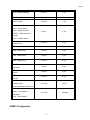
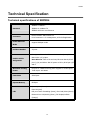
1
SRPM24 24-port Managed PoE Midspan Switch User Manual VER 1.20 Notice The contents of this manual are based on the table below listing firmware version, software kernel version, and hardware version. If the functions are different from the description of contents of manual, please contact the local sale dealer for more information. Firmware Version V1.00 Kernel Version V1.17 Hardware Version A5.00 i SRPM24 FCC Warning This Equipment has been tested and found to comply with the limits for a Class-A digital device, pursuant to Part 15 of the FCC rules. These limits are designed to provide reasonable protection against harmful interference in a residential installation. This equipment generates, uses, and can radiate radio frequency energy. It may cause harmful interference to radio communications if this equipment is not installed and used in accordance with the instructions. However, there is no guarantee that interference will not occur in a particular installation. If this equipment does cause harmful interference to radio or television reception, which can be determined by turning the equipment off and on, the user is encouraged to try to correct the interference by one or more of the following measures: Reorient or relocate the receiving antenna. Increase the separation between the equipment and receiver. Connect the equipment into an outlet on a circuit different from that to which the receiver is connected. Consult the dealer or an experienced radio/TV technician for help. CE Mark Warning This is a Class-A product. In a domestic environment this product may cause radio interference in which case the user may be required to take adequate measures. ii Content FCC Warning ................................................................................................. ii CE Mark Warning ........................................................................................... ii Content ....................................................................................................... iii Introduction.................................................................................................. 5 Features................................................................................................................................6 Software Features ................................................................................................................6 Package Contents .................................................................................................................8 Hardware Description..................................................................................... 9 Physical Dimension...............................................................................................................9 Front Panel ...........................................................................................................................9 LED Indicators ......................................................................................................................9 Rear Panel ..........................................................................................................................10 Power On............................................................................................................................11 Desktop Installation............................................................................................................11 Attaching Rubber Feet........................................................................................................11 Rack-mounted Installation .................................................................................................12 Network Application ...........................................................................................................13 Console Management ................................................................................... 14 Connecting to the Console Port..........................................................................................14 Login in the Console Interface ...........................................................................................15 CLI Management ................................................................................................................16 Commands Level .........................................................................................................................16 Commands Set List......................................................................................................................17 System Commands Set ...............................................................................................................17 SNMP Commands Set..................................................................................................................18 TFTP Commands Set ...................................................................................................................19 SystemLog, SMTP and Event Commands Set..............................................................................19 SNTP Commands Set ..................................................................................................................20 PoE Commands Set .....................................................................................................................20 UPS Commands Set.....................................................................................................................21 Web-Based Management .............................................................................. 22 About Web-based Management .........................................................................................22 iii SRPM24 Preparing for Web Management ........................................................................................22 System Login ......................................................................................................................22 System................................................................................................................................23 System Information.....................................................................................................................23 Console Port Information ............................................................................................................24 System IP Configuration..............................................................................................................24 Security Manager ........................................................................................................................25 System Log .................................................................................................................................26 PoE .....................................................................................................................................27 PoE Status...................................................................................................................................27 Controller Temperature ...............................................................................................................28 PoE Power Manage .....................................................................................................................29 PoE Port Configuration ................................................................................................................30 PoE Port Status ...........................................................................................................................31 MISC Configuration ............................................................................................................31 UPS Status ..................................................................................................................................32 SNTP Configuration .....................................................................................................................33 SNMP Configuration ....................................................................................................................34 Email Alert...................................................................................................................................36 IP Security...................................................................................................................................37 TFTP Firmware Update.......................................................................................................38 Configuration Backup .........................................................................................................39 Save Configuration .............................................................................................................40 Factory Default ...................................................................................................................40 System Reboot ...................................................................................................................40 Troubles shooting ........................................................................................ 43 Incorrect connections .........................................................................................................43 Faulty or loose cables ........................................................................................................43 Non-standard cables ..........................................................................................................43 Improper Network Topologies ...........................................................................................43 Diagnosing LED Indicators .................................................................................................44 Technical Specification ................................................................................. 45 Technical specifications of SRPM24....................................................................................45 iv Introduction Power-over-Ethernet (PoE) eliminates the need to run AC power to other devices on a wired LAN. Using Power-over-Ethernet system installers needs to run only a single Category 5 Ethernet cable that carries both power and data to each device. This allows greater flexibility in the locating of network devices and significantly decreasing installation costs in many cases. There are two system components in PoE -- the PSE (Power Sourcing Equipment) and the PD (Powered Device). The IEEE 802.3af specification defines PSE which inserts power onto an Ethernet cable. The PSE may be located at the device/switch (Endspan configuration), or it may be a separate device located between the device/switch and the PD (Midspan configuration). The PD is the natural termination of this link, receiving the power, and could be an IP phone, a WLAN access point, or any other IP device requires power. The current is transmitted over two of the four twisted pairs of wires in a Category-5 cable. Power over Ethernet follows the IEEE 802.3af and is completely compatible with existing Ethernet devices/switches and networked devices. Because the Power Sourcing Equipment (PSE) tests whether a networked device is PoE-capable, power is never transmitted unless a Powered Device is at other end of the cable. It also continues to monitor the channel. If the Powered Device does not draw a minimum current, because it has been unplugged or physically turned off, the PSE shuts down the power to that port. Optionally, the standard permits Powered Devices to signal to the PSEs exactly how much power they need. 5 SRPM24 Features 24-port PoE Midspan switch with 1 10/100TX for system management 400W Fully Power supported Supports 802.3af pre-standard PD Temperature monitoring Power limit setting TFTP firmware update System log Configuration up-load and down-load SNMP / Web/CLI/Telnet management Circuit short protection Confirms to IEEE802.3 10BASE-T, 802.3u 100BASE-TX and 802.3af Power over Ethernet Supports Redundant Power Simple Network Time Protocol (SNTP) Simple Mail Transfer Protocol (SMTP) DHCP Client supported SNMP Trap supported Management IP address security Fan fail detection Power overloading protection Software Features Management SNMP, Telnet, CLI and Web management. RFC1213 SNMP MIB II, RFC 1628 UPS MIB, RFC2030 RFC Standard SNTP, RFC 2821 SMTP, RFC1215 Trap, RFC 3621 Power over Ethernet, Private MIB, PoE MIB 6 SRPM24 1. Cold start 2. Warm start 3. Authorization fail 4. PD disconnect trap-PoE port event 5. DC disconnect trap-PoE port Event SNMP Trap 6. Disconnect PD off-PoE port event 7. Over loading trap-PoE port event 8. Short circuit trap-PoE port event 9. Over Temp protection trap –PoE port event 10. Power management –PoE port off event * Trap station up to 3 Software Upgrade TFTP firmware upgrade IEEE802.3af PoE System System status display: power voltage, current, power Configuration consumption Temperature and power consumption limitation setup PoE Port Port enable/disable Configuration Power limitation rule configuration Port status Feeding power, current, detected class PoE Port Status Show the cause of port off (AC disconnect off, DC disconnect off, Disconnect PDU off, Over loading off Short circuit off, Over Temp. protection off, Power management — Port off) DHCP IP Management Security Redundant Power Monitor SYSLOG DHCP client Supports 10 IP address accounts for system management security for Web, SNMP, Telnet management security to prevent intruder Input DC voltage, Input DC frequency, Input DC current, Output DC Voltage, Output DC current, and Buzzer control Supports System log record and remote system log server 7 SRPM24 SNTP Supports RFC2030 Simple Network Time Protocol SMTP Up to 4 email recipients Configuration Upload and Download Backup and restore configuration file (via TFTP backup and restore) Package Contents Please refer to the package contents list below to verify them against the checklist. 24-port Managed PoE Midspan switch x 1 User manual x 1 Mounting plate x 2 Module plate x 1 DB9-Male to DB9-Female RS-232 cable x 1 AC Power Cord x 1 Rubber foot x 4 Compare the contents with the standard checklist above. If any item is damaged or missing, please contact the local dealer for service. 8 SRPM24 Hardware Description In this paragraph, the hardware spec, port, cabling information, and wiring installation will be described. Physical Dimension Dimension (W x D x H): 17.3 inch x 11 inch x 1.7 inch 440mm x 280mm x 44mm Front Panel The Front Panel of SRPM24, the 24-port Managed PoE Midspan switch is shown as below, LED Indicators LED Status Color Description On Green Off -- On Orange The connection is operating in full-duplex mode. Blink Green Collision of packets occurs. System power is active PWR FDX/COL Off -- System power is not active The connection is operating in half-duplex mode. 9 SRPM24 On Green Off -- On Green Off -- On Red Off -- On Green Off -- On Green Off -- The Ethernet port is connecting with the device. LINK No device attached. The port is receiving or transmitting data. ACT No data occurred The fan failed. FAN1~FAN4 The fan is working functionally. Power is transmitting to the device Forwarding Power is not transmitting to the device Connected device is overloaded or has shorted. Overload No device attached or power feeding is in good condition. Rear Panel The 3-pronged power plug is located at the rear Panel of the 24-port Managed PoE Midspan switch as shown below. The PoE Midspan switch will work with AC in the range of 100-240Vac, 50-60Hz and also provides one DC 48V input interface for the extra power connection. The RS-232 DB-9 female connector on rear side is used for UPS management. The Rear Panel of SRPM24 10 SRPM24 Power On Connect the power cord to the power socket on the rear panel of the 24-port Managed PoE Midspan switch. Connect the other side of the power cord to the power outlet. The internal power supply of the 24-port Managed PoE Midspan switch works with voltage in the range of 100-240 Vac, frequency 50~60Hz. Check the power indicator on the front panel to see if power is properly supplied. Desktop Installation Set the Device on a sufficiently large flat space with a power outlet nearby. The surface where you put your Device should be clean, smooth, level and sturdy. Make sure there is enough clearance around the Network device to allow attachment of cables, power cord and allow air circulation. Attaching Rubber Feet A. Make sure mounting surface on the bottom of the Network device is grease and dust free. B. Remove adhesive backing from your Rubber Feet. C. Apply the Rubber Feet to each corner on the bottom of the Network device. These footpads can prevent the Network device from shock/vibration. Attaching Rubber Feet to each corner on the bottom of the Device 11 SRPM24 Rack-mounted Installation The switch comes with a rack-mounted kit and can be mounted in an EIA standard size, 19-inch Rack. The Device can be placed in a wiring closet with other equipment. Perform the following steps to rack-mount the device: A. Position one plate to align with the holes on one side of the device and secure it with the smaller plate screws. Then attach the remaining plate to the other side of the Device. Attach mounting plates with screws B. After attaching both mounting plates, position the switch in the rack by lining up the holes in the plates with the appropriate holes on the rack. Secure the Device to the rack with a screwdriver and the rack-mounting screws. Mount the 24-port managed PoE Midspan switch in an EIA standard 19-inch Rack Note: For proper ventilation, allows about at least 4 inches (10 cm) of clearance on the front and 3.4 inches (8 cm) on the back of the Device. This is especially important for enclosed rack installation. 12 SRPM24 Network Application The 24-port Managed PoE Midspan switch can provides power to the PDs that follow the IEEE 802.3af standard in the network. It can solve the problem of position limitation. The network device can be installed in more appropriate position for better performance. The following figures are examples for network application of the Power over Ethernet Device. 24-port Managed PoE Midspan switch network application 13 SRPM24 Console Management Connecting to the Console Port 1. Attach one end of the supplied RS-232 cable to PC or terminal and the other end to the console port of the device. The connected terminal or PC must support the terminal emulation program. 2. Connect one end of an RJ-45 cable to the Ethernet port at the front panel and the other end to PC or terminal for web interface management. The connections among PC, 24-port Managed PoE Midspan switch, UPWM and battery 14 SRPM24 Login in the Console Interface When the connection between the device and PC is ready, turn on the PC and run a terminal emulation program or Hyper Terminal and configure its communication parameters to match the following default characteristics of the console port: Baud Rate: 9600 bps Data Bits: 8 Parity: none Stop Bit: 1 Flow control: None The settings of communication parameters After finishing the parameter settings, click ‘OK’ button. When the blank screen shows up, press Enter key to bring out the login prompt. Key in ‘admin’ (default value) for both User name and Password (use Enter key to switch), then press Enter key and the Main Menu of console management appears. Console login 15 SRPM24 CLI Management The system supports the console management—CLI command. After you log in on to the system, you will see a command prompt. To enter CLI management interface, type in “enable” command (or simply enter “e” and press Enter). Commands Level Modes Access Method Prompt Exit Method About This Mode The user commands available at the user level are a subset of those User EXEC Begin a session with your device. Enter logout SRPM24> or quit. available at the privileged level. Use this mode to • Perform basic tests. • Display system information. The privileged command is Enter the Privileged EXEC the advanced mode. enable command while SRPM24# in User EXEC Enter disable Use this mode to to exit. • Display advanced function status mode. • Save configuration Enter the Global Configuration configure command while in privileged To exit to Use this mode to configure SRPM24 privileged those parameters that are (config)# EXEC mode, going to be applied to your enter exit device. EXEC mode. Enter the poe PoE command while SRPM24 Enter exit to Use this mode to configure Configuration in User EXEC (poe)# exit. PoE parameters. SRPM24 Enter exit to Use this mode to configure (ups)# exit. UPS parameters. mode UPS Configuration Enter the ups command while in User EXEC mode 16 SRPM24 Commands Set List User EXEC D Privileged EXEC E Global configuration C PoE P UPS U System Commands Set Commands Level Description Example show system-info D Shows system information SRPM24>show system-info show version D Shows version information SRPM24>show version show config D Shows device configuration SRPM24>show config show terminal E Shows console information write memory C Save user configuration into SRPM24#write memory SRPM24#show terminal permanent memory (flash rom) write terminal C Displays user configuration SRPM24#write terminal on terminal system name C Configure system name SRPM24(config)#system name xxx C Set device system location SRPM24(config)#system location xxx [System Name] system location string [System Location] system description C Set device system SRPM24(config)#system description xxx description string [System Description] show system-info D Shows system information ip address C Configure the IP address of SRPM24(config)#ip address 192.168.1.1 the device [Ip-address] <space> SRPM24>show system-info 255.255.255.0 192.168.1.254 [Subnet-mask] <space> [Gateway] ip dhcp C of the device [Enable|Disable] reload Enable DHCP client function SRPM24(config)#ip dhcp enable C Reboot the device 17 SRPM24(config)#reload SRPM24 default C Restore to default SRPM24(config)#default username C Change a login SRPM24(config)# username xxxxxx username. [Username] (maximum 10 words) password C SRPM24(config)# password xxxxxx (maximum 10 words) [Password] security enable Specify a password C Enable IP security function SRPM24(config)# ip-security enable C Enable IP security of HTTP SRPM24(config)# ip-security http-server server enable Enable IP security of telnet SRPM24(config)# ip-security telnet-server server enable Set the IP security list SRPM24(config)# ip-security address 1 [Enable|Disable] http-server [Enable|Disable] telnet-server C [Enable|Disable] address C 192.168.1.55 [1~10] [IP] show ip-security E Shows the information of IP SRPM24#show ip-security security SNMP Commands Set Commands snmp system-name Level C [System Name] snmp system-location C [System Location] snmp community-strings C [Community] right Description Example Set SNMP agent SRPM24(config)#snmp system-name system name l2switch Set SNMP agent SRPM24(config)#snmp system-location system location lab Add SNMP community SRPM24(config)#snmp community-strings string. public right rw [RO/RW] snmp-server host C Configure SNMP server host SRPM24(config)#snmp-server host [Host-address] information and community 192.168.1.50 community public trap- community string. version v1 Remove SNMP server host SRPM24(config)#no snmp-server host information. 192.168.1.50 Remove SNMP community SRPM24(config)#no snmp community- [Community-string] no snmp-server host C [Host-address] no snmp community- C 18 SRPM24 strings string. strings public [Community] TFTP Commands Set Commands copy flash:config.text tftp Level C Defaults Description Example Save configuration to TFTP SRPM24(config)# copy flash:config.text and need to specify the IP tftp of TFTP server and the file Ex: Server IP: 192.168.1.20 name of image. tftp:config.text flash C Image Filename: config.text Get configuration from TFTP SRPM24(config)# tftp:config.text flash server and need to specify Ex: Server IP: 192.168.1.20 the IP of TFTP server and Image Filename: config.text the file name of image. tftp:firmware flash C Upgrade firmware by TFTP SRPM24(config)# tftp:firmware flash and need to specify the IP Ex: Server IP: 192.168.1.20 of TFTP server and the file Image Filename: firmware name name of image. SystemLog, SMTP and Event Commands Set Commands Level Description Example Set System log server IP SRPM24(config)# systemlog ip address. 192.168.1.100 C Set System Log Function SRPM24(config)# systemlog enable show systemlog D Display system log. SRPM24>show systemlog show systemlog E Show system log client & SRPM24#show systemlog systemlog ip C [IP address] systemlog [Enable|Disable] server information smtp C Enable SMTP function SRPM24(config)#smtp enable C Configure SMTP server IP SRPM24(config)#smtp serverip [Enable|Disable] smtp ip 192.168.1.5 [IP] smtp auth C Enable SMTP authentication SRPM24(config)#smtp auth enable C Configure authentication [Enable|Disable] smtp account [account] account 19 SRPM24(config)#smtp account User SRPM24 smtp password [password] C Configure authentication SRPM24(config)#smtp password 123456 password smtp recept-mail- C address Set SMTP recept mail SRPM24(config)#smtp recept-mail- address address 1 [email protected] Shows the information of SRPM24#show smtp [1~4] [Mail address] show smtp P SMTP Smtp sender [sender C Set the smtp sender name SRPM24(config)#smtp sender name] SNTP Commands Set Commands Level Description Example sntp enable C Enable SNTP function SRPM24(config)#sntp enable C Set SNTP server IP SRPM24(config)#sntp ip 192.169.1.1 C Set timezone SRPM24(config)#sntp timezone Hawaii [Enable|Disable] sntp ip [IP] sntp timezone [Country] PoE Commands Set Commands Level Description Example poe P Enable PoE function. SRPM24#poe portebl P Port Enable & Disable SRPM24(poe)#portebl enable 2 configure. [Enable|Disable] [Ports] portplm P P P [Enable|Disable] temperature-alarm [1~2] [Temperature (0- Set system power limit SRPM24(poe)#system-power-limit 200 value. [37~400] 8023af-pre-standard SRPM24(poe)#portplm 15400 3 Setting. [100~15400] [Port] system-power-limit Port Power Limit Max P Set IEEE 802.3af pre- SRPM24(poe)#8023af-pre-standard standard. enable Set system temperature SRPM24(poe)#temperature-alarm 1 50 alarm. 150C)] 20 SRPM24 power-management P Set power management SRPM24(poe)#power-management 5 mode. [1~5] show status P Shows PoE status. SRPM24(poe)#show status show configure P Shows PoE configuration SRPM24(poe)#show configure show system P Shows PoE system SRPM24(poe)#show system information. show temperature P Shows PoE system SRPM24(poe)#show temperature temperature. show power- P Shows PoE power SRPM24(poe)#show power-management management mode. management UPS Commands Set Commands Level Description Example status U Show ups status SRPM24(ups)#status info U Show ups info SRPM24(ups)#info test10 U Test ups for 10 seconds SRPM24(ups)#test10 21 SRPM24 Web-Based Management This section introduces the configuration and functions of the Web-Based management. About Web-based Management There is an embedded HTML web site residing in flash memory on CPU board of the device, which offers advanced management features and allows users to manage the device from anywhere on the network through a standard browser such as Microsoft Internet Explorer. The Web-Based Management supports Internet Explorer 6.0 or later version. And, it is applied for Java Applets for reducing network bandwidth consumption, enhance access speed and present an easy viewing screen. Preparing for Web Management Before using the web management, install the managed PoE Midspan switch on the network and make sure that any one of the PCs on the network can connect with the managed PoE Midspan switch through its Ethernet port. The default value of IP, subnet mask, username and password for the managed PoE Midspan switch are listed as below: IP Address: 192.168.16.1 Subnet Mask: 255.255.255.0 Default Gateway: 192.168.16.254 User Name: admin Password: admin System Login 1. Launch the Internet Explorer on the PC 2. Key in “http:// “+” the IP address of the device”, and then Press “Enter”. 22 SRPM24 3. The login screen will appear right after 4. Key in the user name and password. The default user name and password are the same as ‘admin 5. Press ‘Enter‘ or click OK button, and then the home screen of the Web-based management appears. System The article of PoE contains 5 sub-items, such as follows: ¾ System Information ¾ Console Port Information ¾ System IP Configuration ¾ Security Manager ¾ System Log System Information The System Information page displays the summary information of the Device. 23 SRPM24 System Name: Displays the system name of the managed PoE Midspan switch. System Description: Describes the managed PoE Midspan switch. System Location: Displays the device physical location. Firmware Version: Displays the firmware version of the device. Kernel Version: Displays the kernel software version. Hardware Version: Displays the hardware version. MAC Address: Displays the unique hardware address assigned by manufacturer. PoE Chip Version: Displays the PoE chip version on main board. System information Console Port Information Baud Rate(bps): Displays the transmission rate (bits per second). Parity Check: Displays which parity check method is used. Data Bits(bit): Displays the number of bits per unit of data. Stop Bits(bit): Displays the number of bits for announcing the end of the data. Flow Control: Displays the method of flow control. Console Port Information System IP Configuration 24 SRPM24 User can configure the IP Settings and DHCP client function in here. DHCP Client: Enable or disable the DHCP client function. When DHCP client function is enabled, the managed PoE Midspan switch will be assigned an IP address from the network DHCP server. The default IP address will be replaced by the assigned IP address on DHCP server. After the user click Apply button, a popup dialog shows up to inform the user that when the DHCP client is enabled, the current IP will lose and the user should find the new IP on the DHCP server. IP Address: Assign the IP address that the network is using. If DHCP client function is enabled, the user doesn’t need to assign the IP address. And, the network DHCP server will assign the IP address displaying in this column for the PoE Midspan switch. The default IP is 192.168.16.1. Subnet Mask: Assign the subnet mask to the IP address. If DHCP client function is enabled, the user does not need to assign the subnet mask. Gateway: Assign the network gateway for the PoE Midspan switch. The default gateway is 192.168.16.254. And then, click Apply IP configuration Security Manager Change login user name and password for management security. User Name: Type in the new user name (The default value is “admin”). New Password: Type in the new password (The default value is “admin”). Confirm Password: Re-type the new password. And then, click Apply button to make the configuration effective. 25 SRPM24 Security Manager System Log Configure the system event mode to collect system log. System Log Client Mode: Select the system log mode—Disable or Enable. System Log Server IP Address: Assign the system log server IP. When System Log Client Mode is set as Disable, the system event log will only be reserved in the RAM of the PoE Midspan switch until next reboot. When System Log Client Mode is set as Enable, the system log will be reserved in the RAM of the PoE Midspan switch and sent to the system log server. Click Refresh to refresh the events log. Click to clear all current events log. After configuring, click Clear Apply . 26 SRPM24 System Log PoE The article of PoE contains 5 sub-items, such as follows: ¾ PoE Status ¾ Controller Temperature ¾ PoE Power Manage ¾ PoE Port Configuration ¾ PoE Port Status PoE Status Current Get Power: Displays the current get power (watts). Currently Power Consumption: Displays the currently power consumption. Currently Voltage: Displays the currently operating voltage. 27 SRPM24 Current: Displays the loading current (ampere). System Power Limit: Key in the system power limit. IEEE 802.3af Pre-standard: Enable or disable IEEE 802.3af Pre-standard function. When it’s disabled, the legacy powered devices will not be powered. Click Refresh for getting newest status, and then click Apply to have the configuration taken effective. PoE Status Controller Temperature Controller Temperature Chipset & Port number: Displays the controller chip number or the group of ports. Current Temperature: Displays the current operating temperature of the chip. Set Temperature Alarm: Set the number of temperature in centigrade. When the operating temperature of the chip reaches this set number, the Status column next to it will show an alarm message. 28 SRPM24 Click And then, click Refresh to refresh the current state information. Apply PoE Power Manage PoE Power Manage Total Allocated Power: Displays the total allocated power of the device. Port Power Limit: Displays the power limit to a single port. Start Condition: Displays the type of start condition. Power Management Mode: There are 5 modes for selecting. Please refer to the table below or click the Help And then, click button to view the help window. Apply Power Management Mode Management Mode: Dynamic - based on actual power used (mode 1). Static - preset by user (mode 2 & 3) Class - set classification by PD, also according to IEEE 802.3af (mode 4 & 5). Total Allocated Power: 29 SRPM24 Consumption - sum of power consumed by all ports. Class - sum of all ports power according to their class, except for class 0 & 4 for which the actual power consumption is summed. Port Power Limit: Predefined - user defined limit by port power limit. Class - if PD’s power exceeds power according to its class. Max - full power according to 802.3af (15.4W, 44V) Start Condition: N/A Class - no special condition - start port only, if its maximum allowed power according to its class is higher than the user defined power limit; except for classes 0-4 for which no start condition exists. [Note] PD class 1 power is 4w, PD class 2 power is 7w, PD class 0, 3, 4 power is 15.4w. PoE Port Configuration PoE Port Configuration Port: Port 1 ~ port 24 are listed in this column for selecting. Port State: Enable or disable the port being selected in the left column. Power Limit Value: Set the power limit value to the port. And then, click Apply 30 SRPM24 PoE Port Status Port: Displays the port number. Status: Displays the status of the port. Forward Power: Displays the forwarding power which is provided by the device. Current: Displays the current of the port. Class: Displays the class number. Event: Displays the related events to the port. And then, click Refresh to get the newest information. PoE Port Status MISC Configuration The article of MISC Configuration contains 5 sub-items: ¾ UPS Status ¾ SNTP Configuration ¾ SNMP Configuration 31 SRPM24 ¾ Email Alert ¾ IP Security UPS Status Power Status Input Voltage: Displays the real, minimum, and maximum input voltage. Output Voltage: Displays the real, minimum, and maximum output voltage. Frequency: Displays the real, minimum, and maximum frequency. Battery Capacity: Displays the real, minimum, and maximum battery capacity. UPS Load Status: Displays the real, minimum, and maximum UPS load status. Temperature: Displays the real, minimum, and maximum operating temperature. RatVoltage(Vac): Displays the Rat Voltage(Vac). RatVoltage(Vdc): Displays the Rat Voltage(Vdc). RatCurrent: Displays the RatCurrent. RatFrequence: Displays the RatFrequence. Click Refresh button to get the newest information. 32 SRPM24 SNTP Configuration User can configure the SNTP (Simple Network Time Protocol) settings. The SNTP allows user to synchronize device clocks in the Internet. SNTP Configuration SNTP Client: Enable or disable SNTP function to get the time from the SNTP server. UTC Timezone: Set the device location time zone. The following table lists the different location time zone for your reference. SNTP Server IP: Set the SNTP server IP address. Switch Timer: Displays the device current time. Local Time Zone Conversion from UTC Time at 12:00 UTC November Time Zone - 1 hour 11am Oscar Time Zone -2 hours 10 am ADT - Atlantic Daylight -3 hours 9 am -4 hours 8 am -5 hours 7 am -6 hours 6 am -7 hours 5 am -8 hours 4 am AST - Atlantic Standard EDT - Eastern Daylight EST - Eastern Standard CDT - Central Daylight CST - Central Standard MDT - Mountain Daylight MST - Mountain Standard PDT - Pacific Daylight PST - Pacific Standard ADT - Alaskan Daylight 33 SRPM24 ALA - Alaskan Standard -9 hours 3 am HAW - Hawaiian Standard -10 hours 2 am Nome, Alaska -11 hours 1 am +1 hour 1 pm +2 hours 2 pm BT - Baghdad, USSR Zone 2 +3 hours 3 pm ZP4 - USSR Zone 3 +4 hours 4 pm ZP5 - USSR Zone 4 +5 hours 5 pm ZP6 - USSR Zone 5 +6 hours 6 pm +7 hours 7 pm +8 hours 8 pm +9 hours 9 pm +10 hours 10 pm +12 hours Midnight CET - Central European FWT - French Winter MET - Middle European MEWT - Middle European Winter SWT - Swedish Winter EET - Eastern European, USSR Zone 1 WAST - West Australian Standard CCT - China Coast, USSR Zone 7 JST - Japan Standard, USSR Zone 8 EAST - East Australian Standard GST Guam Standard, USSR Zone 9 IDLE - International Date Line NZST - New Zealand Standard NZT - New Zealand SNMP Configuration 34 SRPM24 Use this page to define management stations as trap managers and to enter SNMP community strings. You can also define a name, location and contact person for the device. SNMP configuration Here you can define the new community string set and remove the unwanted community string. System Option: Name: Fill in a string for identifying. Location: Fill in a string to describe where the Device is. Contact: Fill in a string to describe the contact personnel. Click Apply button. Community Strings: String: Fill in a new community string which serve as passwords and can be entered as RO or RW type. RO: Read only. Enables requests accompanied by this community string to display MIB-object information. 35 SRPM24 RW: Read write. Enables requests accompanied by this community string to display MIB-object information and to set MIB objects. button. Click Add To remove the community string, select the community string that you have defined and click Remove button. You cannot edit the name of the default community string set. Trap Manager: A trap manager is a management station that receives the trap messages generated by the Device. If no trap manager is defined, no traps will be issued. Create a trap manager by entering the IP address of the station and a community string. To define a management station as a trap manager, assign an IP address, enter the SNMP community strings, and select the SNMP trap version. IP Address: Enter the IP address of the trap manager. Community: Enter the community string. Trap Version: Select the SNMP trap version type—v1 or v2c. Click Add To remove the community string, select the community string listed in the current managers field and click button. Remove button. There are three types of trap: Standard: Includes DHCP Setting, Authentication Failure, and Cold Start. Power over Ethernet: Includes DC disconnect, PD disconnect, Overload, Short Circuit, Over Temperature, Port off by Power Management. UPS: Includes Power Disconnect, Power Fault, Battery Low, and Power Over Temperature. [Note] Power over Ethernet traps also record in System Log and E-mail Alert. Email Alert You can set up the mail server IP, mail account, password, and forwarded email account for receiving the event alert. Email Alert: Enable or disable the email alert function. SMTP Server IP: Assign the mail server IP address (when Email Alert enabled, this function will then be available). Sender: Type in an alias of the device in complete email address format, e.g. [email protected], to identify where the event log comes from. 36 SRPM24 Authentication: Tick the checkbox to enable this function, configuring the email account and password for authentication (when Email Alert enabled, this function will then be available). Mail Account: Set up the email account, e.g. [email protected], to receive the alert, please use valid email account on the mail server. Password: Enter the password to the email account. Confirm Password: Reconfirm the password. Rcpt e-mail Address 1 ~ 4: You can also assign up to 4 e-mail accounts to receive the alert. Click Apply button. Email Alert IP Security IP security function allows the user to assign 10 specific IP addresses that have permission to access the device through the web browser and telnet for the security management. Enable IP Security: When this option is in Enable mode, the Enable HTTP Server and Enable Telnet Server functions will then be available. Enable HTTP Server: When this checkbox is ticked, the IP addresses among Security IP1 ~ IP10 will be allowed to access this device via HTTP service. Enable Telnet Server: When this checkbox is ticked, the IP addresses among Security IP1 ~ IP10 will be allowed to access this device via telnet service. Security IP 1 ~ 10: The system allows the user to assign up to 10 specific IP addresses for access 37 SRPM24 security. Only these 10 IP addresses can access and manage the device through the HTTP/Telnet service. And then, click [NOTE] Apply button to apply the configuration. The SNTP and SMTP server IP address also need to be in the list. Remember to execute the “Save Configuration” action, otherwise the new configuration will lose when the device powers off. IP Security TFTP Firmware Update It provides the functions that allow user to update the device firmware. Before updating, make sure the TFTP server is ready and the firmware image is located on the TFTP server. 38 SRPM24 Update Firmware TFTP Server IP Address: Type in your TFTP server IP. Firmware File Name: Type in the name of the firmware image file. Click Apply button to start upgrading firmware for the PoE Midspan switch. Configuration Backup You can backup the current configuration from flash ROM to TFTP server or restore the old configuration from TFTP server. TFTP Server IP Address: Type in the TFTP server IP. Backup File Name: Type in the file name for backup. Restore File Name: Type in the file name for restoring. Click Apply . Backup/Restore Configuration 39 SRPM24 Save Configuration Save Configuration is used to save the user configuration to permanent data. If users want to keep their configuration after rebooting, they must save configuration. Save Configuration Factory Default Reset the device to the factory defaults. Click Default button to reset all configurations to the default value. Factory default reset button System Reboot Reboot the device in software reset. Click Reboot 40 button to reboot the system. SRPM24 System reboot 41 SRPM24 42 SRPM24 Troubles shooting Incorrect connections To link the Managed PoE Midspan switch with other Ethernet device, you should use correct UTP/STP cable. The link will fail if the RJ-45 connector is not correctly pinned on right position. Faulty or loose cables Look for loose or obviously faulty connections. If they appear to be OK, make sure the connections are snug. IF that does not correct the problem, try a different cable. Non-standard cables Non-standard and miss-wired cables may cause numerous network collisions and other network problem, and can seriously impair network performance. A category 5-cable tester is a recommended tool for network installation. Use unshielded twisted-pair (UTP) or shielded twisted-pair (STP) cable for RJ-45 connections. Also be sure that the length of any twisted-pair connection does not exceed 100 meters (328 feet). Improper Network Topologies It is important to make sure that you have a valid network topology. Common topology faults include excessive cable length and too many repeaters (devices) between end nodes. In addition, you should make sure that your network topology contains no data path loops. Between any two end nodes, there should be only one active cabling path at any time. Data path loops will cause broadcast storms that will severely impact your network performance. 43 SRPM24 Diagnosing LED Indicators To assist in identifying problems, the device can be easily monitored through panel indicators, which describe common problems the user may encounter and where the user can find possible solutions. IF the power indicator does not light on when the power cord is plugged in, you may have a problem with power outlet, or power cord. However, if the device powers off after running for a while check for loose power connections, power losses or surges at power outlet. If you still cannot resolve the problem, contact your local dealer for assistance. 44 SRPM24 Technical Specification Technical specifications of SRPM24 IEEE802.3 10Base-T Standard IEEE802.3u 100Base-TX IEEE802.3af Power over Ethernet Connector Power Ethernet Mode PoE Port Number RS-232 console: DB-9 Female x 2 RJ-45 connector: 1 for management, 48 for PoE application Support Mid-Span mode 24 ports Data port: links to the Ethernet device and only carry Ethernet POE RJ-45 Pin Assignment data on the 1,2,3,6 pins. Data & Power: links to PD and carry Ethernet data by RJ-45 pin 1,2,3,6, and deliver 48V DC power to PD by RJ-45 pin 4,5,7 and 8 Maximum Feeding Per port 15.4 Watts and fully power support for 24 PoE ports. Power Total output: 400 Watts Flash ROM 512K Bytes System Memory 8M Bytes System power (Green) FAN: Fail (Red) LED PoE port: Power forwarding (Green), Over load /Short (Green) Ethernet Port: Link/Activity (Green), Full Duplex/Collision (Orange) 45 SRPM24 400W switch power supply embedded. Power AC input 100~240V 50/60Hz, A (Maximum) DC input 48V Power Consumption 407 Watts (Maximum) @AC 110V Ventilation 4 Fans with fault detecting function Operating Environment Storage Environment 0oC~45oC, 5%~95%RH -40oC ~70oC, 95% RH Case Dimension 17.3 inch x 11inch x 1.7 inch (WxDxH) 440 mm x 280 mm x 44 mm EMI FCC Class A CE UL Safety cUL CE/EN60950-1 46 SRPM24 ©Amer.com Corp. 1997-2007 All rights reserved. 47