1
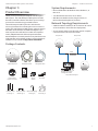
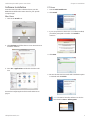
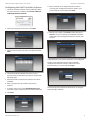
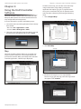
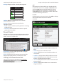
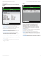
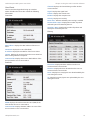
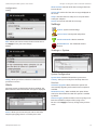
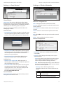
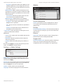
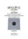
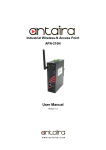
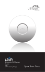
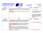
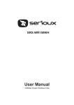
Enterprise WiFi System
UniFi Enterprise WiFi System User Guide
Table of Contents
Table of Contents
Chapter 1:
Product Overview . . . . . . . . . . . . . . . . . . . . . . . . . . . . . . . . . . . . . . . . . . . . . . . . . . . 1
Package Contents. . . . . . . . . . . . . . . . . . . . . . . . . . . . . . . . . . . . . . . . . . . . . . . . . . . . . . . . . . . . . . . . 1
System Requirements . . . . . . . . . . . . . . . . . . . . . . . . . . . . . . . . . . . . . . . . . . . . . . . . . . . . . . . . . . . . 1
Network Topology Requirements. . . . . . . . . . . . . . . . . . . . . . . . . . . . . . . . . . . . . . . . . . . . . . . . . 1
Front. . . . . . . . . . . . . . . . . . . . . . . . . . . . . . . . . . . . . . . . . . . . . . . . . . . . . . . . . . . . . . . . . . . . . . . . . . . . . 2
Back . . . . . . . . . . . . . . . . . . . . . . . . . . . . . . . . . . . . . . . . . . . . . . . . . . . . . . . . . . . . . . . . . . . . . . . . . . . . . 2
Chapter 2:
Installation . . . . . . . . . . . . . . . . . . . . . . . . . . . . . . . . . . . . . . . . . . . . . . . . . . . . . . . . . . 3
Hardware Installation. . . . . . . . . . . . . . . . . . . . . . . . . . . . . . . . . . . . . . . . . . . . . . . . . . . . . . . . . . . . . 3
Software Installation. . . . . . . . . . . . . . . . . . . . . . . . . . . . . . . . . . . . . . . . . . . . . . . . . . . . . . . . . . . . . . 5
Chapter 3:
Using the UniFi Controller Software . . . . . . . . . . . . . . . . . . . . . . . . . . . . . . . . . . 7
Map. . . . . . . . . . . . . . . . . . . . . . . . . . . . . . . . . . . . . . . . . . . . . . . . . . . . . . . . . . . . . . . . . . . . . . . . . . . . . . 7
Statistics . . . . . . . . . . . . . . . . . . . . . . . . . . . . . . . . . . . . . . . . . . . . . . . . . . . . . . . . . . . . . . . . . . . . . . . . . 9
Access Points. . . . . . . . . . . . . . . . . . . . . . . . . . . . . . . . . . . . . . . . . . . . . . . . . . . . . . . . . . . . . . . . . . . . . 9
Users. . . . . . . . . . . . . . . . . . . . . . . . . . . . . . . . . . . . . . . . . . . . . . . . . . . . . . . . . . . . . . . . . . . . . . . . . . . . 10
Guests . . . . . . . . . . . . . . . . . . . . . . . . . . . . . . . . . . . . . . . . . . . . . . . . . . . . . . . . . . . . . . . . . . . . . . . . . . 10
Recent Events. . . . . . . . . . . . . . . . . . . . . . . . . . . . . . . . . . . . . . . . . . . . . . . . . . . . . . . . . . . . . . . . . . . 11
Alerts . . . . . . . . . . . . . . . . . . . . . . . . . . . . . . . . . . . . . . . . . . . . . . . . . . . . . . . . . . . . . . . . . . . . . . . . . . . 15
Settings. . . . . . . . . . . . . . . . . . . . . . . . . . . . . . . . . . . . . . . . . . . . . . . . . . . . . . . . . . . . . . . . . . . . . . . . . 15
Admin . . . . . . . . . . . . . . . . . . . . . . . . . . . . . . . . . . . . . . . . . . . . . . . . . . . . . . . . . . . . . . . . . . . . . . . . . . 17
Appendix A:
Specifications. . . . . . . . . . . . . . . . . . . . . . . . . . . . . . . . . . . . . . . . . . . . . . . . . . . . . . . 18
Appendix B:
Compliance Information. . . . . . . . . . . . . . . . . . . . . . . . . . . . . . . . . . . . . . . . . . . . 19
FCC. . . . . . . . . . . . . . . . . . . . . . . . . . . . . . . . . . . . . . . . . . . . . . . . . . . . . . . . . . . . . . . . . . . . . . . . . . . . . 19
Industry Canada. . . . . . . . . . . . . . . . . . . . . . . . . . . . . . . . . . . . . . . . . . . . . . . . . . . . . . . . . . . . . . . . . 19
Appendix C:
Warranty . . . . . . . . . . . . . . . . . . . . . . . . . . . . . . . . . . . . . . . . . . . . . . . . . . . . . . . . . . . 20
General Warranty. . . . . . . . . . . . . . . . . . . . . . . . . . . . . . . . . . . . . . . . . . . . . . . . . . . . . . . . . . . . . . . . 20
Appendix D:
Contact Information. . . . . . . . . . . . . . . . . . . . . . . . . . . . . . . . . . . . . . . . . . . . . . . . 21
Ubiquiti Networks Support. . . . . . . . . . . . . . . . . . . . . . . . . . . . . . . . . . . . . . . . . . . . . . . . . . . . . . 21
Ubiquiti Networks, Inc.
i
UniFi Enterprise WiFi System User Guide
Chapter 1: Product Overview
Chapter 1:
Product Overview
System Requirements
Thank you for purchasing the Ubiquiti UniFi Enterprise
WiFi System. The UniFi Enterprise WiFi System includes
the UniFi Controller software that allows you to manage
your wireless network using your Web browser.
• Java Runtime Environment 1.6 (or above)
• Microsoft Windows XP, Windows Vista, Windows 7, or
Mac OS X
The UniFi Enterprise WiFi System also includes the
necessary hardware for mounting the unit on a wall or a
ceiling. The UniFi Enterprise WiFi System supports Passive
PoE which works with the included PoE adapter. If you
want to power the UniFi AP from an 802.3af compliant
switch, Ubiquiti Networks offers the optional Instant
802.3af Adapter to instantly transform any PoE device into
a fully 48V 802.3af compliant product. Product details are
available on our website at http://ubnt.com/8023af
• Web Browser: Mozilla Firefox, Google Chrome, or
Microsoft Internet Explorer 8 (or above)
Network Topology Requirements
• A DHCP-enabled network (for AP to obtain an IP as well
as for the wireless clients after the deployment)
• Access point(s) and the management station computer
connected to the same layer-2 network.
Enterprise AP
Enterprise AP
Package Contents
Switch
Wall Mount
UniFi Enterprise AP
Wall-Mount Bracket
Ceiling-Mount Plate
Computer to be used as
Management Station
Enterprise AP
Sample Network Diagram
UniFi Controller
CD with User Guide
M3X30 Flat Head
Screw (Qty. 3)
Quick Start Guide
M3 Nut with Tooth
Washer (Qty. 3)
Ubiquiti Networks, Inc.
24v PoE
Adapter
M2.9x20 Self Tapping
Screw (Qty. 3)
Power Cord
M3x20 Screw
Anchor (Qty. 3)
1
UniFi Enterprise WiFi System User Guide
Front
Chapter 1: Product Overview
Back
Reset Button The reset button serves two functions:
• Restart It will restart the device when you press
and release it quickly.
• Restore Factory Defaults When you press and
hold it for more then 5 seconds, it will restore the
device to the factory default settings.
LED Indicates the status of the device. See
the table below for details.
LED Color
Status
Flashing Amber
Initializing
Steady Amber
Factory default, waiting to be integrated
Alternating
Amber/Green
Device is busy, do not touch or unplug it,
this usually indicates a process such as a
firmware upgrade is taking place
Ethernet Port Connects to the 24v PoE
Adapter to provide power to the unit.
Quickly Flashing This is used to locate an AP.
Green
When you click on Locate in the UniFi
Controller software, the AP will blink. It will
also display the location of the AP on the
map.
Steady Green
Indicates the device has been successfully
integrated into a network and is working
properly
Ubiquiti Networks, Inc.
2
UniFi Enterprise WiFi System User Guide
Chapter 2:
Installation
Chapter 2: Installation
Below is an overview of the Power over Ethernet
connections.
Hardware Installation
The UniFi Enterprise AP is powered by the included PoE
(Power over Ethernet) adapter. To install the AP, perform
the following steps:
1. Connect an Ethernet cable to the Ethernet port on the
UniFi Enterprise AP.
Power Connection Diagram
Mounting the Access Point
The UniFi Enterprise AP can be wall-mounted or
mounted on a ceiling. Perform the following steps for the
appropriate installation:
Wall-Mount
2. Connect the power cord to the power port on the PoE
Adapter. Connect the other end to of the power cord to
a power outlet.
1. Align the wall-mounting bracket with the Wall Mount
text facing up. There are horizontal and vertical lines on
the bracket to help with orientation.
Wall Mount text
Wall Mount
2. Use a pencil to mark the holes on the wall.
3. Use a 6 mm drill bit to drill the holes in the wall.
4. Insert the 3 screw anchors into the wall.
3. Connect the other end of the Ethernet cable to the
Ethernet port labeled POE on the PoE Adapter.
5. Secure the wall-mount bracket to the wall by inserting
the self tapping screws into the anchors.
Note: If you plan to mount the AP on your ceiling,
perform the ceiling mount installation steps before
connecting the Ethernet cable to the PoE Adapter.
Wall Mount
Ubiquiti Networks, Inc.
3
UniFi Enterprise WiFi System User Guide
Chapter 2: Installation
6. Align the notches on the AP with the notches on the
wall‑mount bracket.
Wall Mount
7. Turn the AP clockwise until it locks into place.
6. Feed the Ethernet cable through the hole and then
align the Enterprise AP with the notches on the wallmount bracket.
Wall Mount
Ceiling-Mount
1. Remove the ceiling tile.
2. Align the ceiling-mount plate to the center of the top
side of the ceiling tile.
3. Use a 3.5 mm drill bit to drill holes for the three flat
head screws.
4. Cut or drill a circle approximately 25 mm in size that
lines up with the larger circle on the ceiling-mount
plate. This will be used for the Ethernet cabling.
5. Secure the wall-mount bracket and ceiling-mount plate
to the ceiling tile using the 3 flathead screws and 3 nuts
with tooth washers.
Note: The UniFi AP supports Passive PoE which
works with the included PoE adapter. If you want
to power the UniFi AP from an 802.3af compliant
switch, Ubiquiti Networks offers the optional
Instant 802.3af Adapter to instantly transform
any PoE device into a fully 48V 802.3af compliant
product. Product details are available on our
website at http://ubnt.com/8023af
7. Turn the AP clockwise until it locks into place.
Ubiquiti Networks, Inc.
4
UniFi Enterprise WiFi System User Guide
Chapter 2: Installation
Software Installation
PC Users
Insert the UniFi Controller software CD into your CDROM drive and follow the instructions for your specific
computer type.
1. Launch UniFi-installer.exe.
2. Click Install.
Mac Users
1. Click on the Install icon.
3. If your computer doesn’t have Java 1.6 or above installed,
you will be prompted to install it. Click Install to
continue.
2. Click Continue and follow the on-screen instructions to
install the software.
4. Click Next.
3. Go to Go > Applications and double-click the UniFi
icon.
5. Be sure the Start UniFi Controller after installation option
is checked and click Finish.
Proceed to Configuring the UniFi Controller Software on
page 6.
Note: The UniFi Controller software can also be
launched from Start > All Programs.
Ubiquiti Networks, Inc.
5
UniFi Enterprise WiFi System User Guide
Configuring the UniFi Controller Software
1. The UniFi Controller software startup will begin. When
the option becomes available, click Launch a Browser
to Manage Wireless Network.
Chapter 2: Installation
5. Enter an admin name and password to use when
accessing the management interface. Confirm your
password in the Confirm field. Click Next.
2. Select your language and country. Click Next.
6. Review your settings. Click Back to make changes or
Finish to save your settings. Once finished you will be
redirected to the management interface via your web
browser.
3. Select the devices that you want to configure and click
Next.
Congratulations, your wireless network is now configured.
A login screen will appear for the UniFi Controller
management interface. Enter the admin name and
password that you created and click Login.
4. The UniFi Installation Wizard will create a secure
primary wireless network for your devices. Perform the
following steps:
a. Enter the wireless network name (SSID) in the Secure
SSID field.
b. Enter a passphrase to be used for your primary
network.
c. To enable guest access, select Enable Guest Access
and enter a guest network name in the Guest SSID field.
Proceed to the next chapter for information on using the
UniFi Controller software.
d. Click Next.
Ubiquiti Networks, Inc.
6
UniFi Enterprise WiFi System User Guide
Chapter 3:
Using the UniFi Controller
Software
The UniFi Controller software that comes with your UniFi
Enterprise WiFi System has a browser-based interface for
easy configuration and management.
Chapter 3: Using the UniFi Controller Software
To add a custom map, you must first create the image
using an illustration, image editing, or blueprint
application that exports .jpg, .gif, or .png file formats.
Once you’ve created the map, you can upload it to the
UniFi Controller software by performing the following
steps:
1. Click Configure Maps.
Configure Maps button
To access the interface, perform the following steps:
1. Launch the UniFi Controller application if hasn’t already
been started.
• Mac users: Go > Applications > UniFi
• PC users: Start > All Programs > UniFi
2. The login screen will appear. Enter the admin name and
password in the appropriate fields and click Login.
2. Click Add a Map.
Add a Map
Map
The UniFi Controller software allows you to upload map
images of your location(s) for a visual representation of
your wireless network. When you initially launch the UniFi
Controller application, a default map is displayed.
3. Browse for an image to use as a map (valid file
formats are .jpg, .gif, and .png). Give the image a brief
description. Click Continue.
Ubiquiti Networks, Inc.
7
UniFi Enterprise WiFi System User Guide
4. Click Close.
Chapter 3: Using the UniFi Controller Software
Lock Locks the selected Access Point in the
current location on the map.
Details Brings up the Details window. This
allows you to view Access Point settings and
connected users. You can also edit the radio
channel, transmit power, and device alias.
5. You can adjust the zoom using the slider on the right.
Drag the Access Point icon(s) from the Unplaced APs
list on the left to the appropriate location(s) on the map.
There are 4 tabs to select from in the
Details window. Details, Users, Guests, and
Configuration.
• Details Displays details on the Access Point
including the MAC address, model, version,
IP address, uptime, connected users, and
connected guests. Click Radio to display the
channel used, transmit power, and packet
information.
• Users Displays the hostname of the users
that are connected to the selected Access
Point and the IP address assigned to them.
The access point will appear in the area that you placed it.
You can click on the hostname to display
additional details of each user. A window
with Details, Statistics, and Configuration is
displayed. The Details tab displays the MAC
address, hostname, IP address, uptime and
the AP they are connected to. The Statistics
tab displays the channel used, signal strength,
transmit and receive rates, power saving
enabled or disabled, and the number of
packets sent and received. You can also click
History to see a sortable list of events. The
Configuration tab allows you to change the
alias name for the device.
• Guests Displays the MAC address of guests
that are connected to the guest network.
• Configuration Allows you to change the
alias name of the device, the channel setting,
and set the transmit power to Auto, High,
Medium, or Low. You can also remove the AP
if you no longer want to manage it with the
UniFi software.
Access Point Shows the location of the Access
Point on the map.
Remove Remove the Access Point from the
location on the map.
Click and hold this icon to drag the Access Point
to another location on the map.
Click on the Access Point icon to reveal
additional options. Click a blank area of the map
to hide the additional options.
Ubiquiti Networks, Inc.
8
UniFi Enterprise WiFi System User Guide
Show: You can select to show labels or details and
wireless coverage on the map. The following are the
options available:
• Labels Displays the name of the Access Point.
Chapter 3: Using the UniFi Controller Software
3. Enter the distance that the line represents in the
Distance: field. The distance is specified in meters by
default but you can switch to feet using the drop-down
selection menu on the right. Click Next.
• Details Displays the Access Point name, MAC address,
transmit/receive channel, number of users connected,
and number of guests connected.
• Coverage Displays a visual representation of the range
covered by the Access Point.
Map: If multiple maps have been uploaded, you can
select which map you want to view using this option.
Configure Maps Use this option to add maps or edit the
current map(s).
Zoom Slider Use to zoom the map detail in and out.
Statistics
The Statistics tab provides a visual representation of the
network traffic connected to your managed APs. Charts
representing the number of clients and network traffic are
displayed. An hour by hour chart of the usage over the last
24 hours is also displayed on this screen.
Set Map Scale Use this option to define the scale of the
map. You will draw a line and define the distance that the
line represents.
Setting the Map Scale
1. Click the Set Map Scale button.
2. Click and hold to draw a line in the area that you want
to use to set the scale of the map. If you need to redraw
the line, just click and hold again to draw a new line.
Once you’re happy with the line, click Next.
Access Points
The Access Points tab displays a list of managed Access
Points with their name, IP address, status, number of
clients connected, download/upload statistics, and their
transmit/receive channel.
Search Allows you to search the tables for any
information that is displayed.
Ubiquiti Networks, Inc.
9
UniFi Enterprise WiFi System User Guide
Name/Mac Address Displays the hostname, alias, or MAC
address of the Access Point. You can click on the name to
get additional details on the Access Point.
Chapter 3: Using the UniFi Controller Software
Activity Displays the level of activity for each user.
Bars
IP Address Displays the IP address of the Access Point.
Activity Level
(Bytes per second)
Idle
Status Displays the connection status information.
500
Num Clients Displays the number of clients connected to
the Access Point.
8000
Download Displays the total size of downloads via the
Access Point.
64000
Upload Displays the total size of uploads via the Access
Point.
2048000
Channel Displays the transmit/receive channel being
used by the Access Point.
Actions Select an action button to perform the desired
action:
• Restart Restart the selected Access Point.
• Locate Locate the Access Point on the map. The LED on
unplaced APs will flash to indicate which AP it is so that
you can place it in the correct location on the map.
• Upgrade When Automatic Upgrade is enabled,
the Access Points will be automatically upgraded.
The Upgrade option is used to manually update the
firmware on the Access Point.
512000
Uptime Displays the total time the user has been
connected for this session.
Actions Click an action button to perform the
appropriate action.
• Block Click this to block a specific user from accessing
the Access Point. This will add the client to the Blocked
Device list.
• Reconnect Click this button to reconnect a specific user
to the Access Point.
Guests
The Guests tab displays a list of users that have connected
to the guest network of the Access Point.
Users
The Users tab displays a list of users that are connected to
the primary wireless network of the Access Point.
Name/MAC Address Displays the hostname, alias, or
MAC address of the connected guest. You can click on the
name to get additional details.
Name/MAC Address Displays the hostname, alias, or MAC
address of the connected user. You can click on the name
to get additional details.
IP Address Displays the IP address assigned to the user.
Access Point Displays the hostname or alias of the Access
Point. You can click on the name to get additional details
on the Access Point.
Signal Displays the signal strength from the AP to the
client.
Up Displays the total size of files uploaded from the user.
Down Displays the total size of files downloaded from the
user.
Ubiquiti Networks, Inc.
Status Indicates whether the guest is authorized or
not. For authorization, guests must accept the Terms
of Use if the guest portal is enabled and authenticate if
authentication is enabled.
IP Address Displays the IP address assigned to the guest.
Access Point Displays the hostname or alias of the Access
Point. You can click on the name to get additional details
on the Access Point.
Signal Displays the signal strength from the AP to the
client.
Up Displays the total size of files uploaded from the
guest.
Down Displays the total size of files downloaded from the
guest.
10
UniFi Enterprise WiFi System User Guide
Activity Displays the level of activity for each guest.
Bars
Chapter 3: Using the UniFi Controller Software
AP
8000
The upper part of the window has 4 clickable tabs. The
bottom of the window has a Locate and Restart button.
Use the Locate button to flash the LED on the Access
Point and flash the Access Point icon on the map. Use
the Restart button to restart the Access Point. The 4 tabs
contain the following information:
64000
Details
512000
Displays details on the Access Point. Click Radio to display
the channel and transmit/receive statistics.
Activity Level
(Bytes per second)
Idle
500
2048000
Uptime Displays the total time the user has been
connected for this session.
Overview
Actions Click an action button to perform the
appropriate action.
• Block Click this to block a specific guest from accessing
the Access Point.
• Reconnect Click this button to reconnect a specific
guest to the Access Point.
Recent Events
Displays a list of recent events including the date and time
the event occurred and the details of the event. The user
and AP names are clickable links.
• MAC address Displays the MAC address of the Access
Point.
Event Slider Move the slider right and left to navigate
between pages of events.
Search Allows you to enter text you want to search for.
Simply begin typing, there is no need to press enter.
• Model Displays the model information.
• Version Displays the version of software used on the
Access Point.
• IP address Displays the IP address of the Access Point.
Clicking on an Event Device Link
• Uptime Displays the amount of time the Access Point
has been running without interruption.
The event messages have clickable links [in brackets
underlined in gray text] for access points and users/
guests. Details vary based on the selection.
• # Users Displays the number of users connected to the
primary network.
Ubiquiti Networks, Inc.
• # Guests Displays the number of users connected to
the guest network.
11
UniFi Enterprise WiFi System User Guide
Radio (11n/b/g)
Chapter 3: Using the UniFi Controller Software
Users
Click Radio to display the channel and transmit/receive
statistics.
• Channel Displays the wireless channel being used.
• Transmit Power Displays the transmit power.
• TX Pkts / Bytes Displays the number of packets and
total bytes transmitted by the Access Point.
• RX Pkts / Bytes Displays the number of packets and
total bytes received by the Access Point.
• TX Retry / Dropped Displays the percentage of
transmitted packets that needed to be resent and the
percentage of packets that were dropped.
• RX Error / Dropped Displays the percentage of packets
received that needed to be resent and the percentage of
packets that were dropped.
Name Displays the name (MAC address if not defined)
of users connected to the primary network of the
selected Access Point. You can click on the name to
display additional details of each user (see User/Guest
on the following page) or click a button to perform the
appropriate action.
WLAN Displays the SSID (network name) of the wireless
network the user is connected to.
Actions Select from one of the following actions:
• Block Click this to block a specific user from accessing
the Access Point. This will add the client to the Blocked
Device list.
• Reconnect Click this button to reconnect a specific user
to the Access Point.
• # Users Displays the number of users connected to the
primary network.
• # Guests Displays the number of users connected to
the guest network.
Ubiquiti Networks, Inc.
12
UniFi Enterprise WiFi System User Guide
Guests
Chapter 3: Using the UniFi Controller Software
Configuration
Allows you to change device configuration settings. Be
sure to click the Apply button to apply any changes that
you make.
Config
Name Displays the name (MAC address if not defined)
of users connected to the guest network of the selected
Access Point. You can click on the name to display
additional details of each user (see User below) or click a
button to perform the appropriate action.
WLAN Displays the SSID (network name) of the wireless
network the guest is connected to.
Actions Select from one of the following actions:
• Block Click this to block a specific user from accessing
the Access Point. This will add the client to the Blocked
Device list.
• Reconnect Click this button to reconnect a specific user
to the Access Point.
Alias Allows you to name the device.
Channel Select a channel or leave the default auto
setting. You can also use the default HT20 for 20 MHz
operation or HT40 for 40 MHz operation.
Tx Power By default the transmit power is set to Auto.
You can also manually select High, Medium, or Low.
Remove
Remove You can remove the AP if you no longer want to
manage it with the UniFi software.
Ubiquiti Networks, Inc.
13
UniFi Enterprise WiFi System User Guide
User/Guest
The User and Guest hyperlinks bring up a window
with 4 clickable tabs. The 4 tabs contain the following
information:
Overview
Chapter 3: Using the UniFi Controller Software
Channel Displays the channel being used for wireless
communication.
Signal Displays the signal level.
TX Rate Displays the transmit rate.
RX Rate Displays the reception rate.
Activity Displays user activity.
Power Save Indicates whether power saving is enabled.
Received Pkts / Bytes Displays the number of packets
and total bytes transmitted by the user.
Sent Pkts / Bytes Displays the number of packets and
total bytes received by the user.
History
MAC address Displays the MAC address of the Access
Point.
Hostname Displays the name (if defined).
IP address Displays the IP address of the Access Point.
Uptime Displays the amount of time the Access Point has
been running without interruption.
Connected AP Displays the name or MAC address of the
Access Point this user is connected to.
Statistics
Date/Time Displays the date and the time the user
connected to the Access Point.
Duration Displays the time duration that the user was
connected to the Access Point.
Down Displays how many bytes were downloaded by the
user during the session.
Up Displays how many bytes were uploaded by the user
during the session.
ESSID Displays the wireless network name (SSID) of the
network that the user is connected to.
Connected AP Displays the MAC address or name of the
Access Point the user is connected to.
Ubiquiti Networks, Inc.
14
UniFi Enterprise WiFi System User Guide
Configuration
Config
Chapter 3: Using the UniFi Controller Software
Show Archived Show all of the alert messages that have
been archived.
Archive All Archive all of the alert messages displayed on
the screen.
Adopt Click this button to adopt an access point that is
waiting for adoption.
Archive Archive the selected alert message.
Settings
System System related settings.
Guest Control Guest portal and policies.
Wireless Networks Wireless networks.
Alias Allows you to enter a name for the user. Be sure to
click Apply to save your name change.
Debug
Blocked Devices List of blocked wireless
devices.
Settings >> System
System Configuration
System Name Editable field with the system name.
Debug Allows you to force a device to connect to a
specific Access Point.
Country Select your country from the drop-down list.
Alerts
Automatic Upgrade When enabled, this option will
automatically upgrade your firmware when an update is
available.
Important events are displayed in the alerts window. The
date and time of the event and the message are displayed.
Services
Network Discovery When enabled, this option allows
UniFi to be discoverable via UPnP. This option is enabled
by default.
Remote Logging Enable to define a remote syslog server.
Enter the IP address and port of the syslog server.
Be sure to click Apply to save any changes that you have
made.
Search Allows you to enter text you want to search for.
Simply begin typing, there is no need to press enter.
Ubiquiti Networks, Inc.
15
UniFi Enterprise WiFi System User Guide
Settings >> Guest Control
Guest Policies
Guest Portal This option is disabled by default. When
disabled, guests can access the Internet without entering
a password or accepting terms of use. When this option is
enabled, you can control the guest access portal.
Chapter 3: Using the UniFi Controller Software
Settings >> Wireless Networks
Wireless Configurations
Name Displays the wireless network name (SSID).
Security Displays the type of security being used on your
wireless network.
You can select from the following authentication and
landing page controls:
Guest Network Indicates whether the network is a guest
network.
Authentication
Actions Select an action button to perform the desired
action:
• No authentication When this option is selected, guests
are not required to login but will be required to accept
the Terms of Use before gaining access to the Internet.
Edit Select Edit to make changes to the wireless network
settings.
Delete Select to delete the wireless network.
Wireless Configuration
• Simple Password When this option is selected, guests
are required to enter the simple password entered here
and are required to accept the Terms of Use before
gaining access to the Internet.
• External Portal Server Enter the IP address of your
external server if you have a custom guest portal.
Landing Page
• Redirect to the original URL When this option is
selected, guests are directed to the URL they requested
after accepting the terms of use.
• Promotional URL When this option is selected, guests
are redirected to the URL that you specify here after
accepting the terms of use. Be sure to specify the URL
with http:// in front of the web address.
Example: http://www.ubnt.com
Access Control
Restricted Subnets Enter in any subnets that you don’t
want guests to be able to access.
Ubiquiti Networks, Inc.
• Name/SSID Allows you to edit the wireless network
name (SSID).
• Security Selects the type of security to use on your
wireless network.
-- Open This option is typically only used on the Guest
network. When enabled, wireless network access is
open to anyone without needing a password.
-- WEP WEP (Wired Equivalent Privacy) is the oldest and
least secure security algorithm. WPA security methods
should be used when possible.
• WEP Key Enter a WEP encryption key in
hexadecimal format. You can enter a 64-bit or 128bit key:
Type
HEX
64-bit
10 Hexadecimal Characters (0-9, A-F or a-f )
Example: 00112233AA
128-bit
26 Hexadecimal Characters (0-9, A-F or a-f )
Example: 00112233445566778899AABBCC
16
UniFi Enterprise WiFi System User Guide
• Key Index Specifies the Index of the WEP Key used.
4 different WEP keys can be configured at the same
time, but only one is used. The effective key is set by
choosing 1, 2, 3 or 4.
Chapter 3: Using the UniFi Controller Software
Admin
-- WPA-Personal WPA™ or Wi-Fi Protected Access was
developed as a stronger encryption method over WEP.
WPA-Personal requires a passphrase to connect to the
wireless network.
• Security Key Enter the passphrase that users will
use to connect to the wireless network.
-- WPA-Enterprise WPA Enterprise uses a RADIUS
server to authenticate users on the wireless network.
• IP Address This is where the IP address of the
RADIUS server is specified.
• Port The port number is entered here. By default it
is 1812.
• Password The password used to authenticate on
the RADIUS server is entered here.
Server Information
Version The software version is displayed here. If there
is an update, UniFi will automatically download it and
display it here.
Backup
• Guest Policy Select this option to enable guest access
policies on this wireless network.
Download Backup Settings Click to download a file that
contains all of your settings so you can restore them later
if you choose.
Advanced
Restore
-- VLAN To use a VLAN, select Use VLAN ID and enter the
port number.
Choose File Select this option to restore settings from a
backup file that you’ve already downloaded.
-- Hide SSID Select this option if you don’t want the
SSID to be broadcast.
Support Info
-- Priority Defines the traffic priority, low, medium, or
high.
Be sure to click Apply to save any changes that you have
made. Click Cancel to discard changes.
Download Support Info Select this option to download
a file to your computer with information about your
configuration that can be emailed to our support team.
Settings >> Admin Settings
Admin Name Displays the current admin name used
to login. To change the admin name, simply enter a new
name and click Apply.
Password A new password can be entered in this field. Be
sure to enter the password again in the Confirm field and
then click Apply to save your new password.
Confirm Used to confirm your new password.
Language Selects the language for use in the interface.
Ubiquiti Networks, Inc.
17
UniFi Enterprise WiFi System User Guide
Appendix A: Specifications
Appendix A:
Specifications
Dimensions
20 x 20 x 3.65 cm
Weight
290 g
(430 g with mounting kits)
Ports
Ethernet (Auto MDX,
auto‑sensing 10/100 Mbps)
Buttons
Reset
Antennas
2 Integrated
(supports 2x2 MIMO with spatial diversity)
Wi-Fi Standards
802.11 b/g/n*
Power Method
Passive Power over Ethernet
(12-24V)
Power Supply
24V 1A PoE Adapter included
Maximum Power
Consumption
4W
Max TX Power
23 dBm
BSSID
Up to four per radio
Power Save
Supported
Wireless Security
WEP, WPA-PSK, WPA-TKIP,
WPA2 AES, 802.11i
Certifications
CE, FCC, IC
Mounting
Wall/Ceiling (Kits included)
Operating Temperature-10°C to 70°C (14°F to +158° F)
Operating Humidity
5% - 80% Condensing
Advanced Traffic Management
VLAN
802.1Q
Advanced QoS
WLAN prioritization
Guest traffic isolation
Supported
WMM
Voice, video, best effort, and
background
Concurrent Clients
100+
Supported Data Rates (Mbps)
802.11n
MCS0 - MCS15 (6.5 Mbps to
300 Mbps), HT 20/40
802.11b
1, 2, 5.5, 11
802.11g
6, 9, 12, 18, 24, 36, 48, 54
* 2.4GHz
Ubiquiti Networks, Inc.
18
UniFi Enterprise WiFi System User Guide
Appendix B: Compliance Information
Appendix B:
Compliance Information
FCC
Changes or modifications not expressly approved by the
party responsible for compliance could void the user’s
authority to operate the equipment.
NOTE: This equipment has been tested and found
to comply with the limits for a Class A digital device,
pursuant to part 15 of the FCC Rules. These limits are
designed to provice reasonable protection against
harmful interference when the equipment is operated in
a commercial environment. This equipment generates,
uses, and can radiate radio frequency energy and, if not
installed and used in accordance with the instruction
manual, may cause harmful interference to radio
communications. Operations of this equipment in a
residential area is likely to cause harmful interference
in which case the user will be required to correct the
interference at his own expense.
The antennas used for this transmitter must be installed
to provide a separation distance of at least the following
from all users:
20 cm
Industry Canada
This Class A digital apparatus complies with Canadian
ICES-003.
Cet appareil numérique de la classe A est confrome à la
norme NMB-003 Canada.
Operation is subject to the following two conditions:
1. This device may not cause interference, and
2. This device must accept any interference, including
interference that may cause undesired operation of the
device.
To reduce potential radio inteference to other users, the
antenna type and its gain should be so chosen that the
equivalent isotropically radiated power (e.i.r.p.) is not more
than that permitted for successful communication.
Ubiquiti Networks, Inc.
19
UniFi Enterprise WiFi System User Guide
Appendix C:
Warranty
General Warranty
UBIQUITI NETWORKS, Inc (“UBIQUITI NETWORKS”)
represents and warrants that the Products furnished
hereunder shall be free from defects in material and
workmanship for a period of one (1) year from the date
of shipment by UBIQUITI NETWORKS under normal use
and operation. UBIQUITI NETWORKS sole and exclusive
obligation under the foregoing warranty shall be to repair
or replace, at its option, any defective Product that fails
during the warranty period. The expense of removal and
reinstallation of any item is not included in this warranty.
Appendix C: Warranty
Disclaimer
UBIQUITI NETWORKS does not warrant that the operation
of the products is error-free or that operation will be
uninterrupted. In no event shall UBIQUITI NETWORKS
be responsible for damages or claims of any nature
or description relating to system performance,
including coverage, buyer’s selection of products for
buyer’s application and/or failure of products to meet
government or regulatory requirements.
The foregoing warranty is exclusive and in lieu of all other
warranties, express or implied, including the implied
warranties of merchantability and fitness for a particular
purpose and any warranties arising from a course of
dealing, usage or trade practice with respect to the
products. Repair or replacement in the manner provided
herein shall be the sole and exclusive remedy of Buyer
for breach of warranty and shall constitute fulfillment
of all liabilities of UBIQUITI NETWORKS with repect to
the quality and performance of the Products. UBIQUITI
NETWORKS reserves the right to inspect all defective
Products (which must be returned by Buyer to UBIQUITI
NETWORKS factory freight prepaid).
No Products will be accepted for replacement or repair
without obtaining a Return Materials Authorization (RMA)
number from UBIQUITI NETWORKS. Products returned
without an RMA number will not be processed and will
be returned to Buyer freight collect. UBIQUITI NETWORKS
shall have no obligation to make repairs or replacement
necessitated by catastrophe, fault, negligence, misuse,
abuse, or accident by Buyer, Buyer’s customers or any
other parties. The warranty period of any repaired or
replaced. Product shall not extend beyond its original
term.
Warranty Conditions
The foregoing warranty shall apply only if:
(I) The Product has not been subjected to misuse,
neglect or unusual physical, electrical or
electromagnetic stress, or some other type of
accident.
(II) No modification, alteration or addition has been
made to the Product by persons other than UBIQUITI
NETWORKS or UBIQUITI NETWORK’S authorized
representatives or otherwise approved by UBIQUITI
NETWORKS.
(III) The Product has been properly installed and used at
all times in accordance, and in all material respects,
with the applicable Product documentation.
Ubiquiti Networks, Inc.
20
UniFi Enterprise WiFi System User Guide
Appendix D: Contact Information
Appendix D:
Contact Information
Ubiquiti Networks Support
Ubiquiti Support Engineers are located in the U.S. and
Europe and are dedicated to helping customers resolve
software, hardware compatibility, or field issues as quickly
as possible. We strive to respond to support inquiries
within a 24 hour period.
Email: [email protected]
Phone: 408-942-1153 (9 a.m. - 5 p.m. PST)
Skype: Ubiquiti_Support
Online Resources
Wiki Page: www.ubnt.com/wiki
Support Forum: www.ubnt.com/forum
Knowledge Base: www.ubnt.com/kb
Downloads: www.ubnt.com/support/downloads
91 E. Tasman Drive
San Jose, CA 95134
www.ubnt.com
© 2010 Ubiquiti Networks, Inc. All rights reserved.
Ubiquiti Networks, Inc.
21